

Sonifex Redbox RB-VHDMA8, Redbox RB-VHCMA4, Redbox RB-VHEMA8, Redbox RB-VHCMD16 User Handbook Manual

Redbox Embedders
& De-Embedders
User Handbook
RB-VHDMA8 3G/HD/SD-SDI De-Embedder, 8 Channel
Analogue Outputs
RB-VHEMA8 3G/HD/SD-SDI Embedder, 8 Channel Analogue
Inputs
RB-VHCMA4 3G/HD/SD-SDI Embedder & De-Embedder,
4 Channel Analogue I/O
RB-VHCMD16 3G/HD/SD-SDI Embedder & De-Embedder,
16 Channel Digital I/O

b
Redbox Embedder/De-embedder User Handbook
REDBOX EMBEDDER/DE-EMBEDDER USER HANDBOOK
This handbook is for use with the following products:
RB-VHDMA8 3G/HD/SD-SDI De-Embedder, 8 Channel Analogue Outputs
RB-VHEMA8 3G/HD/SD-SDI Embedder, 8 Channel Analogue Inputs
RB-VHCMA4 3G/HD/SD-SDI Embedder & De-Embedder, 4 Channel Analogue I/O
RB-VHCMD16 3G/HD/SD-SDI Embedder & De-Embedder, 16 Channel Digital I/O
©Sonifex Ltd, 2009-2013
All Rights Reserved
Revision V1.04, May 2013
Sonifex Ltd, 61, Station Road, Irthlingborough,
Northants, NN9 5QE, England.
Tel: +44 (0)1933 650 700
Fax: +44 (0)1933 650 726
Email: sales@sonifex.co.uk
Website: http://www.sonifex.co.uk
Information in this document is subject to change without notice and does not represent a commitment on the part of
the vendor. Sonifex Ltd shall not be liable for any loss or damage whatsoever arising from the use of information or any
error contained in this manual.
No part of this manual may be reproduced or transmitted in any form or by any means, electronic or mechanical,
including photocopying, recording, information storage and retrieval systems, for any purpose other than the purchaser’s
personal use, without the express written permission of Sonifex Ltd. Unless otherwise noted, all names of companies,
products and persons contained herein are part of a completely ctitious adaptation and are designed solely to
document the use of Sonifex product.
REDBOX EMBEDDER/
DEEMBEDDER USER HANDBOOK
Made in the UK by

Redbox Embedder/De-embedder User Handbook
c
CONTENTS
CONTENTS
Warranty i
Warranty and Liability i
Unpacking the Redbox Embedder/De-embedder iii
Returning the Warranty Card iii
Safety Information iv
Safety of Mains Operated Equipment iv
Voltage Setting Checks iv
Fuse Rating iv
Power Cable and Connection iv
Ordering the Correct Mains Lead v
Installation Information v
Atmosphere v
Electromagnetic Radiation v
Fitting Redboxes v
WEEE & RoHS Directives - Sonifex Statement vi
1 Redbox Audio Embedders & De-Embedders 1
RB-VHDMA8 3G/HD/SD-SDI De-Embedder, 8 Channel Analogue Outputs 1
RB-VHEMA8 3G/HD/SD-SDI Embedder, 8 Channel Analogue Inputs 1
RB-VHCMA4 3G/HD/SD-SDI Embedder & De-Embedder 4 Channel
Analogue I/O 2
RB-VHCMD16 3G/HD/SD-SDI Embedder & De-Embedder 16 Channel
Digital I/O 2
Embedding and De-Embedding Overview 3
2 RB-VHDMA8 3G/HD/SD-SDI De-Embedder, 8 Channel Analogue Outputs 4
System Block Diagram 4
Front Panel Indicators & Controls 5
Rear Panel Connections 6
Remote Control 6
Audio Connections 8
Analogue Audio Outputs 8
Audio Output Gain Adjustment 9
RB-VHDMA8 D-type Pin-out 9
Control Modes 10
Bank Mode 10
Channel Mode 10
Changing Control Mode 10
De-Embedding 10
Bank Mode 10
Channel Mode 11
Deleting Audio Groups 11
Technical Specication For RB-VHDMA8 12
Remote Interface Commands & Responses Protocol 13
Command Format 13
Remote Control Commands 13
3 RB-VHEMA8 3G/HD/SD-SDI Embedder, 8 Channel Analogue Inputs 15
System Block Diagram 15
Front Panel Indicators & Controls 16
Rear Panel Connections 17
Remote Control 17
RS232 Remote Control 17
Ethernet 18
SDI Input 19
SDI Outputs 19

d
Redbox Embedder/De-embedder User Handbook
CONTENTS
CONTENTS
Audio Connections 19
Analogue Audio Inputs 19
Audio Input Gain Adjustment 19
RB-VHEMA8 D-type Pin-out 20
Control Modes 20
Bank Mode 20
Channel Mode 20
Changing Control Mode 20
Embedding 21
Bank Mode 21
Channel Mode 21
SD & 24-bit Audio 22
Deleting Audio Groups 22
Technical Specication For RB-VHEMA8 23
Remote Interface Commands & Responses Protocol 24
Command Format 24
Remote Control Commands 24
4 RB-VHCMA4 3G/HD/SD-SDI Embedder & De-Embedder 4 Channel
Analogue I/O 27
System Block Diagram 27
Front Panel Indicators & Controls 28
Rear Panel Connections 30
Remote Control 30
Audio Connections 32
Analogue Audio Inputs 32
Analogue Audio Outputs 33
Audio Input and Output Gain Adjustment 33
RB-VHCMA4 D-type Pin-out 34
Control Modes 34
Bank Mode 34
Channel Mode 34
Changing Control Mode 35
Embedding 35
Bank Mode 35
Channel Mode 35
SD & 24-bit Audio 36
De-Embedding 36
Bank Mode 36
Channel Mode 37
Deleting Audio Groups 37
Technical Specication For RB-VHCMA4 38
Remote Interface Commands & Responses Protocol 39
Command Format 39
Remote Control Commands 39
5 RB-VHCMD16 3G/HD/SD-SDI Embedder & De-Embedder
16 Channel Digital I/O 43
System Block Diagram 43
Front Panel Indicators & Controls 44
Rear Panel Connections 46
Remote Control 46
Audio Connections 48
Digital Audio Inputs & Outputs 48
Audio Input and Output Gain Adjustment 49
Automatic Dolby Detection & SMPTE-337M Support 49
RB-VHCMD16 D-type Pin-out 49

Redbox Embedder/De-embedder User Handbook
e
CONTENTS
CONTENTS
Control Modes 50
Bank Mode 50
Channel Mode 50
Changing Control Mode 50
Embedding 51
Bank Mode 51
Channel Mode 51
SD & 24-bit Audio 52
De-Embedding 52
Bank Mode 52
Channel Mode 53
Deleting Audio Groups 53
Technical Specication For RB-VHCMD16 54
Remote Interface Commands & Responses Protocol 55
Command Format 55
Remote Control Commands 55
6 Common Specications For RB-VHEMA8, RB-VHDMA8, 59
RB-VHCMA4 & RB-VHCMD16 59
7 SCi 61
System Page 61
De-Embed Page 63
Embed Page 64
Audio Inputs Page 65
Audio Outputs Page 66
Delay Page 67
8 Glossary 68

f
Redbox Embedder/De-embedder User Handbook
FIGURES
FIGURES
Figures
Fig A: Packing List iii
Fig B: Power Connections iv
Fig C: Mains Lead Table v
Fig D: RB-RK3 Large Redbox Rear Rack-mount Kit v
Fig 2-1: RB-VHDMA8 System Block Diagram 4
Fig 2-2: RB-VHDMA8 Front Panel 5
Fig 2-3: RB-VHDMA8 Rear Panel 6
Fig 3-1: RB-VHEMA8 Block Diagram 15
Fig 3-2: RB-VHEMA8 Front Panel 16
Fig 3-3: RB-VHEMA8 Rear Panel 17
Fig 4-1: RB-VHCMA4 System Block Diagram 27
Fig 4-2: RB-VHCMA4 Front Panel 28
Fig 4-3: RB-VHCMA4 Front Panel 30
Fig 5-1: RB-VHCMD16 System Block Diagram 43
Fig 5-2: RB-VHCMD16 Front Panel 44
Fig 5-3: RB-VHCMD16 Rear Panel 46
Fig 7-1: SCi System Screen 61
Fig 7-2: Network Settings 62
Fig 7-3: SCi De-Embed Screen. 63
Fig 7-4: SCi Embed Screen 64
Fig 7-5: SCi Audio Inputs Screen 65
Fig 7-6: SCi Audio Outputs Screen 66
Fig 7-7: SCi Delay Screen 67

Redbox Embedder/De-embedder User Handbook
i
WARRANTY
Warranty
Warranty and Liability
Important: the purchaser is advised to read this clause
(a) The Company agrees to repair or (at its discretion) replace Goods which are found to
be defective (fair wear and tear excepted) and which are returned to the Company
within 12 months of the date of despatch provided that each of the following
are satised:
(i) notication of any defect is given to the Company immediately upon its
becoming apparent to the Purchaser;
(ii) the Goods have only been operated under normal operating conditions and
have only been subject to normal use (and in particular the Goods must have
been correctly connected and must not have been subject to high voltage or
to ionising radiation and must not have been used contrary to the Company’s
technical recommendations);
(iii) the Goods are returned to the Company’s premises at the Purchaser’s expense;
(iv) any Goods or parts of Goods replaced shall become the property of
the Company;
(v) no work whatsoever (other than normal and proper maintenance) has been
carried out to the Goods or any part of the Goods without the Company’s prior
written consent;
(vi) the defect has not arisen from a design made, furnished or specied by
the Purchaser;
(vii) the Goods have been assembled or incorporated into other goods only in
accordance with any instructions issued by the Company;
(viii) the defect has not arisen from a design modied by the Purchaser;
(ix) the defect has not arisen from an item manufactured by a person other than
the Company.
In respect of any item manufactured by a person other than the Company, the Purchaser
shall only be entitled to the benet of any warranty or guarantee provided by such
manufacturer to the Company.
(b) In respect of computer software supplied by the Company the Company does not
warrant that the use of the software will be uninterrupted or error free.
WARRANTY

ii
Redbox Embedder/De-embedder User Handbook
WARRANTY
(c) The Company accepts liability:
(i) for death or personal injury to the extent that it results from the negligence of
the Company, its employees (whilst in the course of their employment) or its
agents (in the course of the agency);
(ii) for any breach by the Company of any statutory undertaking as to title, quiet
possession and freedom from encumbrance.
(d) Subject to conditions (a) and (c) from the time of despatch of the Goods from the
Company’s premises the Purchaser shall be responsible for any defect in the Goods
or loss, damage, nuisance or interference whatsoever consequential economic or
otherwise or wastage of material resulting from or caused by or to the Goods. In
particular the Company shall not be liable for any loss of prots or other economic
losses. The Company accordingly excludes all liability for the same.
(e) At the request and expense of the Purchaser the Company will test the Goods to
ascertain performance levels and provide a report of the results of that test. The
report will be accurate at the time of the test, to the best of the belief and knowledge
of the Company, and the Company accepts no liability in respect of its accuracy
beyond that set out in Condition (a).
(f) Subject to Condition (e) no representation, condition, warranty or other term,
express or implied (by statute or otherwise) is given by the Company that the Goods
are of any particular quality or standard or will enable the Purchaser to attain any
particular performance or result, or will be suitable for any particular purpose or use
under specic conditions or will provide any particular capacity, notwithstanding
that the requirement for such performance, result or capacity or that such particular
purpose or conditions may have been known (or ought to have been known) to the
Company, its employees or agents.
(g) (i) To the extent that the Company is held legally liable to the Purchaser for any
single breach of contract, tort, representation or other act or default, the
Company’s liability for the same shall not exceed the Price of the Goods.
(ii) The restriction of liability in Condition (g)(i) shall not apply to any liability
accepted by the Seller in Condition (c).
(h) Where the Goods are sold under a consumer transaction (as dened by the
Consumer Transactions (Restrictions on Statements) Order 1976) the statutory
rights of the Purchaser are not aected by these Conditions of Sale.
WARRANTY

Redbox Embedder/De-embedder User Handbook
iii
WARRANTY
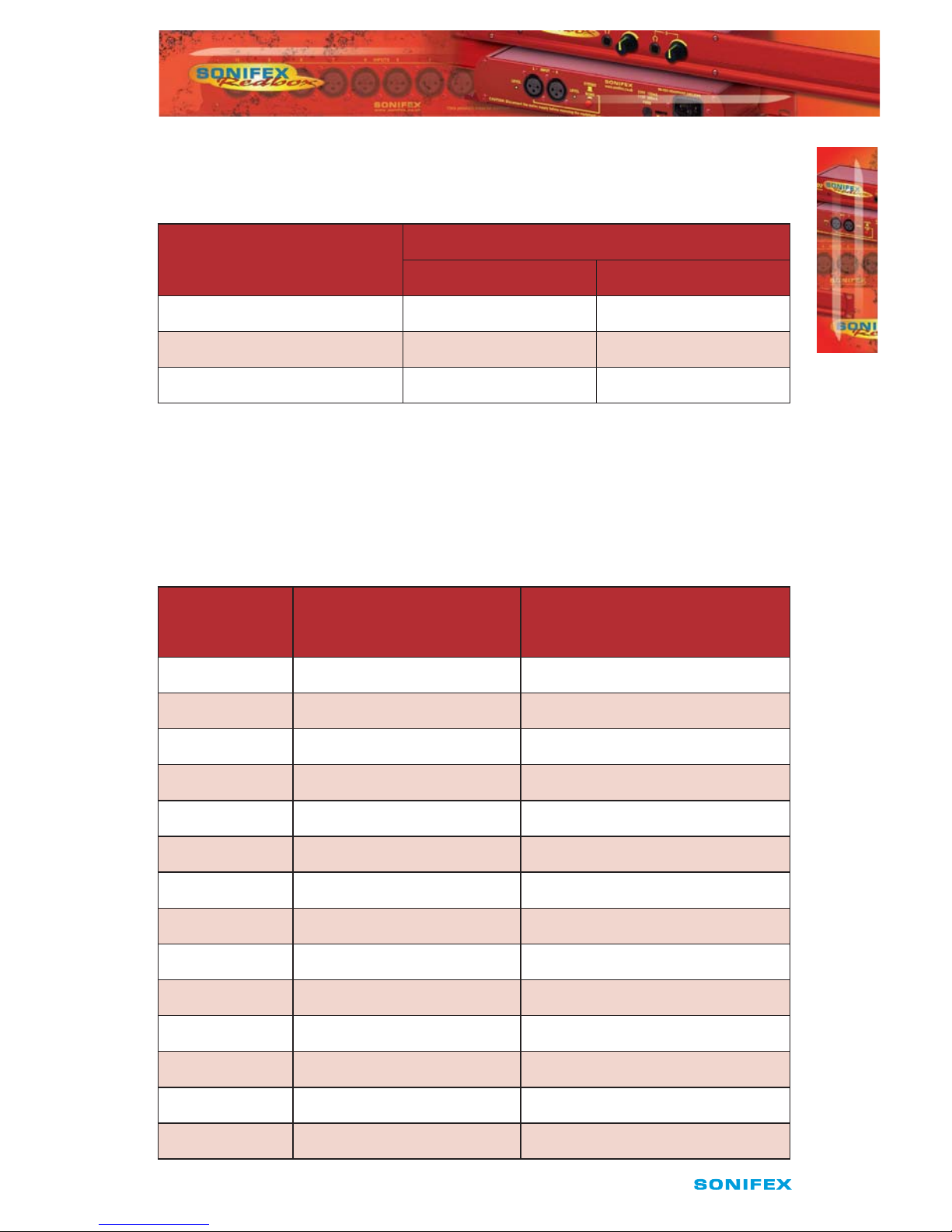
Unpacking the Redbox Embedder/De-embedder
The Redbox Embedder/De-embedder is shipped with the following equipment. Please
check your packaging to ensure that you have all of the items below. If anything is missing,
please contact the supplier of your equipment immediately.
Item Quantity Redbox Embedder/De-embedder
Redbox Embedder/De-embedder 1
IEC Mains lead tted with moulded mains plug 1
Handbook and warranty card 1
Fig A: Packing List
Each Redbox Embedder/De-embedder is shipped in protective packaging and should be
inspected for damage before use. Where an item is found to have transit damage, notify
the carrier immediately with all the relevant details of the shipment. Packing materials
should be kept for inspection and also for if the product needs to be returned.
Returning the Warranty Card
In order to register the date of purchase so that we can keep you informed of any design
improvements or modications, it is important to complete the warranty registration
document that is enclosed and return it to Sonifex Ltd in the UK.
For your own records you should write down the serial number (which can be found on the
rear of the Redbox Embedder/De-embedder.
Serial Number ………………………………………
WARRANTY

iv
Redbox Embedder/De-embedder User Handbook
SAFETY INFORMATION
Safety Information
Safety of Mains Operated Equipment
This equipment has been designed to meet the safety regulations currently
advised in the country of purchase and it conforms to the safety regulations
specied by use of the CE Mark.
Warning : There are no user serviceable parts inside the equipment. If you should ever
need to look inside the unit, always disconnect the mains supply before removing the
equipment covers.
Voltage Setting Checks
Ensure that the machine operating voltage is correct for your mains power supply by
checking the box in which your Redbox was supplied. The voltage is shown on the box
label. This product is continuously rated 85 - 264 VAC, 47 - 63Hz. Please note that all
Redboxes are either switchable between 115V and 230V, or have a universal power supply.
Fuse Rating
The Redbox Embedder/De-embedder is supplied with a single fuse in the live conducting
path of the mains power input. For reasons of safety it is important that the correct rating
and type of fuse is used. Incorrectly rated fuses could present a possible re hazard, under
equipment fault conditions. The fuse rating for the Redbox Embedder/De-embedder is:
Continuously rated 85 - 264 VAC, 47 - 63Hz - 2A, 5 x 20mm SB
The active fuse is tted on the outside rear panel of the unit.
Power Cable and Connection
An IEC power connector is supplied with the Redbox Embedder/De-embedder which has a
moulded plug attached – this is a legal requirement. If no moulded plug has been supplied
with your Redbox Embedder/De-embedder, please contact your supplier, because an IEC
connector is always supplied from the Sonifex factory.
If for any reason, you need to use the Redbox Embedder/De-embedder with a dierent
power cable, you should use the following wiring guidelines.
Wire Colour Connection
Green, or green and yellow Earth (E)
Blue, or Black Neutral (N)
Brown, or Red Live (L)
Fig B: Power Connections
Connect the equipment in accordance with the connection details and before applying
power to the unit, check that the machine has the correct operating voltage for your mains
power supply.
Important Note : The terminal marked on the rear panel must be earthed.
SAFETY INFORMATION
Redbox Embedder/De-embedder User Handbook
v
SAFETY INFORMATION
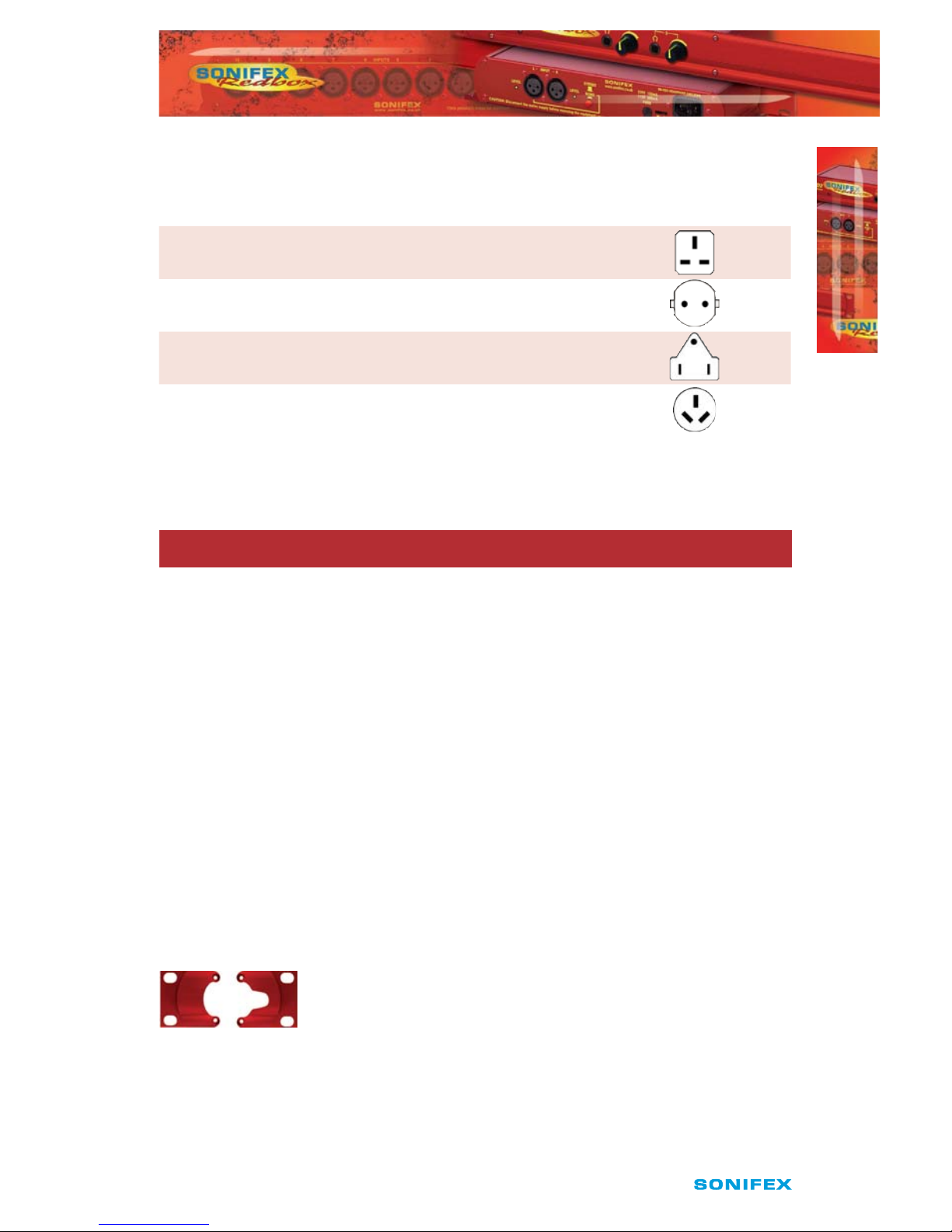
Ordering the Correct Mains Lead
When ordering a Redbox from Sonifex, it is helpful if you can specify your required
operating voltage and mains lead. After the product code add:
UK, for 230V, UK 3 pin to IEC lead
EC, for 230V, European Schuko 2 pin to IEC lead
US, for 115V, 3 pin to IEC lead
AU for 230V, Australasian 3 pin to IEC lead
Fig C: Mains Lead Table
E.g. order Redbox Embedder/De-embedder UK for a UK IEC lead to be supplied.
Installation Information
Atmosphere
The units should be installed in an area that is not subject to excessive temperature
variation (<0°C, >50°C), moisture, dust or vibration.
Electromagnetic Radiation
The cover is connected to earth by means of the xing screws. It is essential to maintain
this earth ground connection to ensure a safe operating environment and provide
electromagnetic shielding.
Fitting Redboxes
Redboxes can be xed to the underside of a mixing desk, or other surfaces using 4.2mm
holes in the sides and xed with 2 x M4 screws or 2 x No. 6 countersink wood screws.
They can also be rack-mounted, with either the front, or rear of the Redbox positioned at
the front of the rack:
Rear Mounting The Redbox Embedder/De-embedder: The RB-RK3 1U rear panel rack kit
can be used for large Redboxes such as the Redbox Embedder/De-embedder.
Fig D: RB-RK3 Large Redbox Rear Rack-mount Kit
Note: When tting the rear-mounting rack-kits, a notch has been left on the inside of
the right-hand rack-piece for the mains cable to pass through. Make sure that the mains
cable has been put through the notch before attaching the right hand rack-piece.
SAFETY INFORMATION

vi
Redbox Embedder/De-embedder User Handbook
SAFETY & INSTALLATION INFORMATION
WEEE & RoHS Directives - Sonifex Statement
The Waste Electrical and Electronic Equipment (WEEE) Directive was agreed on
13 February 2003, along with the related Directive 2002/95/EC on Restrictions
of the use of certain Hazardous Substances in electrical and electronic
equipment (RoHS).
The Waste Electrical and Electronic Equipment Directive (WEEE) aims to minimise the
impacts of electrical and electronic equipment on the environment during their life times
and when they become waste. It applies to a huge spectrum of products. It encourages
and sets criteria for the collection, treatment, recycling and recovery of waste electrical and
electronic equipment. All products manufactured by Sonifex Ltd have the WEEE directive
label placed on the case. It gives a contact for individuals who are unsure about the correct
procedure when the product has reached its “end of use”.
Sonifex Ltd will be happy to give you information about local organisations that can
reprocess the products, or alternatively all products that have reached “end of use” can be
returned to Sonifex and will be reprocessed correctly free of charge.
Sonifex Ltd has phased out the use of certain hazardous substances identied in the
European Union’s Restriction of Hazardous Substances (RoHS) directive. The RoHS
directive limits the use of certain hazardous substances currently used in EEE manufacture,
including lead, mercury, cadmium, hexavalent chromium, and halide-containing
compounds PBB (polybrominated biphenyl) and PBDE (polybrominated diphenyl ether).
Elimination of these substances will result in more environmentally friendly recycling
of electronic equipment. For the products which Sonifex manufacture, the main area
where products were aected was in the use of lead for manufacturing and assembling
electronics circuit boards.
Sonifex Ltd practices lead-free (LF) manufacturing processes. LF solder is used on the
surface-mount PCB manufacturing processes and for hand soldering. The printed circuit
boards (PCBs) used are either gold plated, or immersion tin plated, both of which use no
lead. Historically the PCBs were hot air solder levelled (HASL) PCBs which used tin/lead
based solder.
The manufacturing processes include the assembly of purchased components from
various sources. Product is oered as RoHS compliant, or LF, only after sucient evidence
is received from the component manufacturers that their components are RoHS compliant.
Sonifex Ltd relies solely on the distributor, or manufacturer, of the components for
identication of RoHS compliance. Thus whilst every eort is made to ensure compliance,
Sonifex Ltd makes no warranty, or certication, or declaration of compliance concerning
said components.
Sonifex Ltd denes “Lead Free” as pertaining to any product, which has been manufactured
by Sonifex Ltd using components which have been declared by the manufacturers as
“Lead Free”. All statements by Sonifex Ltd of RoHS compliance are based on component
manufacturer documentation.
SAFETY & INSTALLATION
INFORMATION

Redbox Embedder/De-embedder User Handbook
1
INTRODUCTION
1
INTRODUCTIONINTRODUCTION
1 Redbox Audio Embedders & De-Embedders
The Redbox range of audio embedders and de-embedders use the latest
technology to offer embedding and de-embedding for analogue and digital audio
signals into and out of all 3G, HD and SD-SDI video signals, respectively. There
are currently 4 products in the range.
RB-VHDMA8 3G/HD/SD-SDI De-Embedder, 8 Channel Analogue Outputs
The RB-VHDMA8 is an 8 channel analogue de-embedder contained in a single 19-inch
rack unit. The unit can selectively de-embed up to 8 channels within any audio group of
an SDI video signal, to any of the analogue outputs. After which, the video becomes two
independent paths, where the audio groups can be selectively deleted or passed through
and then sent to the re-clocked SDI outputs.
The de-embedding channel routing is controlled via the front panel buttons and
indicators. There is also LED indication for SDI input status and audio group presence.
The unit can be remote controlled via Ethernet or serial port connections using the Sonifex
SCi software.
It has a triple rate SDI receiver with automatic input rate detection and equalisation along
with two re-clocked and individually buered SDI outputs. It supports the full range of 3G,
HD and SD standards from NTSC and PAL up to 1080p 60Hz.
There is independent level control for each analogue output channel, which can be
adjusted from -24dB through to +24dB in 0.5dB steps.
The analogue outputs have three full-scale gain settings which can be set via jumpers
inside the unit. Allowable settings are +12dBu, +18dBu and +24dBu reference FSD. The
balanced and unbalanced output connections are paralleled, allowing one type to be used
per output.
RB-VHEMA8 3G/HD/SD-SDI Embedder, 8 Channel Analogue Inputs
The RB-VHEMA8 is an 8 channel analogue embedder contained in a single 19-inch rack
unit. The unit can selectively embed up to 8 analogue channels onto either of the two
output video paths which are sent to the re-clocked SDI outputs. It also has the capability
to allow audio groups to be deleted or passed through on each of the two video paths
prior to the embedding process.
The embedding channel routing is controlled via the front panel buttons and indicators.
There is also LED indication for SDI input status and audio group presence.
The unit can be remote controlled via Ethernet or serial port connections using the Sonifex
SCi software.
It has a triple rate SDI receiver with automatic input rate detection and equalisation along
with two re-clocked and individually buered SDI outputs. It supports the full range of 3G,
SD and HD standards from NTSC and PAL up to 1080p 60Hz.

2
Redbox Embedder/De-embedder User Handbook
INTRODUCTION
1
INTRODUCTION
There is independent level control for each analogue input channel, which can be adjusted
from -24dB through to +24dB in 0.5dB steps.
The analogue inputs have three full-scale gain settings which can be set via jumpers
situated inside the unit. Allowable settings are +12dBu, +18dBu and +24dBu for FSD. The
balanced and unbalanced input connections are paralleled, allowing one type to be used
per input.
RB-VHCMA4 3G/HD/SD-SDI Embedder & De-Embedder 4 Channel
Analogue I/O
The RB-VHCMA4 is a 4-channel analogue de-embedder and a 4-channel analogue
embedder combined into a single 19-inch rack unit. The unit can selectively de-embed
up to 4 channels within any audio group of an SDI video signal, to any of the analogue
outputs. After which, the video becomes two independent paths where the audio groups
can be selectively deleted or passed through. The unit then embeds any of the 4 analogue
input channels to available groups within each of the two video paths, which are then sent
to the re-clocked SDI outputs.
The de-embedding and embedding channel routing is controlled via the front panel
buttons and indicators. There is also LED indication for SDI input status and audio group
presence.
The unit can be remote controlled via Ethernet or serial port connections using the Sonifex
SCi software.
It has a triple rate SDI receiver with automatic input rate detection and equalisation along
with two re-clocked and individually buered SDI outputs. It supports the full range of 3G,
SD and HD standards from NTSC and PAL up to 1080p 60Hz.
There is independent level control for each analogue input and output channel, which can
be adjusted from -24dB through to +24dB in 0.5dB steps.
The analogue outputs have three full-scale gain settings which can be set via jumpers
situated inside the unit. Allowable settings are +12dBu, +18dBu and +24dBu reference
FSD Similarly, the analogue inputs full-scale gain settings can be set via jumpers inside
the unit. Allowable settings are +12dBu, +18dBu and +24dBu for FSD. The balanced and
unbalanced connections are paralleled, allowing one type to be used per input or output.
RB-VHCMD16 3G/HD/SD-SDI Embedder & De-Embedder 16 Channel
Digital I/O
The RB-VHCMD16 is a 16-channel de-embedder and 16 channel embedder combined into
a single 19-inch rack unit. The unit can selectively de-embed any channel within any audio
group of an SDI video signal, to any of the digital outputs. After which, the video becomes
two independent paths where the audio groups can be selectively deleted or passed
through. The unit then embeds any of the digital input channels to available groups within
each of the two video paths, which are then sent to the re-clocked SDI outputs.

Redbox Embedder/De-embedder User Handbook
3
INTRODUCTION
1
INTRODUCTION
The de-embedding and embedding channel routing is controlled via the front panel
buttons and indicators. There is also LED indication for SDI input status and audio group
presence.
The unit can be remote controlled via Ethernet or serial port connections using the Sonifex
SCi software.
It has a triple rate SDI receiver with automatic input rate detection and equalisation along
with two re-clocked and individually buered SDI outputs. It supports the full range of 3G,
HD and SD standards from NTSC and PAL up to 1080p 60Hz.
Each digital input is normally sample rate converted to 48kHz before embedding, so that
it is synchronous to the video input. Though sample rate conversion can be bypassed on a
per input basis allowing SMPTE-337M data to be embedded. All digital outputs are output
at 48kHz, synchronous to the video input.
There is independent level control for each digital input and output channel, which can be
adjusted from -24dB through to +24dB in 0.5dB steps.
The digital inputs and outputs are unbalanced AES specication, and can be connected
through either BNC or D-Type connectors. These I/O connections are paralleled, allowing
one type to be used per input or output.
Embedding and De-Embedding Overview
Audio embedding is the process of taking one or more audio signals, formatting them into
packets and then placing them into the ancillary or blanking space of a video signal. Audio
de-embedding is the process of retrieving this audio data from the video signal but not
necessarily removing it. These two processes are standardised by two SMPTE documents,
SMPTE-272M for SD-SDI and SMPTE-299M for HD-SDI and 3G-SDI.
Both of these standards allow for the embedding of 16 channels of 24-bit, 48kHz audio.
Which are divided down into 4 groups of 4 channels.
Each standard consists of a control packet and an audio data packet. The control packets
hold certain control information about the audio to aid in the de-embedding process or
any other receiving equipment. There is one control packet per group, these packets are
optional for SD. The control packet is normally placed in the horizontal blanking period
once per eld or frame. The audio data packets contain the actual audio sample data.
There are considerable dierences between SD and HD, the main ones being that SD data
packets contain only 20-bit data and are of variable length while the HD data packets
contain 24-bit data and are of xed length. The HD packets also provide an error correction
and detection method. The SD standard consists of a further packet, the extended data
packet. These packets contain the 4 least signicant bits of the audio samples to provide
full 24-bit audio.

4
Redbox Embedder/De-embedder User Handbook
RBVHDMA8
RBVHDMA8
2
2 RB-VHDMA8 3G/HD/SD-SDI De-Embedder, 8 Channel
Analogue Outputs
The RB-VHDMA8 is an 8 channel analogue de-embedder contained in a single 19-inch
rack unit. The unit can selectively de-embed up to 8 channels within any audio group of
an SDI video signal, to any of the analogue outputs. After which, the video becomes two
independent paths, where the audio groups can be selectively deleted or passed through
and then sent to the re-clocked SDI outputs.
The de-embedding channel routing is controlled via the front panel buttons and
indicators. There is also LED indication for SDI input status and audio group presence.
The unit can be remote controlled via Ethernet or serial port connections using the Sonifex
SCi software.
It has a triple rate SDI receiver with automatic input rate detection and equalisation along
with two re-clocked and individually buered SDI outputs. It supports the full range of 3G,
HD and SD standards from NTSC and PAL up to 1080p 60Hz.
There is independent level control for each analogue output channel, which can be
adjusted from -24dB through to +24dB in 0.5dB steps.
The analogue outputs have three full-scale gain settings which can be set via jumpers
inside the unit. Allowable settings are +12dBu, +18dBu and +24dBu reference FSD. The
balanced and unbalanced output connections are paralleled, allowing one type to be used
per output.
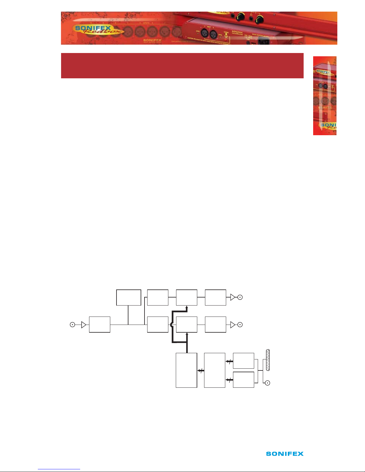
System Block Diagram
Fig 2-1: RB-VHDMA8 System Block Diagram
Analogue
Outputs
Balanced
Unbalanced
Bank 1
DACs
Bank 2
DACs
Channel
Routing
8 Channel
Level
Control
SDI
Input
SDI
Output 2
SDI
Receiver
Audio
De-embedder
SDI
Transmitter
Audio
Pass /
Delete
EQ CD
Audio
Group
Detect
SDI
Transmitter
Audio
Pass /
Delete
SDI
Output 1
CD
4
4
8

Redbox Embedder/De-embedder User Handbook
5
RBVHDMA8
2
RBVHDMA8
Front Panel Indicators & Controls
Fig 2-2: RB-VHDMA8 Front Panel
Power LED
The POWER LED illuminates whilst internal power is present within the unit. If this indicator
is not on, the most likely reason is simply the absence of mains power, but under fault
conditions it may also indicate a ruptured mains fuse or a problem with the internal power
supply module.
Reset Button
In the unlikely event that the unit fails to respond, press the reset button to reboot the unit.
Bank
The BANK button and its indicators are used to select the audio output bank when
controlling the de-embedding channel routing. The button LED is used show whether the
bank is enabled. To enable or disable the bank, press and hold the BANK button for two
seconds until the bank number indicator blinks. When lit green it is enabled and when lit
red it is disabled. When the bank is disabled, all audio outputs are muted.
Bank Channel
The BANK CHANNEL button and its indicators are only used when the unit is operating in
Channel mode and are used to select the audio output bank channel when controlling the
de-embedding channel routing. The button LED is used to show whether the channel is
enabled. To enable or disable the channel, press and hold the BANK CHANNEL button for
two seconds until the channel number indicator blinks. When lit green it is enabled and
when it is lit red it is disabled. When the channel is disabled, the audio output is muted.
The channel will also be muted if the bank is disabled, even if the channel is enabled.
Group
The GROUP button and its indicators are used to select the group audio number within the
video signal to de-embed and send to analogue outputs in the currently selected bank.
Group Channel
The GROUP CHANNEL button and its indicators are used to select the channel number
within the currently selected group to de-embed and send to the analogue output in the
currently selected bank and bank channel. This button is only used when operating in
Channel mode.
Power
LED
BANK
Button
BANK
Channel
GROUP
Button
GROUP
Channel
STATUS
Button

6
Redbox Embedder/De-embedder User Handbook
RBVHDMA8
RBVHDMA8
2
Status
This button is used to used to enter and exit the group deletion mode, which is discussed
later.
Audio Group Detection
The four audio group indicators associated with the STATUS button, display the audio
groups which are present in the SDI video signal. If an audio group is present, its relevant
indicator will be lit. This is useful to determine which groups are available for deembedding and/or deleting.
Lock Indicator
The lock indicator is lit when the the SDI receiver has detected and locked to the incoming
video format. If the input is disconnected or is intermittent then the lock indicator will stay
unlit.
Output Indicators
These two indicators are used to indicate which one of the two outputs are selected when
conguring audio packets for deletion.
Rear Panel Connections
Fig 2-3: RB-VHDMA8 Rear Panel
Mains Power
Power is applied via a standard three-pin IEC male socket. Mains voltages between 85V
and264V AC and frequencies between 47 and 63Hz are accepted without adjustment. A
2A, 5 x 20mm SB fuse is used. The Earth pin MUST be connected to ensure safety.
Remote Control
The unit can be controlled remotely either by serial RS-232 or Ethernet using the Sonifex
SCi software. Using remote control allows the user to monitor the status of the unit and
also set various options and settings not available via the front panel.
PowerRS232
Ethernet Fuse
De-embed Bank
Bal Outputs
Bank 1
Unbal
Outputs
Bank 2
Unbal
Outputs
SDIINSDI Outputs
1 and 2

Redbox Embedder/De-embedder User Handbook
7
RBVHDMA8
RBVHDMA8
2
RS232 Remote Control
A 9-way female D-type connector carries a standard RS232 interface via which advanced
conguration options may be set and many functions may be remotely controlled. The pin
assignations are as follows:
Pin No. Function
1 Unused
6 Unused
2 Data transmit (TX)
7 Unused
3 Data receive (RX)
8 Unused
4 Unused
9 Unused
5 Ground
The RB-VHDMA8 will interface directly with personal computer serial ports at standard
RS232 signal levels using a straight-through cable. The default format is 19200 baud with 8
data bits, even parity and 1 stop bit. Sonifex SCi software, when installed on a suitable PC,
provides straightforward graphical access to all remote control and conguration options
via both RS232 and Ethernet interfaces. Alternatively, commands may be issued from any
text-based terminal program (e.g. Hyperterminal) or custom software may be developed
for specic requirements.
Ethernet
The Ethernet port is connected using a standard RJ-45 connector on the rear of the panel.
It is a 10/100Mbps link. The unit is shipped with DHCP enabled to allow the unit to be
plug and play if the users local area network has a DHCP server. If one is not available on
the network and the unit cannot retrieve a valid IP address after 45 seconds it will default
to a static address. This static address is set to 192.168.0.100 by default but can be altered
through SCi using the serial port connection. If DHCP is not required then this can also be
disabled through SCi using the serial port connection.

8
Redbox Embedder/De-embedder User Handbook
RBVHDMA8
2
RBVHDMA8
The Network connectors pin assignations are as follows:
Network Connector (RJ-45)
Pin No. Function
1 Transmit Data (Positive)
2 Transmit Data (Negative)
3 Receive Data (Positive)
4 No connection
5 No connection
6 Receive Data (Negative)
7 No connection
8 No connection
SDI Input
The SDI input is connected using a single female BNC and has a 75Ω input impedance. It is
a triple rate SDI receiver with automatic input rate detection and equalisation. It supports
the full range of 3G, SD and HD standards from NTSC and PAL up to 1080p 60Hz. The status
of the input is displayed on the status LEDs on the front panel. When the SDI input rate
and format has been detected, the SDI lock indicator will be lit.
SDI Outputs
The two SDI outputs are connected using the two female BNC connectors on the rear
panel. They have a 75 Ω output impedance in accordance with the SMPTE standard
and are both re-clocked and independently buered. Each output can be congured
separately for group deletion settings.
Audio Connections
Analogue Audio Outputs
The RB-VHDMA8 has eight analogue outputs which are separated into two banks of
four channels. These can be connected using balanced connections through the D-type
connectors or unbalanced connections through BNC connectors, all are available on the
rear panel. The balanced analogue outputs can be wired unbalanced by connecting nonphase (-) pin to the ground pin for that output, and then connecting the audio signal to the
phase (+) pin.
The two output types are connected internally, so please ensure that only one type of
connection is used per output.
Redbox Embedder/De-embedder User Handbook
9
RBVHDMA8
2
RBVHDMA8
Full Scale Setting
The analogue output full-scale settings, which determine the full-scale 0dBFS level for the
digital audio, are set internally via jumpers. They are factory set to +18dBu by default.
Full-scale Settings Jumper
JP1 JP2
+12dBu Not tted Not tted
+18dBu Fitted Not tted
+24dBu Fitted Fitted
Audio Output Gain Adjustment
The default audio output gain is unity. However, to accommodate lower or higher level
sources it is possible to introduce gain or attenuation on a per channel basis. Each audio
channel has an adjustable gain range from -24dBu to +24dBu in 0.5dB increments. This is
set using the remote Control ports. Once set, this value is stored and reloaded each time
the unit is powered on.
RB-VHDMA8 D-type Pin-out
Pin No. Function
De-Embed Bank 1
Function
De-Embed Bank 2
1 Channel 1+ Channel 1+
14 Channel 1- Channel 1-
2 Channel 1 Ground Channel 1 Ground
15 Channel 2+ Channel 2+
3 Channel 2- Channel 2-
16 Channel 2 Ground Channel 2 Ground
4 Channel 3+ Channel 3+
17 Channel 3- Channel 3-
5 Channel 3 Ground Channel 3 Ground
18 Channel 4+ Channel 4+
6 Channel 4- Channel 4-
19 Channel 4 Ground Channel 4 Ground
7 to 13 Do not connect Do not connect
20 to 25 Do not connect Do not connect

10
Redbox Embedder/De-embedder User Handbook
2
RBVHDMA8
RBVHDMA8
Control Modes
There are two modes available to control the de-embedding channel routing process.
These are the BANK mode and the CHANNEL mode.
Bank Mode
In Bank mode, audio is routed on a per bank basis, so when controlling de-embedding a
group of audio is selected to be sent to a bank.
Channel Mode
In Channel mode, audio is routed on a per channel basis, this allows for maximum exibility
when de-embedding, allowing any channel within any group be sent to any channel of any
of the available audio output banks.
Changing Control Mode
To switch between Bank and Channel control modes, simultaneously press and hold
the GROUP CHANNEL and BANK CHANNEL buttons for 5 seconds. The mode will switch
after this time and the button can be released. Bank mode is in use when both the BANK
CHANNEL and GROUP CHANNEL button LEDs are not lit. Conversely, when Channel mode
is in use these two LEDs are lit.
When switching from Channel to Bank mode, all channel mappings are reset to default.
When switching from Bank to Channel mode, the channel mappings are retained to allow
for further modication.
De-Embedding
The unit is always de-embedding, automatically reading all the audio data contained in the
video signal as it appears to the de-embedding block. Using the front panel controls the
user can control which of these channels or groups within the video input are routed to the
analogue outputs.
If an SD video signal is being received and extended audio data is detected, then the unit
will automatically use this to reproduce full 24-bit audio data and no user intervention is
required.
Bank Mode
In bank mode, de-embedding is controlled on a per group basis. So whole groups are
selected to be output on a particular bank.
1 To de-embed a group of audio to a specic bank.
2 Select the output bank number, using the BANK button.
3 Select the group to de-embed using the GROUP button.
The BANK button LED will show whether the bank is enabled. To enable de-embedding to
this bank, press and hold the BANK button for two seconds, until the button turns green.
This indicates that de-embedding is enabled to this bank. To turn o de-embedding, then
hold the BANK button down until the button turns red. The bank number indicator will
blink to show that the change has been applied.

Redbox Embedder/De-embedder User Handbook
11
2
RBVHDMA8
RBVHDMA8
In this mode, the channels of the group are mapped directly to the bank channels. For
example channel 1 in the selected group is de-embedded to channel 1 of the selected
bank. Channel 2 in the selected group is de-embedded to channel 2 of the selected
bank etc.
Cycling through the banks using the BANK button, allows the user to determine which
banks are currently enabled for de-embedding and will also show the source group for that
bank.
Channel Mode
In channel mode, de-embedding is controlled on a per channel basis. So individual
channels within a group are selected to be output on a particular channel within a bank.
To de-embed a group channel of audio to a specic bank channel.
1 Select the output bank number using the BANK button.
2 Select the output bank channel using the BANK CHANNEL button.
3 Select the group to de-embed using the GROUP button.
4 Select the group channel to de-embed using the GROUP CHANNEL button.
To enable de-embedding to this channel, both the BANK and BANK CHANNEL must be
enabled. This is indicated by the button LED being lit green. If either are red, then simply
enable them by holding down the relevant button for two seconds.
Cycling through the banks and bank channels using the BANK and BANK CHANNEL buttons
respectively, allows the user to determine which bank channels are currently enabled for
de-embedding and will also show the source for that bank channel.
Deleting Audio Groups
If the SDI video signal contains audio groups which require deleting, then these can be
deleted on a per output basis. For example if the video input contained all four audio
groups then it is possible to delete all groups on output 1 and only groups 1 and 2 on
output 2.
The unit will also delete any ancillary packets marked for deletion and realign the packets
to make maximum use of the available ancillary space.
To delete audio groups the unit is put into a special group deletion mode. To enter this
mode press and hold the STATUS button for 5 seconds. The front panel button indicators
will change so that only the GROUP, GROUP CHANNEL and STATUS buttons are available.
The GROUP button and indicators are used to select the group number, the GROUP
CHANNEL button is used to enable or disable deletion on this group and the STATUS
button is used to select the output. Once the desired settings have been set, then using
the same method to enter the group deletion mode will exit it. The new settings will be
applied as soon as the unit returns to its normal operating mode.

12
Redbox Embedder/De-embedder User Handbook
2
RBVHDMA8
RBVHDMA8
Technical Specication For RB-VHDMA8
Front Panel Controls & Indicators
De-embed Bank Select: Bank 1 or 2
Bank Channel Select: Channels 1, 2, 3 or 4
Group Select: Groups 1, 2, 3 or 4
Group Channel Select: Group channels 1,2,3 or 4
Status: 1 x SDI input status LED
2 x SDI output LEDs
4 x Audio group status LEDs
Audio Specications
Max. Output Level: +24dBu (balanced)
Output Impedance: <50Ω (balanced)
Full Scale Settings: 12dBu, 18dBu or 24dBu ref FSD (jumper selectable)
Signal to Noise: Better than -106dB (RMS A-weighted at 24-bit, balanced)
Distortion and Noise: Better than -85dB THD+N at 1kHz (balanced)
De-embed Delay: 3G/HD/SD: 1.1 ms
Connections
Analogue Audio Outputs: 8 output channels via BNC (unbalanced) or D-type
socket (balanced)
Analogue Audio Connectors: 8 x BNC
2 x 25-way D-type
Power Supply: Universal ltered IEC, continuously rated 85-264VAC
@47-63Hz, fused, max 14W
Equipment Type
RB-VHDMA8 3G/HD/SD-SDI De-embedder, 8 channel analogue outputs

Redbox Embedder/De-embedder User Handbook
13
2
RBVHDMA8
RBVHDMA8
Remote Interface Commands & Responses Protocol
Sonifex SCi remote control software handles all communication with the unit via a
convenient graphical user interface. However, this protocol is provided for those users who
wish to develop their own remote control applications or communicate with the unit using
a text-based terminal program.
Command Format
Commands are case-insensitive and should be terminated in a carriage return character, a
line feed character may be sent but it will be ignored. Further commands sent before the
rst command is acknowledged will be ignored. Responses will be CR & LF terminated.
Remote Control Commands
Command Description Response
COM:b,d,p,s Serial Port Settings
b is the baud rate (9600, 19200,
38400, 57600 and 115200)
d is the data bits (7 or 8)
p is the parity (N, O, E)
s is the stop bits (1 or 2)
ACK:
CTM:m Control Mode
m is the mode
0 = bank
1 = channel
ACK:
DEL:o,g,e Delete Audio Group
o is the output (0 or 1)
g is the group (0 to 3)
e is the option
0 = don’t delete
1 = delete
ACK:
DWN: Initiates a Firmware Update
DMC:b,c,e De-Embed Bank Channel Enable
This is only used when operating in
advanced mode
b is the bank (0 to 3)
c is the channel (0 to 3)
e is the option
0 = o
1 = on
ACK:

14
Redbox Embedder/De-embedder User Handbook
RBVHDMA8
2
RBVHDMA8
Command Description Response
DMB:b,e De-Embed Bank Enable
b is the group (0 to 3)
e is the option
0 = o
1 = on
ACK:
DMR:b[,bc],g[,gc] De-Embed Route Control
b is the bank (0 to 3)
bc is the bank channel (0 to 3) – only
in channel mode
g is the group (0 to 3)
gc is the group channel (0 to 3) –
only in channel mode
ACK:
FPL:e Front Panel Lock
e is the enable option
0 = o
1 = on
ACK:
MAC: MAC Address
Returns the MAC address of the unit
in 12 hex characters.
MAC:XXXXXXXXXXXX
NET:x.x.x.x,y.y.y.y,z.z.z.z Network Address Settings
x.x.x.x is a valid IP address
y.y.y.y is a valid subnet mask
z.z.z.z is a valid gateway address
ACK:
NOP:o,v Network Options
o is the option number
0 = DHCP
v is the option value
0 = o
1 = on
ACK:
OPG:b,c,g Output Gain
b is the bank number (0 or 1)
c is the channel (0-3)
g is the gain value 0 to 96
0 = -24dBu and 96 = +24dBu
ACK:
SRQ: Status Request
UID: Unit ID UID:RB-VHEMA8
VER: Version information
M1.m1.b1 is the Firmware version
M2.m2.b2 is the FPGA version
VER:M1.m1.b1, M2.m2.b2
Redbox Embedder/De-embedder User Handbook
15
RBVHEMA8
3
RBVHEMA8
3 RB-VHEMA8 3G/HD/SD-SDI Embedder, 8 Channel
Analogue Inputs
The RB-VHEMA8 is an 8 channel analogue embedder contained in a single 19-inch rack
unit. The unit can selectively embed up to 8 analogue channels onto either of the two
output video paths which are sent to the re-clocked SDI outputs. It also has the capability
to allow audio groups to be deleted or passed through on each of the two video paths
prior to the embedding process.
The embedding channel routing is controlled via the front panel buttons and indicators.
There is also LED indication for SDI input status and audio group presence.
The unit can be remote controlled via Ethernet or serial port connections using the Sonifex
SCi software.
It has a triple rate SDI receiver with automatic input rate detection and equalisation along
with two re-clocked and individually buered SDI outputs. It supports the full range of 3G,
SD and HD standards from NTSC and PAL up to 1080p 60Hz.
There is independent level control for each analogue input channel, which can be adjusted
from -24dB through to +24dB in 0.5dB steps.
The analogue inputs have three full-scale gain settings which can be set via jumpers
situated inside the unit. Allowable settings are +12dBu, +18dBu and +24dBu for FSD. The
balanced and unbalanced input connections are paralleled, allowing one type to be used
per input.
System Block Diagram
Fig 3-1: RB-VHEMA8 Block Diagram
SDI
Input
SDI
Output 2
SDI
Receiver
Audio
Embedder
SDI
Transmitter
Audio
Pass /
Delete
EQ CD
Audio
Group
Detect
Audio
Embedder
SDI
Transmitter
Audio
Pass /
Delete
SDI
Output 1
CD
8 Channel
Level
Control
Bank 1
ADCs
Bank 2
ADCs
Channel
Routing
Analogue
Inputs
Balanced
Unbalanced
8
4
4

16
Redbox Embedder/De-embedder User Handbook
RBVHEMA8
3
RBVHEMA8
Front Panel Indicators & Controls
Fig 3-2: RB-VHEMA8 Front Panel
Power LED
The POWER LED illuminates whilst internal power is present within the unit. If this indicator
is not on, the most likely reason is simply the absence of mains power, but under fault
conditions it may also indicate a ruptured mains fuse or a problem with the internal power
supply module.
Reset Button
In the unlikely event that the unit fails to respond, press the reset button to reboot the unit.
Bank
The BANK button and its indicators are used to select the audio input bank when
controlling the embedding channel routing.
Bank Channel
The BANK CHANNEL button and its indicators are only used when the unit is operating in
Channel mode and are used to select the audio input bank channel when controlling the
embedding channel routing.
Group
The GROUP button and its indicators are used to select the group number with which to
embed the analogue input channels to. The button LED is used show whether embedding
is enabled to the currently selected group. To enable or disable the embedding to a group,
press and hold the GROUP button for two seconds until the group number indicator blinks.
When lit green it is enabled and when it is lit red it is disabled. When the group is disabled,
no embedding is done to that group number.
Group Channel
The GROUP CHANNEL and its indicators are used to select the channel within the currently
selected group with which to embed the analogue input channel to. This button is only
used when operating in Channel mode. The button LED is used show whether the channel
is enabled for embedding. To enable or disable the channel, press and hold the GROUP
CHANNEL button for two seconds until the channel number indicator blinks. When lit
green it is enabled and when it is lit red it is disabled. When the channel is disabled, no
audio is embedded to that channel. The channel will also not be embedded if the group is
not enabled for embedding, even if the channel is enabled.
Status
This button is used to select the output number when controlling the embedding routing.
It is also used to enter and exit the group deletion mode.
Power
LED
BANK
Button
BANK
Channel
GROUP
Button
GROUP
Channel
STATUS
Button

Redbox Embedder/De-embedder User Handbook
17
3
RBVHEMA8
RBVHEMA8
Audio Group Detection
The four audio group indicators associated with the STATUS button display the audio
groups present in the SDI input. If an audio group is present, its relevant indicator will be
lit. This is useful to determine which groups require deleting or which groups are available
for embedding.
Lock Indicator
The lock indicator is lit when the the SDI receiver has detected and locked to the incoming
video format. If the input is disconnected or is intermittent then the lock indicator will stay
unlit.
Output Indicators
These two indicators are used to indicate which one of the two outputs are selected when
conguring the embedding routing or when conguring audio packets for deletion.
Rear Panel Connections
Fig 3-3: RB-VHEMA8 Rear Panel
Mains Power
Power is applied via a standard three-pin IEC male socket. Mains voltages between 85V
and264V AC and frequencies between 47 and 63Hz are accepted without adjustment. A
2A, 5 x 20mm SB fuse is used. The Earth pin MUST be connected to ensure safety.
Remote Control
The unit can be controlled remotely either by serial RS-232 or Ethernet using the Sonifex
SCi software. Using remote control allows the user to monitor the status of the unit and
also set various options and settings not available via the front panel.
RS232 Remote Control
A 9-way female D-type connector carries a standard RS232 interface via which advanced
conguration options may be set and many functions may be remotely controlled. The pin
assignations are as follows:
Pin No. Function
1 Unused
6 Unused
2 Data transmit (TX)
7 Unused
PowerRS232
Ethernet Fuse
Embed Bank Bal
Inputs
Bank 1
Unbal Inputs
Bank 2
Unbal Inputs
SDI
IN
SDI Outputs
1 and 2

18
Redbox Embedder/De-embedder User Handbook
RBVHEMA8
RBVHEMA8
3
3 Data receive (RX)
8 Unused
4 Unused
9 Unused
5 Ground
The RB-VHEMA8 will interface directly with personal computer serial ports at standard
RS232 signal levels using a straight-through cable. The default format is 19200 baud with 8
data bits, even parity and 1 stop bit. Sonifex SCi software, when installed on a suitable PC,
provides straightforward graphical access to all remote control and conguration options
via both RS232 and Ethernet interfaces. Alternatively, commands may be issued from any
text-based terminal program (e.g. Hyperterminal) or custom software may be developed
for specic requirements.
Ethernet
The Ethernet port is connected using a standard RJ-45 connector on the rear of the panel.
It is a 10/100Mbps link. The unit is shipped with DHCP enabled to allow the unit to be
plug and play if the users local area network has a DHCP server. If one is not available on
the network and the unit cannot retrieve a valid IP address after 45 seconds it will default
to a static address. This static address is set to 192.168.0.100 by default but can be altered
through SCi using the serial port connection. If DHCP is not required then this can also be
disabled through SCi using the serial port connection.
The Network connectors pin assignations are as follows:
Network Connector (RJ-45)
Pin No. Function
1 Transmit Data (Positive)
2 Transmit Data (Negative)
3 Receive Data (Positive)
4 No connection
5 No connection
6 Receive Data (Negative)
7 No connection
8 No connection

Redbox Embedder/De-embedder User Handbook
19
3
RBVHEMA8
RBVHEMA8
SDI Input
The SDI input is connected using a single female BNC and has a 75Ω input impedance. It is
a triple rate SDI receiver with automatic input rate detection and equalisation. It supports
the full range of 3G, SD and HD standards from NTSC and PAL up to 1080p 60Hz. The status
of the input is displayed on the status LEDs on the front panel. When the SDI input rate
and format has been detected, the SDI lock indicator will be lit.
SDI Outputs
The two SDI outputs are connected using the two female BNC connectors on the rear
panel. They have a 75Ω output impedance in accordance with the SMPTE standard and are
both re-clocked and independently buered. Each output can be congured separately for
embedding and group deletion settings.
Audio Connections
Analogue Audio Inputs
The RB-VHEMA8 has eight analogue input channels which are separated into two
banks of four channels. The analogue audio inputs are converted to digital audio using
high performance, low noise stereo 24-bit ADCs. They are connected using balanced
connections through the D-type connectors or unbalanced connections through BNC
connectors, all are available on the rear panel. The balanced analogue inputs can be wired
unbalanced by connecting non-phase (-) pin to the ground pin for that input, and then
connecting the audio signal to the phase (+) pin.
The two input types are connected internally, so ensure that only one type of connection is
used per input.
Full Scale Setting
The analogue input full-scale settings, which determine the full-scale 0dBFS level for the
digital audio, are set internally via jumpers. They are factory set to +18dBu by default.
Full-scale Settings Jumper
JP1 JP2
+12dBu Not tted Not tted
+18dBu Fitted Not tted
+24dBu Not tted Fitted
Audio Input Gain Adjustment
The default audio input gain is unity. However, to accommodate lower or higher level
sources it is possible to introduce gain or attenuation on a per channel basis. Each audio
input has an adjustable gain range from -24dBu to +24dBu in 0.5dB increments. This is set
using the remote Control ports. Once set, this value is stored and reloaded each time the
unit is powered on.

20
Redbox Embedder/De-embedder User Handbook
RBVHEMA8
RBVHEMA8
3
RB-VHEMA8 D-type Pin-out
Pin No. Function
Embed Bank 1
Function
Embed Bank 2
1 Channel 1+ Channel 1+
14 Channel 1- Channel 1-
2 Channel 1 Ground Channel 1 Ground
15 Channel 2+ Channel 2+
3 Channel 2- Channel 2-
16 Channel 2 Ground Channel 2 Ground
4 Channel 3+ Channel 3+
17 Channel 3- Channel 3-
5 Channel 3 Ground Channel 3 Ground
18 Channel 4+ Channel 4+
6 Channel 4- Channel 4-
19 Channel 4 Ground Channel 4 Ground
7 to 13 Do not connect Do not connect
20 to 25 Do not connect Do not connect
Control Modes
There are two modes available to control the embedding channel routing process. These
are the BANK mode and the CHANNEL mode.
Bank Mode
In Bank mode, audio is routed on a per bank basis, so when controlling embedding, a bank
of audio is selected to be embedded into a group.
Channel Mode
In Channel mode, audio is routed on a per channel basis. This allows for maximum
exibility when embedding, allowing any audio input channel to be embedded to any
channel within any group.
Changing Control Mode
To switch between Bank and Channel control modes, simultaneously press and hold
the GROUP CHANNEL and BANK CHANNEL buttons for 5 seconds. The mode will switch

Redbox Embedder/De-embedder User Handbook
21
3
RBVHEMA8
RBVHEMA8
after this time and the button can be released. Bank mode is in use when both the BANK
CHANNEL and GROUP CHANNEL button LEDs are not lit. Conversely, when Channel mode
is in use these two LEDs are lit.
When switching from Channel to Bank mode, all channel mappings are reset and no
groups are selected for embedding. When switching from Bank to Channel mode, the
channel mappings are retained to allow for further modication.
Embedding
The analogue audio inputs can be embedded into any of the four available groups in the
two SDI outputs. They can be embedded on a per bank basis in the Bank control mode, or
a per channel basis in the Channel control mode. If you embed to a group which is already
present in the SDI video input, then this group is automatically deleted from the video
input prior to the embedding block.
Bank Mode
To embed a bank of audio to a specic group.
1 Select the SDI Output, using the STATUS button.
2 Select the bank of audio, using the BANK button.
3 Select the group to embed to, using the GROUP button.
The GROUP button LED will indicate whether embedding is enabled to this group. To
enable embedding to this group, press and hold the GROUP button for two seconds, until
the button turns green. The group number LED will blink to indicate that the change
has been applied. This indicates that embedding is enabled to this group. To disable
embedding to this group, then hold the GROUP button down until the button turns red.
In this mode, the channels of the bank are mapped directly to the group channels. For
example channel 1 in the selected bank is embedded to channel 1 of the selected group.
Channel 2 in the selected bank is embedded to channel 2 of the selected group etc.
Cycling through the groups using the GROUP button, allows the user to determine which
groups are currently enabled for embedding and will also show the source for that group.
Channel Mode
To embed a channel of audio to a specic channel within a group.
1 Select the SDI Output, using the STATUS button.
2 Select the bank of audio, using the BANK button.
3 Select the bank channel using the the BANK CHANNEL button.
4 Select the group to embed to using the GROUP button.
5 Select the group channel to embed to using the GROUP CHANNEL button.

22
Redbox Embedder/De-embedder User Handbook
RBVHEMA8
RBVHEMA8
3
To enable embedding to this group and channel, both the GROUP and GROUP CHANNEL
must be enabled. This is indicated by the button LED being lit green. If either are red, then
simply enable them by holding down the relevant button for two seconds. Embedding will
only take place if the GROUP is enabled. If the GROUP CHANNEL is enabled and the GROUP
is not, then no embedding will occur.
Cycling through the groups and group channels using the GROUP and GROUP CHANNEL
buttons respectively, allows the user to determine which groups are currently enabled for
embedding and their sources.
SD & 24-bit Audio
The Redbox embedders provide full support for 24-bit audio embedding in SD by making
use of the extended data packets as per SMPTE-272M. By default the unit embeds 20-bit
audio. To enable the full 24-bit embedding, this must be set through the remote control
port.
Before enabling this option, ensure that any receiving equipment is capable of handling
the extended data packets.
Deleting Audio Groups
If the SDI video signal contains audio groups which require deleting, then these can be
deleted on a per output basis. For example if the video input contained all four audio
groups then it is possible to delete all groups on output 1 and only groups 1 and 2 on
output 2.
The unit will also delete any ancillary packets marked for deletion and realign the packets
to make maximum use of the available ancillary space.
To delete audio groups the unit is put into a special group deletion mode. To enter this
mode press and hold the STATUS button for 5 seconds. The front panel button indicators
will change so that only the GROUP, GROUP CHANNEL and STATUS buttons are available.
The GROUP button and indicators are used to select the group number, the GROUP
CHANNEL button is used to enable or disable deletion on this group and the STATUS
button is used to select the output. Once the desired settings have been set, then using
the same method to enter the group deletion mode will exit it. The new settings will be
applied as soon as the unit returns to its normal operating mode.

Redbox Embedder/De-embedder User Handbook
23
3
RBVHEMA8
RBVHEMA8
Technical Specication For RB-VHEMA8
Front Panel Controls & Indicators
Embed Bank Select: Bank 1 or 2
Bank Channel Select: Channels 1, 2, 3 or 4
Group Select: Groups 1, 2, 3 or 4
Group Channel Select: Group channels 1,2,3 or 4
Status: 1 x SDI input status LED
2 x SDI output LEDs
4 x Audio group status LEDs
Audio Specications
Maximum Input Level: +27dBu (balanced)
Input Impedance: >10kΩ bridging (balanced)
Input Levels: +12dBu, +18dBu or +24dBu for FSD (jumper selectable)
Signal to Noise: Better than -113dBFS (RMS A-weighted at 24-bit, balanced)
Distortion and Noise: Better than -100dB THD+N at 1kHz (balanced)
Embed Delay: SD: 600 us
3G/HD: 300 us
Connections
Analogue Audio Inputs: 8 input channels via BNC (unbalanced) or D-type
socket (balanced)
Analogue Audio Connectors: 8 x BNC
2 x 25-way D-type
Power Supply: Universal ltered IEC, continuously rated 85-264VAC
@47-63Hz, fused, max 18W
Equipment Type
RB-VHEMA8 3G/HD/SD-SDI embedder, 8 channel analogue inputs

24
Redbox Embedder/De-embedder User Handbook
RBVHEMA8
3
RBVHEMA8
Remote Interface Commands & Responses Protocol
Sonifex SCi remote control software handles all communication with the unit via a
convenient graphical user interface. However, this protocol is provided for those users who
wish to develop their own remote control applications or communicate with the unit using
a text-based terminal program.
Command Format
Commands are case-insensitive and should be terminated in a carriage return character, a
line feed character may be sent but it will be ignored. Further commands sent before the
rst command is acknowledged will be ignored. Responses will be CR & LF terminated.
Remote Control Commands
Command Description Response
COM:b,d,p,s Serial Port Settings
b is the baud rate (9600, 19200, 38400,
57600 and 115200)
d is the data bits (7 or 8)
p is the parity (N, O, E)
s is the stop bits (1 or 2)
ACK:
CTM:m Control Mode
m is the mode
0 = bank
1 = channel
ACK:
DEL:o,g,e Delete Audio Group
o is the output (0 or 1)
g is the group (0 to 3)
e is the option
0 = don’t delete
1 = delete
ACK:
DWN: Initiates a Firmware Update
EMC:o,g,c,e Embed Group Channel Enable
This is only used when operating in
channel mode
o is the output (0 or 1)
g is the group (0 to 3)
c is the channel (0 to 3)
e is the option
0 = o
1 = on
ACK:

Redbox Embedder/De-embedder User Handbook
25
RBVHEMA8
3
RBVHEMA8
Command Description Response
EMG:o,g,e Embed Group Enable
o is the output (0 or 1)
g is the group (0 to 3)
e is the option
0 = o
1 = on
ACK:
EMR:o,g[,gc],b[,bc] Embed Route Control
o is the output (0 or 1)
g is the group (0 to 3)
gc is the group channel (0 to 3) – only in
channel mode
b is the bank (0 or 1)
bc is the bank (0 to 3) – only in channel
mode
ACK:
FPL:e Front Panel Lock
e is the enable option
0 = o
1 = on
ACK:
IPG:b,c,g Input Gain
b is the bank number (0 or 1)
c is the channel (0-3)
g is the gain value 0 to 96
0 = -24dBu and 96 = +24dBu
ACK:
MAC: MAC Address
Returns the MAC address of the unit in
12 hex characters.
MAC:XXXXXXXXXXXX
NET:x.x.x.x,y.y.y.y,z.z.z.z Network Address Settings
x.x.x.x is a valid IP address
y.y.y.y is a valid subnet mask
z.z.z.z is a valid gateway address
ACK:
NOP:o,v Network Options
o is the option number
0 = DHCP
v is the option value
0 = o
1 = on
ACK:

26
Redbox Embedder/De-embedder User Handbook
RBVHEMA8
RBVHEMA8
3
Command Description Response
SDB:o,e SD Audio Sample Width
o is the output (0 or 1)
e is enable
0 = 20-bit
1 = 24-bit
ACK:
SRQ: Status Request
UID: Unit ID UID:RB-VHEMA8
VER: Version information
M1.m1.b1 is the Firmware version
M2.m2.b2 is the FPGA version
VER:M1.m1.b1, M2.m2.b2

Redbox Embedder/De-embedder User Handbook
27
RBVHCMA4
RBVHCMA4
4
4 RB-VHCMA4 3G/HD/SD-SDI Embedder & De-Embedder
4 Channel Analogue I/O
The RB-VHCMA4 is a 4 channel analogue de-embedder and a 4 channel analogue
embedder combined into a single 19-inch rack unit. The unit can selectively de-embed
up to 4 channels within any audio group of an SDI video signal, to any of the analogue
outputs. After which, the video becomes two independent paths where the audio groups
can be selectively deleted or passed through. The unit then embeds any of the 4 analogue
input channels to available groups within each of the two video paths, which are then sent
to the re-clocked SDI outputs.
The de-embedding and embedding channel routing is controlled via the front panel
buttons and indicators. There is also LED indication for SDI input status and audio group
presence.
The unit can be remote controlled via Ethernet or serial port connections using the Sonifex
SCi software.
It has a triple rate SDI receiver with automatic input rate detection and equalisation along
with two re-clocked and individually buered SDI outputs. It supports the full range of 3G,
SD and HD standards from NTSC and PAL up to 1080p 60Hz.
There is independent level control for each analogue input and output channel, which can
be adjusted from -24dB through to +24dB in 0.5dB steps.
The analogue outputs have three full-scale gain settings which can be set via jumpers
situated inside the unit. Allowable settings are +12dBu, +18dBu and +24dBu reference
FSD Similarly, the analogue inputs full-scale gain settings can be set via jumpers inside
the unit. Allowable settings are +12dBu, +18dBu and +24dBu for FSD. The balanced and
unbalanced connections are paralleled, allowing one type to be used per input or output.
System Block Diagram
Fig 4-1: RB-VHCMA4 System Block Diagram
Analogue
Outputs
Balanced
Unbalanced
SDI
Input
SDI
Output 2
SDI
Receiver
Audio
De-embedder
Audio
Embedder
SDI
Transmitter
Audio
Pass /Delete
EQ CD
Audio
Group Detect
Audio
Embedder
SDI
Transmitter
Audio
Pass /Delete
SDI
Output 1
CD
Analogue
Inputs
Balanced
Unbalanced
Embed
Bank
ADCs
4
Channel
Level
Control
Channel
Routing
4
Channel
Level
Control
De-embed
Bank
DACs
Channel
Routing
44 44

28
Redbox Embedder/De-embedder User Handbook
4
RBVHCMA4
RBVHCMA4
Front Panel Indicators & Controls
Fig 4-2: RB-VHCMA4 Front Panel
Power LED
The POWER LED illuminates whilst internal power is present within the unit. If this indicator
is not on, the most likely reason is simply the absence of mains power, but under fault
conditions it may also indicate a ruptured mains fuse or a problem with the internal power
supply module.
Reset Button
In the unlikely event that the unit fails to respond, press the reset button to reboot the unit.
Bank
The BANK button is used to select between the embed and de-embed bank. The selection
determines the function of the other front panel buttons.
When the de-embed bank is selected, the front panel buttons will control de-embedding
to this bank. The button LED is used show whether the bank is enabled. To enable or
disable the bank, press and hold the BANK button for two seconds until the bank number
indicator blinks. When lit green it is enabled and when lit red it is disabled. When the bank
is disabled, all audio outputs on this bank are muted.
When the embed bank is selected, the front panel buttons will control embedding from
this bank.
Bank Channel
Embed
The BANK CHANNEL button and its indicators are only used when the unit is operating in
Channel mode and are used to select the audio input bank channel when controlling the
embedding channel routing.
Power
LED
BANK
Button
BANK
Channel
GROUP
Button
GROUP
Channel
STATUS
Button

Redbox Embedder/De-embedder User Handbook
29
4
RBVHCMA4
RBVHCMA4
De-Embed
The BANK CHANNEL button and its indicators are only used when the unit is operating in
Channel mode and are used to select the audio output bank channel when controlling the
de-embedding channel routing. The button LED is used to show whether the channel is
enabled. To enable or disable the channel, press and hold the BANK CHANNEL button for
two seconds until the channel number indicator blinks. When lit green it is enabled and
when it is lit red it is disabled. When the channel is disabled, the audio output is muted.
The channel will also be muted if the bank is disabled, even if the channel is enabled.
Group
Embed
The GROUP button and its indicators are used to select the group number with which to
embed the analogue input channels to. The button LED is used show whether embedding
is enabled to the currently selected group. To enable or disable the embedding to a group,
press and hold the GROUP button for two seconds until the group number indicator blinks.
When lit green it is enabled and when it is lit red it is disabled. When the group is disabled,
no embedding is done to that group number.
De-Embed
The GROUP button and its indicators are used to select the group audio number within the
video signal to de-embed and send to analogue outputs in the currently selected bank.
Group Channel
Embed
The GROUP CHANNEL and its indicators are used to select the channel within the currently
selected group with which to embed the analogue input channel to. This button is only
used when operating in Channel mode. The button LED is used show whether the channel
is enabled for embedding. To enable or disable the channel, press and hold the GROUP
CHANNEL button for two seconds until the channel number indicator blinks. When lit
green it is enabled and when it is lit red it is disabled. When the channel is disabled, no
audio is embedded to that channel. The channel will also not be embedded if the group is
not enabled for embedding, even if the channel is enabled.
De-Embed
The GROUP CHANNEL button and its indicators are used to select the channel number
within the currently selected group to de-embed and send to the analogue output in the
currently selected bank and bank channel. This button is only used when operating in
Channel mode.
Status
This button is used to select the output number when controlling the embedding routing.
It is also used to enter and exit the group deletion mode.

30
Redbox Embedder/De-embedder User Handbook
RBVHCMA4
4
RBVHCMA4
Audio Group Detection
The four audio group indicators associated with the STATUS button display the audio
groups present in the SDI input. If an audio group is present, its relevant indicator will be
lit. This is useful to determine which groups require deleting or which groups are available
for embedding.
Lock Indicator
The lock indicator is lit when the the SDI receiver has detected and locked to the incoming
video format. If the input is disconnected or is intermittent then the lock indicator will stay
unlit.
Output Indicators
These two indicators are used to indicate which one of the two outputs are selected when
conguring the embedding routing or when conguring audio packets for deletion.
Rear Panel Connections
Fig 4-3: RB-VHCMA4 Front Panel
Mains Power
Power is applied via a standard three-pin IEC male socket. Mains voltages between 85V
and264V AC and frequencies between 47 and 63Hz are accepted without adjustment. A
2A, 5 x 20mm SB fuse is used. The Earth pin MUST be connected to ensure safety.
Remote Control
The unit can be controlled remotely either by serial RS-232 or Ethernet using the Sonifex
SCi software. Using remote control allows the user to monitor the status of the unit and
also set various options and settings not available via the front panel.
PowerRS232
Ethernet Fuse
Bank
Bal I/O
De-embed
Bank Unbal
Outputs
Embed
Bank
Unbal Inputs
SDIINSDI Outputs
1 and 2

Redbox Embedder/De-embedder User Handbook
31
4
RBVHCMA4
RBVHCMA4
RS232 Remote Control
A 9-way female D-type connector carries a standard RS232 interface via which advanced
conguration options may be set and many functions may be remotely controlled. The pin
assignations are as follows:
Pin No. Function
1 Unused
6 Unused
2 Data transmit (TX)
7 Unused
3 Data receive (RX)
8 Unused
4 Unused
9 Unused
5 Ground
The RB-VHCMA4 will interface directly with personal computer serial ports at standard
RS232 signal levels using a straight-through cable. The default format is 19200 baud with 8
data bits, even parity and 1 stop bit. Sonifex SCi software, when installed on a suitable PC,
provides straightforward graphical access to all remote control and conguration options
via both RS232 and Ethernet interfaces. Alternatively, commands may be issued from any
text-based terminal program (e.g. Hyperterminal) or custom software may be developed
for specic requirements.
Ethernet
The Ethernet port is connected using a standard RJ-45 connector on the rear of the panel.
It is a 10/100Mbps link. The unit is shipped with DHCP enabled to allow the unit to be
plug and play if the users local area network has a DHCP server. If one is not available on
the network and the unit cannot retrieve a valid IP address after 45 seconds it will default
to a static address. This static address is set to 192.168.0.100 by default but can be altered
through SCi using the serial port connection. If DHCP is not required then this can also be
disabled through SCi using the serial port connection.
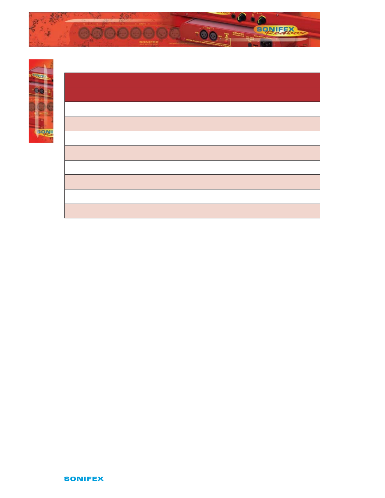
32
Redbox Embedder/De-embedder User Handbook
4
RBVHCMA4
RBVHCMA4
The Network connectors pin assignations are as follows:
Network Connector (RJ-45)
Pin No. Function
1 Transmit Data (Positive)
2 Transmit Data (Negative)
3 Receive Data (Positive)
4 No connection
5 No connection
6 Receive Data (Negative)
7 No connection
8 No connection
SDI Input
The SDI input is connected using a single female BNC and has a 75Ω input impedance. It is
a triple rate SDI receiver with automatic input rate detection and equalisation. It supports
the full range of 3G, SD and HD standards from NTSC and PAL up to 1080p 60Hz. The status
of the input is displayed on the status LEDs on the front panel. When the SDI input rate
and format has been detected, the SDI lock indicator will be lit.
SDI Outputs
The two SDI outputs are connected using the two female BNC connectors on the rear
panel. They have a 75Ω output impedance in accordance with the SMPTE standard and are
both re-clocked and independently buered. Each output can be congured separately for
embedding and group deletion settings.
Audio Connections
Analogue Audio Inputs
The RB-VHCMA4 has four analogue inputs grouped into a single embed bank. The
analogue inputs are converted to digital audio using high performance, low noise stereo
24-bit ADC’s. They are connected using balanced connections through the D-type
connectors or unbalanced connections through BNC connectors, all are available on the
rear panel. The balanced analogue inputs can be wired unbalanced by connecting nonphase (-) pin to the ground pin for that input, and then connecting the audio signal to the
phase (+) pin.
The two input types are connected internally, so please ensure that only one type of
connection is used per input.

Redbox Embedder/De-embedder User Handbook
33
4
RBVHCMA4
RBVHCMA4
Full Scale Setting
The analogue input full-scale settings, which determine the full-scale 0dBFS level for the
digital audio, are set internally via jumpers. They are factory set to +18dBu by default.
Full-scale Settings Jumper
JP1 JP2
+12dBu Not tted Not tted
+18dBu Fitted Not tted
+24dBu Not tted Fitted
Analogue Audio Outputs
The RB-VHCMA4 has four analogue outputs grouped into a single de-embed bank.
These can be connected using balanced connections through the D-type connectors or
unbalanced connections through BNC connectors, all are available on the rear panel. The
balanced analogue outputs can be wired unbalanced by connecting non-phase (-) pin to
the ground pin for that output, and then connecting the audio signal to the phase (+) pin.
The two output types are connected internally, so please ensure that only one type of
connection is used per output.
Full Scale Setting
The analogue output full-scale settings, which determine the full-scale 0dBFS level for the
digital audio, are set internally via jumpers. They are factory set to +18dBu by default.
Full-scale Settings Jumper
JP1 JP2
+12dBu Not tted Not tted
+18dBu Fitted Not tted
+24dBu Fitted Fitted
Audio Input and Output Gain Adjustment
The default audio channel gain is unity. However, to accommodate lower or higher level
sources it is possible to introduce gain or attenuation on a per channel basis. Each audio
channel has an adjustable gain range from -24dBu to +24dBu in 0.5dB increments. This is
set using the remote Control ports. Once set, this value is stored and reloaded each time
the unit is powered on.

34
Redbox Embedder/De-embedder User Handbook
4
RBVHCMA4
RBVHCMA4
RB-VHCMA4 D-type Pin-out
Pin No. Function
De-Embed Bank
Function
Embed Bank
1 Channel 1+ Channel 1+
14 Channel 1- Channel 1-
2 Channel 1 Ground Channel 1 Ground
15 Channel 2+ Channel 2+
3 Channel 2- Channel 2-
16 Channel 2 Ground Channel 2 Ground
4 Channel 3+ Channel 3+
17 Channel 3- Channel 3-
5 Channel 3 Ground Channel 3 Ground
18 Channel 4+ Channel 4+
6 Channel 4- Channel 4-
19 Channel 4 Ground Channel 4 Ground
7 to 13 Do not connect Do not connect
20 to 25 Do not connect Do not connect
Control Modes
There are two modes available to control the embedding and de-embedding channel
routing process. These are the BANK mode and the CHANNEL mode.
Bank Mode
In Bank mode, audio is routed on a per bank basis, so when controlling embedding, a bank
of audio is selected to be embedded into a group and when de-embedding a group of
audio is selected to be sent to a bank.
Channel Mode
In Channel mode, audio is routed on a per channel basis, this allows for maximum exibility
when embedding and de-embedding allowing any audio input channel to be embedded
to any channel within any group. And conversely, when de-embedding, any channel
within any group can be sent to any channel of any of the available audio output banks.

Redbox Embedder/De-embedder User Handbook
35
4
RBVHCMA4
RBVHCMA4
Changing Control Mode
To switch between Bank and Channel control modes, simultaneously press and hold
the GROUP CHANNEL and BANK CHANNEL buttons for 5 seconds. The mode will switch
after this time and the button can be released. Bank mode is in use when both the BANK
CHANNEL and GROUP CHANNEL button LEDs are not lit. Conversely, when Channel mode
is in use these two LEDs are lit.
When switching from Channel to Bank mode, all channel mappings are reset and no
groups are selected for embedding. When switching from Bank to Channel mode, the
channel mappings are retained to allow for further modication.
Embedding
The analogue audio inputs can be embedded into any of the four available groups in the
two SDI outputs. They can be embedded on a per bank basis in the Bank control mode, or
a per channel basis in the Channel control mode. If you embed to a group which is already
present in the SDI video input, then this group is automatically deleted from the video
input prior to the embedding block.
Bank Mode
To embed a bank of audio to a specic group.
Select the Embed bank, using the BANK button.
Select the SDI Output, using the STATUS button.
Select the group to embed to, using the GROUP button.
The GROUP button LED will indicate whether embedding is enabled to this group. To
enable embedding to this group, press and hold the GROUP button for two seconds, until
the button turns green. The group number LED will blink to indicate that the change
has been applied. This indicates that embedding is enabled to this group. To disable
embedding to this group, then hold the GROUP button down until the button turns red.
In this mode, the channels of the bank are mapped directly to the group channels. For
example channel 1 in the selected bank is embedded to channel 1 of the selected group.
Channel 2 in the selected bank is embedded to channel 2 of the selected group etc.
Cycling through the groups using the GROUP button, allows the user to determine which
groups are currently enabled for embedding and will also show the source for that group.
Channel Mode
To embed a channel of audio to a specic channel within a group.
1 Select the Embed bank, using the BANK button.
2 Select the SDI Output, using the STATUS button.
3 Select the bank channel using the the BANK CHANNEL button.
4 Select the group to embed to using the GROUP button.
5 Select the group channel to embed to using the GROUP CHANNEL button.

36
Redbox Embedder/De-embedder User Handbook
RBVHCMA4
4
RBVHCMA4
To enable embedding to this group and channel, both the GROUP and GROUP CHANNEL
must be enabled. This is indicated by the button LED being lit green. If either are red, then
simply enable them by holding down the relevant button for two seconds. Embedding will
only take place if the GROUP is enabled. If the GROUP CHANNEL is enabled and the GROUP
is not, then no embedding will occur.
Cycling through the groups and group channels using the GROUP and GROUP CHANNEL
buttons respectively, allows the user to determine which groups are currently enabled for
embedding and their sources.
SD & 24-bit Audio
The Redbox embedders provide full support for 24-bit audio embedding in SD by making
use of the extended data packets as per SMPTE-272M. By default the unit embeds 20-bit
audio. To enable the full 24-bit embedding, this must be set through the remote control
port.
Before enabling this option, ensure that any receiving equipment is capable of handling
the extended data packets.
De-Embedding
The unit is always de-embedding, automatically reading all the audio data contained in the
video signal as it appears to the de-embedding block. Using the front panel controls the
user can control which of these channels or groups within the video input are routed to the
analogue outputs.
If an SD video signal is being received and extended audio data is detected, then the unit
will automatically use this to reproduce full 24-bit audio data and no user intervention is
required.
Bank Mode
In bank mode de-embedding is controlled on a per group basis. So groups are selected to
be output on a particular bank.
To de-embed a group of audio to a specic bank.
1 Select the De-Embed bank, using the BANK button.
2 Select the group to de-embed using the GROUP button.
The BANK button LED will show whether the bank is enabled. To enable de-embedding to
this bank, press and hold the BANK button for two seconds, until the button turns green.
This indicates that de-embedding is enabled to this bank. To turn o de-embedding, then
hold the BANK button down until the button turns red. The bank number indicator will
blink to show that the change has been applied.
In this mode, the channels of the group are mapped directly to the bank channels. For
example channel 1 in the selected group is de-embedded to channel 1 of the selected
bank. Channel 2 in the selected group is de-embedded to channel 2 of the selected
bank etc.

Redbox Embedder/De-embedder User Handbook
37
4
RBVHCMA4
RBVHCMA4
Cycling through the banks using the BANK button, allows the user to determine which
banks are currently enabled for de-embedding and will also show the source group for that
bank.
Channel Mode
In channel mode, de-embedding is controlled on a per channel basis. So channels within a
group are selected to be output on a particular channel within a bank.
To de-embed a group channel of audio to a specic bank channel.
1 Select the De-Embed bank using the BANK button.
2 Select the output bank channel using the BANK CHANNEL button.
3 Select the group to de-embed using the GROUP button.
4 Select the group channel to de-embed using the GROUP CHANNEL button.
To enable de-embedding to this channel, both the BANK and BANK CHANNEL must be
enabled. This is indicated by the button LED being lit green. If either are red, then simply
enable them by holding down the relevant button for two seconds.
Cycling through the banks and bank channels using the BANK and BANK CHANNEL buttons
respectively, allows the user to determine which bank channels are currently enabled for
de-embedding and will also show the source for that bank channel.
Deleting Audio Groups
If the SDI video signal contains audio groups which require deleting, then these can be
deleted on a per output basis. For example if the video input contained all four audio
groups then it is possible to delete all groups on output 1 and only groups 1 and 2 on
output 2.
The unit will also delete any ancillary packets marked for deletion and realign the packets
to make maximum use of the available ancillary space.
To delete audio groups the unit is put into a special group deletion mode. To enter this
mode press and hold the STATUS button for 5 seconds. The front panel button indicators
will change so that only the GROUP, GROUP CHANNEL and STATUS buttons are available.
The GROUP button and indicators are used to select the group number, the GROUP
CHANNEL button is used to enable or disable deletion on this group and the STATUS
button is used to select the output. Once the desired settings have been set, then using
the same method to enter the group deletion mode will exit it. The new settings will be
applied as soon as the unit returns to its normal operating mode.

38
Redbox Embedder/De-embedder User Handbook
RBVHCMA4
4
RBVHCMA4
Technical Specication For RB-VHCMA4
Front Panel Controls & Indicators
Bank Select: De-embed bank or Embed bank
Bank Channel Select: Channels 1, 2, 3 or 4
Group Select: Groups 1, 2, 3 or 4
Group Channel Select: Group channels 1,2,3 or 4
Status: 1 x SDI input status LED
2 x SDI output LEDs
4 x Audio group status LEDs
Audio Specications
Analogue Inputs
Maximum Input Level: +27dBu (balanced)
Input Impedance: >10kΩ bridging (balanced)
Input Levels: +12dBu, +18dBu or +24dBu for FSD (jumper selectable)
Signal to Noise: Better than -113dBFS (RMS A-weighted at 24-bit, balanced)
Distortion and Impedance: Better than -100dB THD+N at 1kHz (balanced)
Analogue Outputs
Max Output Level: +24dBu (balanced)
Output Impedance: <50Ω (balanced)
Gain Range: 12dBu, 18dBu or 24dBu ref FSD (jumper selectable)
Signal to Noise: Better than -106dB (RMS A-weighted at 24-bit, balanced)
Distortion and Noise: Better than -85dB THD+N at 1kHz (balanced)
De-embed Delay: 3G/HD/SD: 1.1 ms
Embed Delay: SD: 600 us
3G/HD: 300 us
Connections
Analogue Audio Inputs: 4 input channels via BNC (unbalanced) or D-type (balanced)
Analogue Audio Outputs: 4 output channels via BNC (unbalanced
or D-type (balanced)

Redbox Embedder/De-embedder User Handbook
39
4
RBVHCMA4
RBVHCMA4
Analogue Audio Connectors: 8 x BNC
2 x 25-way D-type
Power Supply: Universal ltered IEC, continuously rated 85-264VAC
@47-63Hz, fused, max 16W
Equipment Type
RB-VHCMA4 3G/HD/SD-SDI embedder & de- embedder,
4 channel analogue I/O
Remote Interface Commands & Responses Protocol
Sonifex SCi remote control software handles all communication with the unit via a
convenient graphical user interface. However, this protocol is provided for those users who
wish to develop their own remote control applications or communicate with the unit using
a text-based terminal program.
Command Format
Commands are case-insensitive and should be terminated in a carriage return character, a
line feed character may be sent but it will be ignored. Further commands sent before the
rst command is acknowledged will be ignored. Responses will be CR & LF terminated.
Remote Control Commands
Command Description Response
COM:b,d,p,s Serial Port Settings
b is the baud rate (9600, 19200, 38400,
57600 and 115200)
d is the data bits (7 or 8)
p is the parity (N, O, E)
s is the stop bits (1 or 2)
ACK:
CTM:m Control Mode
m is the mode
0 = bank
1 = channel
ACK:
DEL:o,g,e Delete Audio Group
o is the output (0 or 1)
g is the group (0 to 3)
e is the option
0 = don’t delete
1 = delete
ACK:

40
Redbox Embedder/De-embedder User Handbook
4
RBVHCMA4
RBVHCMA4
Command Description Response
DWN: Initiates a Firmware Update
EMC:o,g,c,e Embed Group Channel Enable
This is only used when operating in
channel mode
o is the output (0 or 1)
g is the group (0 to 3)
c is the channel (0 to 3)
e is the option
0 = o
1 = on
ACK:
EMG:o,g,e Embed Group Enable
o is the output (0 or 1)
g is the group (0 to 3)
e is the option
0 = o
1 = on
ACK:
EMR:o,g[,gc],b[,bc] Embed Route Control
o is the output (0 or 1)
g is the group (0 to 3)
gc is the group channel (0 to 3) – only in
channel mode
b is the bank (0 or 1)
bc is the bank (0 to 3) – only in channel
mode
ACK:
DMC:b,c,e De-Embed Bank Channel Enable
This is only used when operating in
channel mode
b is the bank (0 to 3)
c is the channel (0 to 3)
e is the option
0 = o
1 = on
ACK:
DMB:b,e De-Embed Bank Enable
b is the group (0 to 3)
e is the option
0 = o
1 = on
ACK:

Redbox Embedder/De-embedder User Handbook
41
4
RBVHCMA4
RBVHCMA4
Command Description Response
DMR:b[,bc],g[,gc] De-Embed Route Control
b is the bank (0 to 3)
bc is the bank channel (0 to 3) – only in
channel mode
g is the group (0 to 3)
gc is the group channel (0 to 3) – only in
channel mode
ACK:
FPL:e Front Panel Lock
e is the enable option
0 = o
1 = on
ACK:
IPG:b,c,g Input Gain
b is the bank number (0 or 1)
c is the channel (0-3)
g is the gain value 0 to 96
0 = -24dBu and 96 = +24dBu
ACK:
MAC: MAC Address
Returns the MAC address of the unit in 12
hex characters.
MAC:XXXXXXXXXXXX
NET:x.x.x.x,y.y.y.y,z.z.z.z Network Address Settings
x.x.x.x is a valid IP address
y.y.y.y is a valid subnet mask
z.z.z.z is a valid gateway address
ACK:
NOP:o,v Network Options
o is the option number
0 = DHCP
v is the option value
0 = o
1 = on
ACK:
OPG:b,c,g Output Gain
b is the bank number (0 or 1)
c is the channel (0-3)
g is the gain value 0 to 96
0 = -24dBu and 96 = +24dBu
ACK:

42
Redbox Embedder/De-embedder User Handbook
RBVHCMA4
4
RBVHCMA4
Command Description Response
SDB:o,e SD Audio Sample Width
o is the output (0 or 1)
e is enable
0 = 20-bit
1 = 24-bit
ACK:
SRQ: Status Request
UID: Unit ID UID:RB-VHEMA8
VER: Version information
M1.m1.b1 is the Firmware version
M2.m2.b2 is the FPGA version
VER:M1.m1.b1, M2.m2.
b2

Redbox Embedder/De-embedder User Handbook
43
Digital
Outputs
Balanced
Unbalanced
Bank 1
Digital Audio
Transmitter
Channel
Routing
16
Channel
Level
Control
Bank 2
Digital Audio
Transmitter
Bank 3
Digital Audio
Transmitter
Bank 4
Digital
Audio TX
SDI
Input
SDI
Output 2
SDI
Receiver
Audio
De-embedder
Audio
Group Detect
Audio
Embedder
SDI
Transmitter
Audio
Pass /Delete
Audio
Embedder
SDI
Transmitter
Audio
Pass /Delete
EQ CD
SDI
Output 1
CD
16
Channel
Level
Control
Channel
Routing
Bank 1
Digital Audio
RX+SRC
Bank 2
Digital Audio
RX+SRC
Bank 3
Digital Audio
RX+SRC
Bank 4
Digital Audio
RX+SRC
Digital
Inputs
Balanced
Unbalanced
4
4
4
4
16
4
4
4
4
16
5
RBVHCMD16
RBVHCMD16
5 RB-VHCMD16 3G/HD/SD-SDI Embedder & De-Embedder
16 Channel Digital I/O
The RB-VHCMD16 is a 16 channel de-embedder and 16 channel embedder combined into
a single 19-inch rack unit. The unit can selectively de-embed any channel within any audio
group of an SDI video signal, to any of the digital outputs. After which, the video becomes
two independent paths where the audio groups can be selectively deleted or passed
through. The unit then embeds any of the digital input channels to available groups within
each of the two video paths, which are then sent to the re-clocked SDI outputs.
The de-embedding and embedding channel routing is controlled via the front panel
buttons and indicators. There is also LED indication for SDI input status and audio group
presence.
The unit can be remote controlled via Ethernet or serial port connections using the Sonifex
SCi software.
It has a triple rate SDI receiver with automatic input rate detection and equalisation along
with two re-clocked and individually buered SDI outputs. It supports the full range of 3G,
HD and SD standards from NTSC and PAL up to 1080p 60Hz.
Each digital input is normally sample rate converted to 48kHz before embedding, so that
it is synchronous to the video input. Though sample rate conversion can be bypassed on a
per input basis allowing SMPTE-337M data to be embedded. All digital outputs are output
at 48kHz, synchronous to the video input.
There is independent level control for each digital input and output channel, which can be
adjusted from -24dB through to +24dB in 0.5dB steps.
The digital audio I/O connections are transformer-coupled balanced line interfaces and can
be congured through SCi to be either 75Ω (AES 3ID) or 110Ω (AES 3) impedance through
either a BNC or via the D-type connector. These connections are paralleled, allowing one
type to be used per input or output.
System Block Diagram
Fig 5-1: RB-VHCMD16 System Block Diagram

44
Redbox Embedder/De-embedder User Handbook
INTRODUCTION
RBVHCMD16
5
Front Panel Indicators & Controls
Fig 5-2: RB-VHCMD16 Front Panel
Power LED
The POWER LED illuminates whilst internal power is present within the unit. If this indicator
is not on, the most likely reason is simply the absence of mains power, but under fault
conditions it may also indicate a ruptured mains fuse or a problem with the internal power
supply module.
Reset Button
In the unlikely event that the unit fails to respond, press the reset button to reboot the unit.
Bank
Embed
The BANK button and its associated indicators are used to select the audio input bank
when controlling the embedding channel routing.
De-Embed
The BANK button and its associated indicators are used to select the audio output bank
when controlling the de-embedding channel routing. The button LED is used show
whether the bank is enabled. To enable or disable the bank, press and hold the BANK
button for two seconds until the bank number indicator blinks. When lit green it is enabled
and when it is lit red it is disabled. When the bank is disabled, all audio outputs are muted.
Bank Channel
Embed
The BANK CHANNEL button and its indicators are only used when the unit is operating in
Channel mode and are used to select the audio input bank channel when controlling the
embedding channel routing.
De-Embed
The BANK CHANNEL button and its indicators are only used when the unit is operating in
Channel mode and are used to select the audio output bank channel when controlling the
de-embedding channel routing. The button LED is used to show whether the channel is
enabled. To enable or disable the channel, press and hold the BANK CHANNEL button for
two seconds until the channel number indicator blinks. When lit green it is enabled and
when it is lit red it is disabled. When the channel is disabled, the audio output is muted.
The channel will also be muted if the bank is disabled, even if the channel is enabled.
Power
LED
BANK
Button
BANK
Channel
GROUP
Button
GROUP
Channel
STATUS
Button
FUNCTION
Button

Redbox Embedder/De-embedder User Handbook
45
RBVHCMD16
5
RBVHCMD16
Function Button
This button is used to select between embedding or de-embedding control.
Group
Embed
The GROUP button and its indicators are used to select the group number with which to
embed the analogue input channels to. The button LED is used show whether embedding
is enabled to the currently selected group. To enable or disable the embedding to a group,
press and hold the GROUP button for two seconds until the group number indicator blinks.
When lit green it is enabled and when it is lit red it is disabled. When the group is disabled,
no embedding is done to that group number.
De-Embed
The GROUP button and its indicators are used to select the group audio number within the
video signal to de-embed and send to digital outputs in the currently selected bank.
Group Channel
Embed
The GROUP CHANNEL and its indicators are used to select the channel within the currently
selected group with which to embed the digital input channel to. This button is only used
when operating in Channel mode. The button LED is used show whether the channel
is enabled for embedding. To enable or disable the channel, press and hold the GROUP
CHANNEL button for two seconds until the channel number indicator blinks. When lit
green it is enabled and when it is lit red it is disabled. When the channel is disabled, no
audio is embedded to that channel. The channel will also not be embedded if the group is
not enabled for embedding, even if the channel is enabled.
De-Embed
The GROUP CHANNEL button and its indicators are used to select the channel number
within the currently selected group to de-embed and send to the digital output in the
currently selected bank and bank channel. This button is only used when operating in
Channel mode.
Status
This button is used to select the output number when controlling the embedding routing.
It is also used to enter and exit the group deletion mode.
Audio Group Detection
The four audio group indicators associated with the STATUS button display the audio
groups present in the SDI input. If an audio group is present, its relevant indicator will be
lit. This is useful to determine which groups require deleting or which groups are available
for embedding.
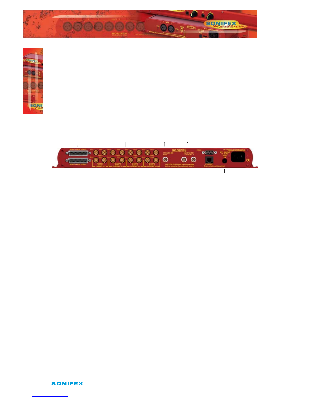
46
Redbox Embedder/De-embedder User Handbook
INTRODUCTION
RBVHCMD16
5
Lock Indicator
The lock indicator is lit when the the SDI receiver has detected and locked to the incoming
video format. If the input is disconnected or is intermittent then the lock indicator will stay
unlit.
Output Indicators
These two indicators are used to indicate which one of the two outputs are selected when
conguring the embedding routing or when conguring audio packets for deletion.
Rear Panel Connections
Fig 5-3: RB-VHCMD16 Rear Panel
Mains Power
Power is applied via a standard three-pin IEC male socket. Mains voltages between 85V
and264V AC and frequencies between 47 and 63Hz are accepted without adjustment. A
2A, 5 x 20mm SB fuse is used. The Earth pin MUST be connected to ensure safety.
Remote Control
The unit can be controlled remotely either by serial RS-232 or Ethernet using the Sonifex
SCi software. Using remote control allows the user to monitor the status of the unit and
also set various options and settings not available via the front panel.
PowerRS232
Ethernet Fuse
AES D-Type
I/O
AES BNC
I/O
SDIINSDI Outputs
1 and 2
Redbox Embedder/De-embedder User Handbook
47
5
RBVHCMD16
RBVHCMD16
RS232 Remote Control
A 9-way female D-type connector carries a standard RS232 interface via which advanced
conguration options may be set and many functions may be remotely controlled. The pin
assignations are as follows:
Pin No. Function
1 Unused
6 Unused
2 Data transmit (TX)
7 Unused
3 Data receive (RX)
8 Unused
4 Unused
9 Unused
5 Ground
The RB-VHCMD16 will interface directly with personal computer serial ports at standard
RS232 signal levels using a straight-through cable. The default format is 19200 baud with 8
data bits, even parity and 1 stop bit. Sonifex SCi software, when installed on a suitable PC,
provides straightforward graphical access to all remote control and conguration options
via both RS232 and Ethernet interfaces. Alternatively, commands may be issued from any
text-based terminal program (e.g. Hyperterminal) or custom software may be developed
for specic requirements.
Ethernet
The Ethernet port is connected using a standard RJ-45 connector on the rear of the panel.
It is a 10/100Mbps link. The unit is shipped with DHCP enabled to allow the unit to be
plug and play if the users local area network has a DHCP server. If one is not available on

48
Redbox Embedder/De-embedder User Handbook
INTRODUCTION
RBVHCMD16
5
the network and the unit cannot retrieve a valid IP address after 45 seconds it will default
to a static address. This static address is set to 192.168.0.100 by default but can be altered
through SCi using the serial port connection. If DHCP is not required then this can also be
disabled through SCi using the serial port connection.
The Network connectors pin assignations are as follows:
Network Connector (RJ-45)
Pin No. Function
1 Transmit Data (Positive)
2 Transmit Data (Negative)
3 Receive Data (Positive)
4 No connection
5 No connection
6 Receive Data (Negative)
7 No connection
8 No connection
SDI Input
The SDI input is connected using a single female BNC and has a 75Ω input impedance. It is
a triple rate SDI receiver with automatic input rate detection and equalisation. It supports
the full range of 3G, SD and HD standards from NTSC and PAL up to 1080p 60Hz. The status
of the input is displayed on the status LEDs on the front panel. When the SDI input rate
and format has been detected, the SDI lock indicator will be lit.
SDI Outputs
The two SDI outputs are connected using the two female BNC connectors on the rear
panel. They have a 75Ω output impedance in accordance with the SMPTE standard and are
both re-clocked and independently buered. Each output can be congured separately for
embedding and group deletion settings.
Audio Connections
Digital Audio Inputs & Outputs
The RB-VHCMD16 has sixteen channels of audio inputs and outputs grouped into four
banks each with four input channels of inputs and four output channels.
The digital audio I/O connections are transformer-coupled balanced line interfaces and
can be congured through SCi to be either 75Ω (AES 3ID) or 110Ω (AES 3) input or output
impedance through either a BNC or via the D-type connector. These connections are
paralleled, allowing one type to be used per input or output.

Redbox Embedder/De-embedder User Handbook
49
RBVHCMD16
5
RBVHCMD16
The digital inputs are sample rate converted to 48kHz so that the audio is synchronous to
the video input signal. This can be disabled via a remote control option.
The digital outputs are always output at 48kHz and will be synchronous to the video signal.
No sample rate conversion is applied to the digital outputs.
Audio Input and Output Gain Adjustment
The default audio channel gain is unity. However, to accommodate lower or higher level
sources it is possible to introduce gain or attenuation on a per channel basis. Each audio
channel has an adjustable gain range from -24dBu to +24dBu in 0.5dB increments. This is
set using the remote Control ports. Once set, this value is stored and reloaded each time
the unit is powered on.
Automatic Dolby Detection & SMPTE-337M Support
Each digital input is sample rate converted by default so that it is synchronous to the
incoming video signal. But if a digital audio signal contains non-linear PCM data such as
Dolby E or Dolby Digital, then this process will corrupt the data and render it unusable.
In addition to this if any gain or attenuation is applied to this channel, the eect will be
similar. To provide support for these types of signals and any other non-audio data the
units will automatically detect non-audio data and bypass the SRC and gain sections as
soon as it is detected. This method relies on the channel status bits being correct, but
there is also an option to bypass the SRC on a per input basis regardless of the signal
content. The user must ensure that unity gain is applied through the gain section in this
case so that the data is passed through unaected.
Note that for correct embedding of non-audio data, the digital audio input must be
synchronous to the video signal prior to the embedder unit.
RB-VHCMD16 D-type Pin-out
Pin No. Function
I/O Bank 1
Function
I/O Bank 2
1 Digital 1 In+ Digital 5 In+
14 Digital 1 In- Digital 5 In-
2 Digital 1 In Ground Digital 5 In Ground
15 Digital 1 Out+ Digital 5 Out+
3 Digital 1 Out- Digital 5 Out-
16 Digital 1 Out Ground Digital 5 Out Ground
4 Digital 2 In+ Digital 6 In+
17 Digital 2 In- Digital 6 In-
50
Redbox Embedder/De-embedder User Handbook
RBVHCMD16
RBVHCMD16
5
5 Digital 2 In Ground Digital 6 In Ground
18 Digital 2 Out+ Digital 6 Out+
6 Digital 2 Out- Digital 6 Out-
19 Digital 2 Out Ground Digital 6 Out Ground
7 Digital 3 In+ Digital 7 In+
20 Digital 3 In- Digital 7 In-
8 Digital 3 In Ground Digital 7 In Ground
21 Digital 3 Out+ Digital 7 Out+
9 Digital 3 Out- Digital 7 Out-
22 Digital 3 Out Ground Digital 7 Out Ground
10 Digital 4 In+ Digital 8 In+
23 Digital 4 In- Digital 8 In-
11 Digital 4 In Ground Digital 8 In Ground
24 Digital 4 Out+ Digital 8 Out+
12 Digital 4 Out- Digital 8 Out-
25 Digital 4 Out Ground Digital 8 Out Ground
13 Do not connect Do not connect
Control Modes
There are two modes available to control the embedding and de-embedding channel
routing process. These are the BANK mode and the CHANNEL mode.
Bank Mode
In Bank mode, audio is routed on a per bank basis, so when controlling embedding, a bank
of audio is selected to be embedded into a group and when de-embedding a group of
audio is selected to be sent to a bank.
Channel Mode
In Channel mode, audio is routed on a per channel basis, this allows for maximum exibility
when embedding and de-embedding allowing any audio input channel to be embedded
to any channel within any group. And conversely, when de-embedding, any channel within
any group can be sent to any channel of any of the available audio output banks.
Changing Control Mode
To switch between Bank and Channel control modes, simultaneously press and hold
the GROUP CHANNEL and BANK CHANNEL buttons for 5 seconds. The mode will switch
after this time and the button can be released. Bank mode is in use when both the BANK

Redbox Embedder/De-embedder User Handbook
51
5
RBVHCMD16
RBVHCMD16
CHANNEL and GROUP CHANNEL button LEDs are not lit. Conversely, when Channel mode
is in use these two LEDs are lit.
When switching from Channel to Bank mode, all channel mappings are reset and no
groups are selected for embedding. When switching from Bank to Channel mode, the
channel mappings are retained to allow for further modication.
Embedding
The audio inputs can be embedded into any of the four available groups in the two SDI
outputs. They can be embedded on a per bank basis in the Bank control mode, or a per
channel basis in the Channel control mode. If you embed to a group which is already
present in the SDI video input, then this group is automatically deleted from the video
input prior to the embedding block.
Bank Mode
To embed a bank of audio to a specic group.
1 Select the Embed function using the FUNCTION button.
2 Select the SDI output using the STATUS button.
3 Select the bank of audio using the BANK button.
4 Select the group to embed to, using the GROUP button.
The GROUP button LED will indicate whether embedding is enabled to this group. To
enable embedding to this group, press and hold the GROUP button for two seconds, until
the button turns green. The group number LED will blink to indicate that the change
has been applied. This indicates that embedding is enabled to this group. To disable
embedding to this group, then hold the GROUP button down until the button turns red.
In this mode, the channels of the bank are mapped directly to the group channels. For
example channel 1 in the selected bank is embedded to channel 1 of the selected group.
Channel 2 in the selected bank is embedded to channel 2 of the selected group etc.
Cycling through the groups using the GROUP button, allows the user to determine which
groups are currently enabled for embedding and will also show the source for that group.
Channel Mode
To embed a channel of audio to a specic channel within a group.
1 Select the Embed function using the FUNCTION button.
2 Select the SDI Output, using the STATUS button.
3 Select the bank of audio using the BANK button.
4 Select the bank channel using the the BANK CHANNEL button.
5 Select the group to embed to using the GROUP button.
6 Select the group channel to embed to using the GROUP CHANNEL button.

52
Redbox Embedder/De-embedder User Handbook
RBVHCMD16
RBVHCMD16
5
To enable embedding to this group and channel, both the GROUP and GROUP CHANNEL
must be enabled. This is indicated by the button LED being lit green. If either are red, then
simply enable them by holding down the relevant button for two seconds. Embedding will
only take place if the GROUP is enabled. If the GROUP CHANNEL is enabled and the GROUP
is not, then no embedding will occur.
Cycling through the groups and group channels using the GROUP and GROUP CHANNEL
buttons respectively, allows the user to determine which groups are currently enabled for
embedding and their sources.
SD & 24-bit Audio
The Redbox embedders provide full support for 24-bit audio embedding in SD by making
use of the extended data packets as per SMPTE-272M. By default the unit embeds 20-bit
audio. To enable the full 24-bit embedding, this must be set through the remote control
port.
Before enabling this option, ensure that any receiving equipment is capable of handling
the extended data packets.
De-Embedding
The unit is always de-embedding, automatically reading all the audio data contained in the
video signal as it appears to the de-embedding block. Using the front panel controls the
user can control which of these channels or groups within the video input are routed to the
analogue outputs.
If an SD video signal is being received and extended audio data is detected, then the unit
will automatically use this to reproduce full 24-bit audio data and no user intervention is
required.
Bank Mode
In bank mode de-embedding is controlled on a per group basis. So groups are selected to
be output on a particular bank.
To de-embed a group of audio to a specic bank.
1 Select the De-Embed function using the FUNCTION button.
2 Select the audio bank, using the BANK button.
3 Select the group to de-embed using the GROUP button.
The BANK button LED will show whether the bank is enabled. To enable de-embedding to
this bank, press and hold the BANK button for two seconds, until the button turns green.
This indicates that de-embedding is enabled to this bank. To turn o de-embedding, then
hold the BANK button down until the button turns red. The bank number indicator will
blink to show that the change has been applied.
In this mode, the channels of the group are mapped directly to the bank channels. For
example channel 1 in the selected group is de-embedded to channel 1 of the selected
bank. Channel 2 in the selected group is de-embedded to channel 2 of the selected
bank etc.

Redbox Embedder/De-embedder User Handbook
53
RBVHCMD16
5
RBVHCMD16
Cycling through the banks using the BANK button, allows the user to determine which
banks are currently enabled for de-embedding and will also show the source group for that
bank.
Channel Mode
In channel mode, de-embedding is controlled on a per channel basis. So channels within a
group are selected to be output on a particular channel within a bank.
To de-embed a group channel of audio to a specic bank channel.
1 Select the De-Embed function using the FUNCTION button.
2 Select the audio bank using the BANK button.
3 Select the output bank channel using the BANK CHANNEL button.
4 Select the group to de-embed using the GROUP button.
5 Select the group channel to de-embed using the GROUP CHANNEL button.
To enable de-embedding to this channel, both the BANK and BANK CHANNEL must be
enabled. This is indicated by the button LED being lit green. If either are red, then simply
enable them by holding down the relevant button for two seconds.
Cycling through the banks and bank channels using the BANK and BANK CHANNEL buttons
respectively, allows the user to determine which bank channels are currently enabled for
de-embedding and will also show the source for that bank channel.
Deleting Audio Groups
If the SDI video signal contains audio groups which require deleting, then these can be
deleted on a per output basis. For example if the video input contained all four audio
groups then it is possible to delete all groups on output 1 and only groups 1 and 2 on
output 2.
The unit will also delete any ancillary packets marked for deletion and realign the packets
to make maximum use of the available ancillary space.
To delete audio groups the unit is put into a special group deletion mode. To enter this
mode press and hold the STATUS button for 5 seconds. The front panel button indicators
will change so that only the GROUP, GROUP CHANNEL and STATUS buttons are available.
The GROUP button and indicators are used to select the group number, the GROUP
CHANNEL button is used to enable or disable deletion on this group and the STATUS
button is used to select the output. Once the desired settings have been set, then using
the same method to enter the group deletion mode will exit it. The new settings will be
applied as soon as the unit returns to its normal operating mode.

54
Redbox Embedder/De-embedder User Handbook
RBVHCMD16
RBVHCMD16
5
Technical Specication For RB-VHCMD16
Front Panel Controls & Indicators
Bank Select: Bank 1, 2, 3 or 4
Bank Channel Select: Channels 1, 2, 3 or 4
Function Select: De-embed or embed
Group Select: Groups 1, 2, 3 or 4
Group Channel Select: Group channels 1,2,3 or 4
Status: 1 x SDI input status LED
2 x SDI output LEDs
4 x Audio group status LEDs
Audio Specications
Output Sample Rate: 48kHz
Input Sample Rates: 32-192kHz, sample rate converted to 48kHz. SRC can
be bypassed.
Input & Output Impedance: 75Ω/110Ω selectable
Signal Level Unbalanced: 1Vp-p ±20%
(un-terminated): Balanced: 6.6Vp-p ±20%
Dynamic Range: 138dB
Distortion and Noise: <-137dB THD+N at 997Hz, ref 0dBFS Connections
De-embed Delay: 3G/HD/SD: 330 us
SRC Input Delay: 192 kHz: 1.3 ms
96 kHz: 1.83 ms
48 kHz: 2.9 ms
Embed Delay: SD: 600 us + SRC Input Delay
3G/HD: 300 us + SRC Input Delay
Digital Audio Outputs: 16 outputs via 8 BNCs or D-type (AES3)
Digital Audio Inputs: 16 inputs via 8 BNCs or D-type (AES3 )
Digital Audio Connectors: 16 x BNC
2 x 25-way D-type socket
Power Supply: Universal ltered IEC, continuously rated 85-264VAC
@47-63Hz, fused, max 13W
Equipment Type
RB-VHCMD16 3G/HD/SD-SDI embedder & de- embedder 16 channel
digital I/O

Redbox Embedder/De-embedder User Handbook
55
5
RBVHCMD16
RBVHCMD16
Remote Interface Commands & Responses Protocol
Sonifex SCi remote control software handles all communication with the unit via a
convenient graphical user interface. However, this protocol is provided for those users who
wish to develop their own remote control applications or communicate with the unit using
a text-based terminal program.
Command Format
Commands are case-insensitive and should be terminated in a carriage return character, a
line feed character may be sent but it will be ignored. Further commands sent before the
rst command is acknowledged will be ignored. Responses will be CR & LF terminated.
Remote Control Commands
Command Description Response
BOP:b,o,v Bank Option
b is the bank
o is the option
0 = SRC Disable for input channels 1/2
1 = SRC Disable for input channels 3/4
2 = Input channels 1/2 Termination
3 = Input channels 3/4 Termination
4 = Output channels 1/2 Termination
5 = Output channels 3/4 Termination
v is the option value
0 = o
1 = on
ACK:
COM:b,d,p,s Serial Port Settings
b is the baud rate (9600, 19200, 38400,
57600 and 115200)
d is the data bits (7 or 8)
p is the parity (N, O, E)
s is the stop bits (1 or 2)
ACK:
CTM:m Control Mode
m is the mode
0 = bank
1 = channel
ACK:
DEL:o,g,e Delete Audio Group
o is the output (0 or 1)
g is the group (0 to 3)
e is the option
0 = don’t delete
1 = delete
ACK:
DWN: Initiates a Firmware Update

56
Redbox Embedder/De-embedder User Handbook
RBVHCMD16
RBVHCMD16
5
Command Description Response
EMC:o,g,c,e Embed Group Channel Enable
This is only used when operating in
channel mode
o is the output (0 or 1)
g is the group (0 to 3)
c is the channel (0 to 3)
e is the option
0 = o
1 = on
ACK:
EMG:o,g,e Embed Group Enable
o is the output (0 or 1)
g is the group (0 to 3)
e is the option
0 = o
1 = on
ACK:
EMR:o,g[,gc],b[,bc] Embed Route Control
o is the output (0 or 1)
g is the group (0 to 3)
gc is the group channel (0 to 3) – only
in channel mode
b is the bank (0 or 1)
bc is the bank (0 to 3) – only in channel
mode
ACK:
DMC:b,c,e De-Embed Bank Channel Enable
This is only used when operating in
channel mode
b is the bank (0 to 3)
c is the channel (0 to 3)
e is the option
0 = o
1 = on
ACK:
DMB:b,e De-Embed Bank Enable
b is the group (0 to 3)
e is the option
0 = o
1 = on
ACK:

Redbox Embedder/De-embedder User Handbook
57
5
RBVHCMD16
RBVHCMD16
Command Description Response
DMR:b[,bc],g[,gc] De-Embed Route Control
b is the bank (0 to 3)
bc is the bank channel (0 to 3) – only in
channel mode
g is the group (0 to 3)
gc is the group channel (0 to 3) – only
in channel mode
ACK:
FPL:e Front Panel Lock
e is the enable option
0 = o
1 = on
ACK:
IPG:b,c,g Input Gain
b is the bank number (0 or 1)
c is the channel (0-3)
g is the gain value 0 to 96
0 = -24dBu and 96 = +24dBu
ACK:
MAC: MAC Address
Returns the MAC address of the unit in
12 hex characters.
MAC:XXXXXXXXXXXX
NET:x.x.x.x,y.y.y.y,z.z.z.z Network Address Settings
x.x.x.x is a valid IP address
y.y.y.y is a valid subnet mask
z.z.z.z is a valid gateway address
ACK:
NOP:o,v Network Options
o is the option number
0 = DHCP
v is the option value
0 = o
1 = on
ACK:
OPG:b,c,g Output Gain
b is the bank number (0 or 1)
c is the channel (0-3)
g is the gain value 0 to 96
0 = -24dBu and 96 = +24dBu
ACK:

58
Redbox Embedder/De-embedder User Handbook
RBVHCMD16
RBVHCMD16
5
Command Description Response
SDB:o,e SD Audio Sample Width
o is the output (0 or 1)
e is enable
0 = 20-bit
1 = 24-bit
ACK:
SRQ: Status Request
UID: Unit ID UID:RB-VHEMA8
VER: Version information
M1.m1.b1 is the Firmware version
M2.m2.b2 is the FPGA version
VER:M1.m1.b1, M2.m2.b2

Redbox Embedder/De-embedder User Handbook
59
6
COMMON SPECIFICATION
COMMON SPECIFICATION
6 Common Specications For RB-VHEMA8, RB-VHDMA8,
RB-VHCMA4 & RB-VHCMD16
SDI Specication
SDI Input: 1 x BNC, 3G/HD/SD-SDI
SDI Outputs: 2 x BNC, 3G/HD/SD-SDI, Re-clocked
Impedance: 75Ω
Output Alignment Jitter: <0.2UI (3G <0.3UI)
Output Level: 800mV +/- 10%
Return Loss: <15dB at 1500MHz
SDI Supported Standards: 270Mbps, SMPTE-259M-C (SD)
1.485 or 1.4835Gbps, SMPTE-292M (HD)
2.97 or 2.967Gbps, SMPTE-424M (3G), SMPTE-425M-A
Supported Video Formats: 525/59.94 (SMPTE-125M)
625/50 (ITU-R BT.656)
720p/23.98, 24, 25, 29.97, 30, 50, 59.94, 60 (SMPTE-296M)
1035i/59.94, 60 (SMPTE-260M)
1080i/50, 59.94, 60 (SMPTE-274M)
1080p/23.98, 24, 25, 50, 59.94, 60 (SMPTE-274M)
1080pSF/23.98, 24, 25, 29.97, 30 (RP-211)
1080i/50 (SMPTE-295M)
1080p/50 (SMPTE-295M)
Video Delay: SD: 290 pixels / 22 us
HD: 570 pixels / 8 us
3G: 570 pixels / 4 us
Video Delay Control: 525/59.94 0 to 55 frames
625/50 0 to 46 frames
1080p/50 0 to 8 frames
1080p/59.94,60 0 to 10 frames
720p/23.98, 24, 25
1080i/50
1080p/23.98,24,25 0 to 16 frames
720p/29.97, 30
1035i/59.94, 60
1080i/59.94, 60
1080p/29.97,30 0 to 20 frames
720p/50 0 to 33 frames
720p/59.94, 60 0 to 40 frames
Embedded Audio: 24-bit, 48kHz synchronous
SMPTE-272M-C
SMPTE-299M

60
Redbox Embedder/De-embedder User Handbook
COMMON SPECIFICATION
6
COMMON SPECIFICATION
Serial Port: RS232, 9 way D-type
Ethernet Port: 10/100Mbps, RJ-45
Fuse Rating: Anti-surge fuse 2A 20 x 5mm
Physical Specications
Dimensions (Raw): 48cm (W) x 10.8cm (D*) x 4.2cm (H) (1U)
19” (W) x 4.3” (D*) x 1.7” (H) (1U)
Dimensions (Boxed): 59cm (W) x 27.5cm (D) x 11cm (H)
23.2” (W) x 10.8” (D) x 4.3” (H)
Weight: Nett: 1.8kg Gross: 2.3kg
Nett: 4.0lb Gross: 5.1lb
* Note that this product is deeper than standard Redboxes

Redbox Embedder/De-embedder User Handbook
61
SCI
SCI
7
7 SCi
System Page
Fig 7-1: SCi System Screen
This page is used for the connecting and disconnecting SCi to the unit, updating the rmware
in the units, displaying the current status of the unit and controlling various settings.
Status
Video Input
Shows the current SDI input rate, video format and the audio groups status. When an audio
group is detected in the incoming stream the status is set to PRESENT, and MISSING when that
group is not detected.
Video Output 1 & 2
The two video output status boxes show the audio group status for each output.There are
three states per output and these are described below.
PASS : This audio group is being passed through on this output.
EMBED : This audio group is being embedded on this output.
DELETE : This audio group is being deleted on this output.

62
Redbox Embedder/De-embedder User Handbook
SCI
7
SCI
Admin Connection
This displays any connection which has “Administrator” rights to the unit.
Network Status
This displays the current network settings assigned to the unit.
Settings
General
Front Panel Lock
When selected, this control disables the front panel and prohibits any changes to be made
via the front panel. This control is automatically disabled when the unit is powered on.
Channel Control
Enables/Disables the channel control mode.
Front Panel LED Brightness
Increases or decreases the LED intensity on the front panel.
Restore Defaults
Pressing this button will cause the unit to restore all settings to their factory defaults. All
previous settings will be lost. Note: The login details are not reset and are unaected by
this process.
Fig 7-2: Network Settings
Network
Enable DHCP
This enables the unit to receive it’s IP address, subnet mask and gateway settings from a
DHCP server. If one is not available then this should be disabled through the serial port and
a valid static address be entered.
Note: This setting cannot be changed while connected to the unit over Ethernet.
IP Address: Displays the current IP address of the unit. If DHCP is enabled then this will
normally be the IP address supplied by the DHCP server.
Subnet Mask: Displays the current subnet mask for the unit.

Redbox Embedder/De-embedder User Handbook
63
7
SCI
SCI
Default gateway: Displays the current default gateway for the unit.
Note: The units are discovered using broadcast packets. If your PC has two network cards,
then there is a limitation in windows that requires the two addresses to be on dierent
subnet addresses.
Updating The Firmware
The rmware will occasionally be updated to add new features or correct any possible
issues that may arise. Check for updates at: http://www.sonifex.co.uk/technical/software
To update the rmware click on the button labeled “Update Firmware” and then select the
downloaded rmware le. Firmware les will always have an “.dwn or dw2” extension. A
progress bar will appear in SCi, indicating how much of the le has been uploaded to the
unit.
When the unit switches to update mode, the unit will continue to operate as normal but
the front panel will become locked. The progress of the update will be displayed on screen
and once complete the unit will return to it’s previous state and operate as normal. To
complete the update the unit must be restarted. Only then will the update be complete.
De-Embed Page
Fig 7-3: SCi De-Embed Screen

64
Redbox Embedder/De-embedder User Handbook
SCI
7
SCI
This page allows you to congure the group sources for each of the available De-Embed
banks on the unit. This page is not available on the RB-VHEMA8 unit.
When in bank control mode, only the top group selection box is available for each bank.
This selects the group to de-embed to all the channels in that bank.
When in channel control mode, all of the selection boxes become available, allowing you
to individually select a group and channel for each output.
Bank Enable: This control enables the bank for De-Embedding.
Group/Channel: Selects the group and/or channel for De-Embedding to the bank.
Enable: Individually enables each channel within the bank. Only used in channel control
mode.
Embed Page
Fig 7-4: SCi Embed Screen
The two Embed pages allow you to control embedding for each SDI output. These pages
are not available on the RB-VHDMA8 unit.
When in bank control mode, only the top bank selection box is available for each group.
This selects the bank to embed to all the channels in that group and then channel
assignments are shown in the channel selection boxes.

Redbox Embedder/De-embedder User Handbook
65
SCI
7
SCI
When in channel control mode, all of the bank and channel selection boxes become
available, allowing you to individually select a bank and channel to embed to each group
channel.
Embed Enable: This control enables embedding for the selected group.
Bank/Channel: Selects the Embed bank and/or channel to embed to the group.
Enable: Individually enables each channel within the group. Only used in channel control
mode.
Audio Group Delete
Allows the deletion of audio groups on a per output basis. Simply select the group to
enable deletion.
SD 24-Bit Enable: This enables 24-bit embedding in SD. This is selectable on a per output
basis. Before enabling this option, ensure that any receiving equipment is capable of
handling the extended data packets.
Audio Inputs Page
Fig 7-5: SCi Audio Inputs Screen
This page allows you to congure the audio inputs for the available Embed banks. This
page is not available on the RB-VHDMA8 unit.

66
Redbox Embedder/De-embedder User Handbook
SCI
7
SCI
Gain Slide Bars: Controls the input gain or attenuation for each input channel. Can be set
from -24 dB to +24 dB in 0.5 dB steps. Double clicking the gain value label at the bottom of
the slide bar will set the gain to 0 dB.
Link: If selected, the gain slide bars are linked together so that changing one will change
the others in that bank.
SRC Disable: Only available on the RB-VHCMD16, these controls allow you to disable
sample rate conversion on each input.
Termination: Only available on the the RB-VHCMD16, these controls select the input
termination from between 75 and 110Ω.
Audio Outputs Page
Fig 7-6: SCi Audio Outputs Screen
This page allows you to congure the audio outputs for the available De-Embed banks.
This page is not available on the RB-VHEMA8 unit.
Gain Slide Bars: Controls the output gain or attenuation for each output channel. Can
be set from -24 dB to +24 dB in 0.5 dB steps. Double clicking the gain value label at the
bottom of the slide bar will set the gain to 0 dB.
Link: If selected, the gain slide bars are linked together so that changing one will change
the others in that bank.

Redbox Embedder/De-embedder User Handbook
67
SCI
7
SCI
Termination: Only available on the the RB-VHCMD16, these controls select the output
termination from between 75 and 110Ω.
Delay Page
Fig 7-7: SCi Delay Screen
This page allows control over the video delay through the unit. This control is only
available in the newer units running rmware V2.X.X or greater.
The amount of delay through the unit can be expressed in either lines or frames. The
maximum number of which is determined by the current video format being received by
the unit. When the input rate changes the maximum delay value is updated.
Mode: Selects between Line or Frame delay mode.
Delay Edit: This is where the actual delay valued can be entered. This value is represented
on the slide bar below, which can also be altered to congure the delay value.
Current Delay: This label displays the current delay value active in the unit.

68
Redbox Embedder/De-embedder User Handbook
GLOSSARY
GLOSSARY
8
8 Glossary
AES Audio Engineering Society.
Attenuation The reduction of a signal level. Attenuation is usually measured
in dB.
Balanced Audio A way of sending audio over cable that protects it from induced
interference
BNC Bayonet Neill-Concelman connector.
Clipping The onset of severe distortion in the signal path, usually caused
by the peak signal voltage being limited.
dB (decibel) A ratio of two voltages or signal levels, expressed by the
equation.
dB=20LOG(V1/V2).
Adding the sux “u” denotes that the signal is relative to 0.775V
RMS. Adding the sux “v” denotes that the signal is relative to
1V RMS.
Adding the sux “FS” denotes that the signal is relative to the
maximum value of a digital signal.
DHCP Dynamic Host Conguration Protocol is a computer networking
protocol used to retrieve IP address and other conguration
information from a server.
EBU European Broadcast Union
FSD Full Scale Digits - This is the analogue representation of the
maximum digital value that the converter in question can see
before digital clipping occurs.
Gain The degree of amplication, or attenuation, applied to a signal.
IEC International Elecrotechnical Commision - often used to refer to
a mains connectivity standard, i.e. A type of plug/socket similar
to that of a kettle, used on most pro-audio equipment.
ITU International Telecommunication Union.
kHz Kilo Hertz (One thousand cycles per second).

Redbox Embedder/De-embedder User Handbook
69
GLOSSARY
8
GLOSSARY
LAN Local Area Network - scheme where several computers on the
same
premises are connected together so that they can exchange
data.
LED Light Emitting Diode (small lights e.g. on computers).
MHz Mega-hertz - One million cycles per second.
NTSC National Television System Committee.
PAL Phase Alternating Line.
PSU Power Supply Unit
SDI Serial Digital Interface. A digital video interface standardised by
SMPTE.
SMPTE Society of Motion Picture and Television Engineers.
SRC Sample Rate Converter.
TCP/IP Transmission Control Protocol / Internet Protocol. Computer
interconnection methodology used on the internet and LANs.
THD The Total Harmonic Distortion is the percentage presence of
signals
outside the measured reference frequency.
U A height measurement for rack-mount equipment:
1U = 1.75 inches
2U = 3.5 inches
3U = 5.25 inches
4U = 7 inches
SD Standard Denition video.
HD High Denition video
3G 3Gpbs High Denition video.

70
Redbox Embedder/De-embedder User Handbook
NOTES
NOTES

Redbox Embedder/De-embedder User Handbook
71
NOTES
NOTES

www.sonifex.co.uk
t:+44 (0)1933 650 700
f:+44 (0)1933 650 726
sales@sonifex.co.uk
 Loading...