


HANDBOOK
Redbox
User Handbook No 1
RB-ADDA Combined A/D and D/A Converter (24 bit, 96kHz
Capable) (1U)
RB-ADDA2 Combined A/D and D/A Converter (24 bit, 192kHz
Capable) (1U)
RB-SC1 Sample Rate Converter (24 bit, 96kHz Capable)
RB-SC2 Dual Sample Rate Converter (24 bit, 192kHz
Capable)
RB-DAC1 Digital to Analogue Converter
RB-SP1 Digital Splitter & Combiner
RB-SYA Analogue Video Sync Board For RB-SC2 (PAL,
NTSC, SECAM)
RB-SYD Digital Video Sync Board For RB-SC2 (HD-SDI,
SD-SDI)
RB-SYE AES/EBU Sync Board For RB-TGHD(B or X)
RB-SYW Word Clock Sync Board
RB-DS2 Stereo Delay Synchroniser & Time-Zone Delay
(1U)
RB-DS2R Remote Switch Panel For RB-DS2 (1U)
RB-PD2 Stereo Profanity Delay (1U)
RB-DD4 4 Channel Digital Audio Delay Synchroniser (1U)
RB-AEC Acoustic Echo Canceller (1U)
Manufacturers of audio & video
products for radio & TV broadcasters

Redbox Handbook 1
For the latest Sonifex handbook information please visit the
Sonifex website at www.sonifex.co.uk
This handbook is for use with the following product:
Redbox User Handbook No 1
Stock Code: 30-335
Artwork: AW10838
Revision 3.05, September 2019
x Ltd, 2019
©Sonife
All Rights Reserved
Sonifex Ltd, 61, Station Road, Irthlingborough,
Northants, NN9 5QE, England.
Tel: +44 (0)1933 650 700
Fax: +44 (0)1933 650 726
Email: sales@sonifex.co.uk
Website: https://www.sonifex.co.uk
Information in this document is subject to change without notice and does not represent a
commitment on the part of the vendor. Sonifex Ltd shall not be liable for any loss or damage
whatsoever arising from the use of information or any error contained in this manual.
No part of this manual may be reproduced or transmitted in any form or by any means, electronic
or mechanical, including photocopying, recording, information storage and retrieval systems, for any
purpose other than the purchaser’s personal use, without the express written permission of Sonifex
Ltd. Unless otherwise noted, all names of companies, products and persons contained herein are
part of a completely fictitious adaptation and are designed solely to document the use of Sonifex
product.
Made in the UK by

Contents
Contents
Product Warranty - 2 Year Extended ii
Sonifex Warranty & Liability Terms & Conditions ii
1. Definitions ii
2. Warranty ii
Unpacking Your Product iii
Repairs & Returns iv
Conformity iv
Safety & Installation of Mains Operated Equipment iv
Voltage Setting Checks iv
Fuse Rating iv
Power Cable & Connection iv
WEEE Directive v
Atmosphere/Environment v
Fitting Redboxes v
1 RB-ADDA Combined A/D and D/A Converter 1
Introduction 1
System Block Diagram 2
Front Panel Indicators 2
Rear Panel Connections and Operation 2
Technical Specifications RB-ADDA 6
2 RB-ADDA2 Combined A/D and D/A Converter 24bit 192kHz 7
Introduction 7
System Block Diagram 9
Front Panel Controls & Indicators 9
Rear Panel Connections and Operation 10
Serial Port Control 12
Serial Interface Commands and Responses 12
Upgrading Firmware 14
Technical Specifications RB-ADDA2 14
3 RB-SC1 Sample Rate Converter 16
Introduction 16
System Block Diagram 16
Front Panel Indicators 17
Rear Panel Connections and Operation 17
Technical Specifications RB-SC1 19
4 RB-SC2 Dual Sample Rate Converter 21
Introduction 21
Installing the Optional Video Sync Boards 23
Opening the RB-SC2 23
System Block Diagram 24
Front Panel Controls & Indicators 25
Rear Panel Connections and Operation 26
Serial Port Control 27
Serial Interface Commands and Responses 27
Upgrading Firmware 28
Technical Specification RB-SC2 29
5 RB-DAC1 Digital to Analogue Converter 30
Introduction 30
System Block Diagram 30
Front Panel Indicators & Controls 31
Rear Panel Connections and Operation 31
Technical Specifications RB-DAC1 33
6 RB-SP1 Digital Splitter & Combiner 34
Introduction 34
System Block Diagram 34
Front Panel Indicators & Controls 35
Rear Panel Connections and Operation 36
Technical Specifications RB-SP1 38
7 Redbox - Synchronisation Add-On Boards 39
Introduction 39
RB-SYA Analogue Video Sync Board 39
RB-SYD Digital Video Sync Board 39
RB-SYE Sync Board 40
RB-SYW Sync Board 40
8 RB-DS2 Stereo Delay Synchroniser & Time Zone Delay 41
Introduction 41
Extended Mode using Compact Flash™ 42
System Block Diagram 43
Front Panel Controls 43
Rear Panel Connections and Operation 44
The Default Screen 46
The Main Menu 46
Serial Port Control 51
Serial Interface Commands and Responses 51
Upgrading Firmware 53
Technical Specifications RB-DS2 53
Opening the RB-DS2 to Add a Compact Flash Card 54

Contents
9 RB-DS2R Remote Switch Panel For RB-DS2 58
Introduction 58
Technical Specification For RB-DS2R 59
10 RB-PD2 Stereo Profanity Delay 60
Introduction 60
System Block Diagram 61
Quickstart Guide 62
Front Panel Controls 64
Rear Panel Connections 66
The Default Screen 68
The Main Menu 68
Review Mode 74
Serial Port Control 75
Serial Interface Commands and Responses 75
Upgrading Firmware 78
Technical Specification RB-PD2 79
11 RB-DD4 4 Channel Digital Audio Delay 80
Front Panel Controls and Indicators 81
Delay Button Modes 83
Rear Panel Controls & Connectors 84
Rear Panel DIPSwitches 84
RB-DD4 Inputs 86
RB-DD4 Outputs 87
Serial Port Control 87
Serial Interface Commands and Responses 87
SCi for the RB-DD4 91
Status Page 91
Unit Setup Page 92
Miscellaneous Page 93
Updating the Firmware 93
Technical Specification For RB-DD4 94
12 RB-AEC Acoustic Echo Canceller 96
Introduction 96
Category 96
Product Function 96
Typical Applications 96
Features 96
Operation of the RB-AEC 97
Front Panel Controls and Indicators 99
Rear Panel Connections and Controls 99
Inputs 99
Outputs 99
Mains Power 101
Applications 102
How to Remove Delayed Presenter’s Audio From Their
Earpiece 102
The Problem: 102
The Solution: 102
How to Remove Delayed Caller Audio From
The Telephone Line 103
The Problem: 103
The Solution: 103
Calibration 104
Webserver & Unit Discovery 104
Home Page 105
Far End and Near End Input Type 105
Adaption Status 105
Network Page 108
Network Settings 108
Device Info Page 109
Update Page 110
Technical Specification For RB-AEC 111

Figures
Figures
Fig A: RB-RK1Small Redbox Front Rack-mount Kit . v
Fig B: RB-RK2 Small Redbox Rear Rack-mount Kit. vi
Fig C: RB-RK3 Large Redbox Rear Rack-mount Kit. vi
Fig 1-1: RB-ADDA Front Panel 1
Fig 1-2: RB-ADDA System Block Diagram 2
Fig 1-3: RB-ADDA Rear Panel 2
Fig 1-4: RB-ADDA Full Scale dB Settings 4
Fig 1-5: RB-ADDA Status Select Switches 4
Fig 1-6: RB-ADDA Frequency and Sync Rotary Switch 5
Fig 2-1: RB-ADDA2 Front Panel 7
Fig 2-2: RB-ADDA2 System Block Diagram 9
Fig 2-3: SYNC Button & LEDs 9
Fig 2-4: A/D SOURCE Select Button & LEDs 9
Fig 2-5: FREQUENCY Set Button & LEDs 9
Fig 2-6: CS DATA Button & LEDs 10
Fig 2-7: BITS Button & LEDs 10
Fig 2-8: D/A SOURCE Select Button & LEDs 10
Fig 2-9: RB-ADDA2 Rear Panel 10
Fig 3-1: RB-SC1 Front Panel 16
Fig 3-2: RB-SC1 System Block Diagram 16
Fig 3-3: RB-SC1 Rear Panel 17
Fig 3-4: RB-SC1 Status Switches 18
Fig 3-5: RB-SC1 Frequency and Sync Rotary Switch Settings 19
Fig 4-1: RB-SC2 Front Panel 21
Fig 4-2: RB-SC2 X-Lock Sync Mode 22
Fig 4-3: RB-SC2 Optional Video Sync Installation 23
Fig 4-4: RB-SC2 System Block Diagram 24
Fig 4-5: FREQUENCY Set Button & LEDs 25
Fig 4-6: CS DATA Button & LEDs 25
Fig 4-7: INPUT 1 & INPUT2 Source Select Button & LEDs 25
Fig 4-8: SYNC Button & LEDs 25
Fig 4-9: RB-SC2 Rear Panel 26
Fig 4-10: Serial Port Default Settings 27
Fig 4-11: Serial Interface Commands and Responses 28
Fig 5-1: RB-DAC1 Front Panel 30
Fig 5-2: RB-DAC1 System Block Diagram 30
Fig 5-3: RB-DAC1 Front Panel 31
Fig 5-4: RB-DAC1 Rear Panel 31
Fig 5-5: RB-DAC1 Full Scale Digits and De-emphasis
Settings Switches 32
Fig 6-1: RB-SP1 Front Panel 34
Fig 6-2: RB-SP1 System Block Diagram 34
Fig 6-3: RB-SP1 Front Panel 35
Fig 6-4: RB-SP1 Type and Mode Flow Diagrams 36
Fig 6-5: RB-SP1 Rear Panel 36
Fig 6-6: RB-SP1 Mode Select Dip Switches 37
Fig 7-1: RB-SYA Analogue Video Sync Board For RB-SC2
(PAL, NTSC, SECAM) 39
Fig 7-2: RB-SYD Digital Video Sync Board For RB-SC2
(HD-SDI, SD-SDI) 39
Fig 7-3: RB-SYE Sync Board 40
Fig 7-4: RB-SYW Sync Board 40
Fig 8-1: RB-DS2 Front Panel 41
Fig 8-2: RB-DS2 System Block Diagram 43
Fig 8-3: Front Panel CONTROL 43
Fig 8-4: RB-DS2 Rear Panel 44
Fig 8-5: The Default Screen 46
Fig 8-6: The Main Menu 46
Fig 8-7: Maximum Delays in Normal Mode
(Using On-Board Memory Only) 55
Fig 8-8: Maximum Delays in Extended FAT Mode with 1 GB
Compact Flash™ Memory Card Installed 56
Fig 8-9: Maximum Delays in Extended RAW Mode with 16 GB
Compact Flash™ Memory Card Installed. 57
Fig 9-1: RB-DS2R Front Panel 58
Fig 9-2: RB-DS2R Rear Panel 58
Fig 10-1: RB-PD2 Front Panel 60
Fig 10-2: RB-PD2 System Block Diagram 61
Fig 10-3: RB-PD2 Rotary Control Operation 64
Fig 10-4: RB-PD2 Front Panel Buttons 65
Fig 10-5: RB-PD2 Rear Panel 66
Fig 10-6: The Default Screen 68
Fig 10-7: The Main Menu Screen 68
Fig 10-8: The Record Screen 71
Fig 11-1: RB-DD4 Front Panel 80
Fig 11-2: RB-DD4 Block Diagram 81
Fig 11-3: Front Panel Controls and Indicators 81

Figures
Fig 11-4: DELAY Button 82
Fig 11-5: CHANNEL SELECT Button 82
Fig 11-6: INPUTS 1 & 2 Button 82
Fig 11-7: MONITOR SELECT Button 82
Fig 11-8: Headphone Output & Level Controls 83
Fig 11-9: Reset Button 83
Fig 11-10: Minimum delay values (at 0 frames) due to
inherent delay at different input to output
sample rates within the unit, measured in ms 84
Fig 11-11: RB-DD4 Rear Panel DIPSwitch Block 84
Fig 11-12: RB-DD4 Rear Panel 84
Fig 11-13: Serial Port Default Settings 87
Fig 11-14: Status Page 91
Fig 11-15: Unit Setup Page 92
Fig 11-16: Miscellaneous Page 93
Fig 12-1: The RB-AEC Acoustic Echo Canceller 96
Fig 12-2: The RB-AEC Operational Block Diagram 97
Fig 12-3: The RB-AEC Functional Block Diagram 98
Fig 12-4: The RB-AEC Front Panel 99
Fig 12-5: The RB-AEC Rear Panel 100
Fig 12-6: The RB-AEC Sonifex Service Discovery Tool 104
Fig 12-7: The RB-AEC Webserver Interface - Home 105
Fig 12-8: The RB-AEC Webserver Interface - Configuration 106
Fig 12-9: The RB-AEC Webserver Interface - Network 108
Fig 12-10: The RB-AEC Webserver Interface - Device Info 109
Fig 12-11: The RB-AEC Webserver Interface - Update 110

Warranty Registration
Register Online for an
Extended 2 Year Warranty
As standard, Sonifex products are
supplied with a 1 year back to base
warranty.
If you register the product online, you
can increase your product warranty
to 2 years and we can also keep
you informed of any product design
improvements or modifications.
To register your product, please go online to www.sonifex.co.uk/register
Sonifex Limited y 61 Station Road y Irthlingborough y Northamptonshire y NN9 5QE y United Kingdom
Tel: +44 (0)1933 650 700 y Fax: +44 (0)1933 650 726 y Email: technical.support@sonifex.co.uk y Internet: www.sonifex.co.uk
Product:
Serial No:

Warranty
Product Warranty - 2 Year Extended
As standard, Sonifex products are supplied with a 1 year back to base
warranty. In order to register the date of purchase and so that we can keep
you informed of any product design improvements or modifications, it is
important to complete the warranty registration online. Additionally, if you
register the product on the Sonifex website, you can increase your product
warranty to 2 years. Go to the Sonifex website at: https://www.sonifex.
co.uk/technical/register/index.asp to apply for your 2 year warranty.
Note: For your own records the product serial number is recorded on the
CE certification page of this handbook.
Sonifex Warranty & Liability Terms & Conditions
1. Definitions
‘the Company’ means Sonifex Ltd and where relevant includes companies
within the same group of companies as Sonifex Limited.
‘the Goods’ means the goods or any part thereof supplied by the Company
and where relevant includes: work carried out by the Company on items
supplied by the Purchaser; services supplied by the Company; and software
supplied by the Company.
‘the Purchaser’ means the person or organisation who buys or has agreed
to buy the Goods.
‘the Price’ means the Price of the Goods and any other charges incurred by
the Company in the supply of the Goods.
‘the Warranty Term’ is the length of the product warranty which is usually
12 months from the date of despatch; except when the product has been
registered at the Sonifex website when the Warranty Term is 24 months
from the date of despatch.
‘the Contract’ means the quotation, these Conditions of Sale and any
other document incorporated in a contract between the Company and the
Purchaser.
This is the entire Contract between the parties relating to the subject
matter hereof and may not be changed or terminated except in writing in
accordance with the provisions of this Contract. A reference to the consent,
acknowledgement, authority or agreement of the Company means in
writing and only by a director of the Company.
2. Warranty
a. The Company agrees to repair or (at its discretion) replace Goods
e found to be defective (fair wear and tear excepted) and
which ar
which are returned to the Company within the Warranty Term
provided that each of the following are satisfied:
i. notification of any defect is given to the Company immediately
upon its becoming apparent to the Purchaser;
ii. the Goods have only been operated under normal operating
conditions and have only been subject to normal use (and
in particular the Goods must have been correctly connected
and must not have been subject to high voltage or to ionising
radiation and must not have been used contrary to the
Company’s technical recommendations);
iii. the Goods are returned to the Company’s premises at the
Purchaser’s expense;
iv. any Goods or parts of Goods replaced shall become the
property of the Company;
v. no work whatsoever (other than normal and proper
maintenance) has been carried out to the Goods or any part of
the Goods without the Company’s prior written consent;
ii

Warranty
vi. the defect has not arisen from a design made, furnished or
specified by the Purchaser;
vii. the Goods have been assembled or incorporated into other
goods only in accordance with any instructions issued by the
Company;
viii. the defect has not arisen from a design modified by the
Purchaser;
ix. the defect has not arisen from an item manufactured by a person
other than the Company. In respect of any item manufactured
by a person other than the Company, the Purchaser shall only be
entitled to the benefit of any warranty or guarantee provided by
such manufacturer to the Company.
b. In respect of computer software supplied by the Company the
Company does not warrant that the use of the software will be
uninterrupted or error free.
c. The Company accepts liability:
(i) for death or personal injury to the extent that it results from the
negligence of the Company, its employees (whilst in the course
of their employment) or its agents (in the course of the agency);
(ii) for any breach by the Company of any statutory undertaking as
to title, quiet possession and freedom from encumbrance.
d. Subject to conditions (a) and (c) from the time of despatch of
the Goods from the Company’s premises the Purchaser shall be
responsible for any defect in the Goods or loss, damage, nuisance
or interference whatsoever consequential economic or otherwise or
wastage of material resulting from or caused by or to the Goods. In
particular the Company shall not be liable for any loss of profits or
other economic losses. The Company accordingly excludes all liability
for the same.
e. At the request and expense of the Purchaser the Company will test
the Goods to ascertain performance levels and provide a report of
the results of that test. The report will be accurate at the time of the
test, to the best of the belief and knowledge of the Company, and the
Company accepts no liability in respect of its accuracy beyond that
set out in Condition (a).
f. Subject to Condition (e) no representation, condition, warranty or
other term, express or implied (by statute or otherwise) is given by
the Company that the Goods are of any particular quality or standard
or will enable the Purchaser to attain any particular performance
or result, or will be suitable for any particular purpose or use
under specific conditions or will provide any particular capacity,
notwithstanding that the requirement for such performance, result or
capacity or that such particular purpose or conditions may have been
known (or ought to have been known) to the Company, its employees
or agents.
g. (i) To the extent that the Company is held legally liable to the
Purchaser for any single breach of contract, tort, representation
or other act or default, the Company’s liability for the same
shall not exceed the price of the Goods.
(ii) The restriction of liability in Condition (g)(i) shall not apply to
any liability accepted by the Seller in Condition (c).
h. Where the Goods are sold under a consumer transaction (as defined
by the Consumer Transactions (Restrictions on Statements) Order
1976) the statutory rights of the Purchaser are not affected by these
Conditions of Sale.
Unpacking Your Product
Each product is shipped in protective packaging and should be inspected
for damage before use. If there is any transit damage take pictures of the
product packaging and notify the carrier immediately with all the relevant
iii

CE Conformity
details of the shipment. Packing materials should be kept for inspection and
also for if the product needs to be returned.
The product is shipped with the following equipment so please check to
ensure that you have all of the items below. If anything is missing, please
contact the supplier of your equipment immediately.
Item Quantity
Product unit 1
IEC mains lead fitted with moulded mains plug 1
Handbook and warranty card 1
If you require a different power lead, please let us know when ordering the
product.
Repairs & Returns
Please contact Sonifex or your supplier if you have any problems with your
Sonifex product. Email technical.support@sonifex.co.uk for the repair/
upgrade/returns procedure, or for support & questions regarding the
product operation.
Conformity
The products in this manual comply with the essential requirements of the
relevant European health, safety and environmental protection legislation.
The technical justification file for this product is available at Sonifex Ltd.
The declaration of conformity can be found at:
https://www.sonifex.co.uk/declarations
Safety & Installation of Mains
Operated Equipment
There are no user serviceable parts inside the equipment. If you should ever
need to look inside the unit, always disconnect the mains supply before
removing the equipment covers. The cover is connected to earth by means of
the fixing screws. It is essential to maintain this earth/ground connection to
ensure a safe operating environment and provide electromagnetic shielding.
Voltage Setting Checks
Ensure that the machine operating voltage is correct for your mains power
supply by checking the box in which your product was supplied. The voltage
is shown on the box label. The available voltage settings are 115V, or 230V.
Please note that all products are either switchable between 115V and 230V,
or have a universal power supply.
Fuse Rating
The product is supplied with a single fuse in the live conducting path of the
mains power input. For reasons of safety it is important that the correct
rating and type of fuse is used. Incorrectly rated fuses could present a
possible fire hazard, under equipment fault conditions. The active fuse is
fitted on the outside rear panel of the unit.
Power Cable & Connection
An IEC power connector is supplied with the product which has a moulded
plug attached.
The mains plug or IEC power connector is used as the disconnect device.
The mains plug and IEC power connector shall remain readily operable to
disconnect the apparatus in case of a fault or emergency.
The mains lead is automatically configured for the country that the product is
being sent to, from one of:
iv
Safety & Installation
Territory Voltage IEC Lead Type Image
UK & Middle East 230V UK 3 pin to IEC lead
Europe 230V
USA, Canada and
South America
Australia & New
Zealand
Connect the equipment in accordance with the connection details and
before applying power to the unit, check that the machine has the correct
operating voltage for your mains power supply.
This apparatus is of a class I construction. It must be connected to a mains
socket outlet with a protective earthing connection.
Important note: If there is an earth/ground terminal on the rear panel of
the product then it must be connected to Earth.
European Schuko round 2 pin to
IEC lead
115V 3 flat pin to IEC lead
230V Australasian 3 flat pin to IEC lead
WEEE Directive
The Waste Electrical and Electronic Equipment (WEEE)
Directive was agreed on 13 February 2003, along with the
related Directive 2002/95/EC on Restrictions of the use of
certain Hazardous Substances in electrical and electronic
equipment (RoHS). The Waste Electrical and Electronic Equipment Directive
(WEEE) aims to minimise the impacts of electrical and electronic equipment
on the environment during their life times and when they become waste.
All products manufactured by Sonifex Ltd have the WEEE directive label
placed on the case. Sonifex Ltd will be happy to give you information about
local organisations that can reprocess the product when it reaches its “end
of use”, or alternatively all products that have reached “end of use” can be
returned to Sonifex and will be reprocessed correctly free of charge.
Atmosphere/Environment
This apparatus should be installed in an area that is not subject to excessive
temperature variation (<0°C, >50°C), moisture, dust or vibration.
This apparatus shall not be exposed to dripping or splashing, and no objects
filled with water, such as vases shall be placed on the apparatus.
Fitting Redboxes
Redboxes can be fixed to the underside of a desk, or other surfaces
using 4.2mm holes in the sides and fixed with 2 x M4 screws or 2 x No. 6
countersink wood screws.
Fig A: RB-RK1Small Redbox Front Rack-mount Kit .
v

Safety & Installation
They can also be rack-mounted, with either the front, or rear of the Redbox positioned at the front of the rack (Note: this product is front rack-mounted as
standard):
Front Mounting Redboxes: For rack mounting smaller (28cm) units the optional RB-RK1 (Red) or RB-RK1B (Black) kit can be used (which include
4 off M6 panel fixing screws).
Rear Mounting a Redbox: For rear panel mounting you can use either the RB-RK2 (in this case), or RB-RK3, depending on the size of your Redbox.
Fig B: RB-RK2 Small Redbox Rear Rack-mount Kit.
Fig C: RB-RK3 Large Redbox Rear Rack-mount Kit.
vi

1 RB-ADDA Combined A/D and D/A Converter
Introduction
Digital Audio Converters - RB- ADDA 1
Fig 1-1: RB-ADDA Front Panel
Using 24 bit, 96kHz capable devices, the RB-ADDA A/D and D/A Converter
is a 1U rack-mount which produces an AES/EBU or S/PDIF level digital audio
output from a balanced XLR or unbalanced phono stereo audio input. The
unit also produces a stereo balanced XLR or unbalanced phono output from
an incoming AES/EBU or S/PDIF digital input signal.
The unit operates in four modes:
Master Mode - In this mode the unit receives an analogue
audio signal, which is digitised and formatted for digital serial
transmission (IEC958). The necessary clock signals
are generated internally from an on board master clock at a selectable rate
(32kHz, 44.1kHz, 48kHz, 64kHz, 88.1kHz or 96kHz).
Slave Mode - In this mode the unit automatically detects the presence of a
digital audio sync signal, if present at the digital input, and synchronises the
digital output to it. If no sync is present, no output will be generated.
Auto Mode - Here the unit synchronises to the digital audio sync signal
if present at the digital input and uses the internal master clock only if no
sync input signal is detected. In this case, the internal master clock is used
at the selected sample rate.
Auto Lock Mode - This operates like the auto mode. The difference is that
if the sync input signal is lost, the unit will revert to an internal master clock
rate as near as possible to the last sync signal received.
When operating in sync modes, the front panel power LED flashes
whenever the unit is not synchronised to the incoming digital signal, or
when the unit is being calibrated. The RB-ADDA should be calibrated once it
has been powered up for more than 10 minutes.
The analogue inputs have left and right level controls using pre-set
potentiometers and DIP switches allowing a signal range from +9dBu to
+27dBu. The analogue outputs have an output level control, allowing
full-scale settings selectable from +12dBu, +18dBu or +24dBu. There are
factory-set internal level controls for the analogue outputs allowing gain
adjustment of ±1dB.
There are buttons to select either the AES/EBU or S/PDIF input or output
for the D/A and A/D sections respectively. The output bit depth can be
selected from 16, 20 or 24 bits. Inputs of a different bit depth to the output
are dithered using a psychoacoustic noise filter.
For the digital output, there is a switch available to define the content of
the channel status bits embedded within the digital audio stream. The
channel status bits can be set to either Professional or Consumer Mode.
1

1 Digital Audio Converters - RB- ADDA
System Block Diagram
Fig 1-2: RB-ADDA System Block Diagram
Front Panel Indicators
The LED on the front panel is normally red to indicate that power is present
on the unit. However, it also has a secondary role to indicate the status of
the digital inputs
Fast flashing between red and amber – indicates a loss of digital input signal
or that the unit is being calibrated.
RCA Phono
Inputs
XLR Analogue Inputs XLR Analogue Outputs AES/EBU Output Status Select Switches
Fig 1-3: RB-ADDA Rear Panel
2
RCA Phono
Outputs
Digital Select Button Digital Select Button
Rear Panel Connections and Operation
RB-ADDA Inputs
XLR Analogue Inputs (Left and Right)
The XLR 3 pin sockets used for the left and right channel inputs are
ĞůĞĐƚƌŽŶŝĐĂůůLJďĂůĂŶĐĞĚĂŶĚŚĂǀĞĂŶŝŵƉĞĚĂŶĐĞŽĨŐƌĞĂƚĞƌƚŚĂŶϭϬŬɏ
bridging. Each XLR has the following connections:
AES/EBU
Input
S/PDIF
Input & Output
Frequency & Synch
Mode Rotary Switch
Digital Audio Converters - RB- ADDA 1
Pin 1: Screen.
Pin 2: Phase.
Pin 3: Non-phase.
RCA Phono Inputs (Left and Right)
The two left and right RCA inputs are unbalanced and have an impedance of
ŐƌĞĂƚĞƌƚŚĂŶϮϬŬɏ
Input Level Adjustment
The input gain can be individually adjusted for left and right channels by
dipswitches and through pre-set potentiometers accessible on the rear
panel. For full scale dB settings refer to Fig 1-4.
Individual preset pots give a further ± 3dBu to give a total gain range of
+9dBu to +27dBu for full-scale digits. The consumer input on the phono
connector has a further 10dbU gain incorporated to give a total gain range
of -1dBu to +17dBu for full-scale digits.
AES/EBU Inputs
dŚĞĚŝŐŝƚĂůŝŶƉƵƚy>ZϯƉŝŶƐŽĐŬĞƚŚĂƐĂŶŝŵƉĞĚĂŶĐĞŽĨϭϭϬɏ/ƚŚĂƐƚŚĞ
following connections:
Pin 1: Screen
Pin 2: Phase
Pin 3: Non-phase
The signals on this connector should meet the IEC 60968 specification
S/PDIF Inputs
dŚĞ^W/&ĚŝŐŝƚĂůƉŚŽŶŽŝŶƉƵƚƐŚĂǀĞĂŶŝŵƉĞĚĂŶĐĞŽĨϳϱɏ
RB-ADDA Outputs
Analogue Outputs (Left and Right)
The XLR 3 pin output plug connectors are electronically balanced with an
ŽƵƚƉƵƚŝŵƉĞĚĂŶĐĞŽĨůĞƐƐƚŚĂŶϱϬɏdŚĞLJŚĂǀĞƚŚĞĨŽůůŽǁŝŶŐĐŽŶŶĞĐƚŝŽŶƐ
Pin 1: Screen.
Pin 2: Phase.
Pin 3: Non-phase.
RCA Phono Outputs (Left and Right)
These RCA (phono) outputs are unbalanced and have an output impedance
ŽĨůĞƐƐƚŚĂŶϳϱɏ
Output Level Adjustment
The output gain can be individually adjusted for left and right channels
through the rear panel by dipswitches. Each output gain can be set for a
signal of full-scale digits in the digital domain to give +12, +18 or +24dBu
output on the XLR connectors (see Fig 1-4). The consumer output on the
phono connector has a further 10dbU attenuation incorporated.
AES/EBU Output
dŚĞĚŝŐŝƚĂůŽƵƚƉƵƚy>ZϯƉŝŶƐŽĐŬĞƚŚĂƐĂŶŝŵƉĞĚĂŶĐĞŽĨϭϭϬɏ/ƚŚĂƐƚŚĞ
following connections:
Pin 1: Screen
Pin 2: Phase
Pin 3: Non-phase
The signals on this connector will comply with the IEC 60968 specification
S/PDIF Output
dŚĞĚŝŐŝƚĂůŽƵƚƉƵƚ^W/&ƉŚŽŶŽŽƵƚƉƵƚŚĂƐĂŶŝŵƉĞĚĂŶĐĞŽĨϳϱɏ
Rear Panel Controls
Full Scale dB Settings
The full-scale dB settings can be set for signals of +12, +18, +24 dBu to give
full-scale digits in the digital domain.
Analogue (A/D) Input
Full Scale Setting
(dBu)
+12 OFF OFF
+18 ON OFF
+24 ON ON
Switch 1 Switch 2
3

1 Digital Audio Converters - RB- ADDA
Analogue (D/A)
Switch 3 Switch 4
Output Full Scale
Setting (dBu)
+12 OFF OFF
+18 ON OFF
+24 ON ON
Fig 1-4: RB-ADDA Full Scale dB Settings
Status Select Switches
These switches are used to determine the status or content of the digital
signals. The type of information encoded in the channel status bits of a
digital audio signal can be professional or consumer and is determined by
switch 1.
If de-emphasis is selected (switch 2) the RB-ADDA will decode 50/15μs
emphasis when indicated by certain channel status bits in the incoming
digital audio data.
The sample size for the analog to digital conversion can be set to 24, 20 or
16 bits (switch 3 & 4). When the signal is truncated from 24 bits, a psychoacoustic filter is applied to maintain optimum signal quality. These settings
are summarised by the table in Fig 1-5, which is also shown on the top
panel of the unit.
Status Bits
1 ON Professional 16 20 24
1 OFF Consumer 3 OFF OFF ON
2 ON De-emphasis On 4 OFF ON ON
2 OFF De-emphasis Off
Fig 1-5: RB-ADDA Status Select Switches
Digital Select Buttons
These buttons are used to switch the digital connection between the AES/
EBU XLR connector (button out) and the S/PDIF phono connector (button
in) for the digital input and the digital output.
Analogue Select Button
This button is used to switch the Analogue input between the balanced XLR
connector (button out) and the unbalanced phono connector (button in).
Frequency and Sync Mode Rotary Switch
This rotary switch is used to select the Synchronisation Mode and to
select the frequency of the digital output when using the on-board clock
generator. There are 4 modes of operation: - Master Mode, Auto Sync
Mode, Auto Lock Sync Mode & Slave Mode.
In Master Sync Mode, switch positions 0 – 5, the digital output sample rate
is simply set by, and locked to, the internal on-board clock generator. No
sync signal is used or required.
In Auto Sync Mode, switch positions 6– B, the digital output sample rate
follows the digital input. When the digital input signal is not present the
output sample rate will be set by, and locked to, the internal on-board clock
generator at a frequency determined by the switch position.
In Auto-Lock Sync Mode, switch position C, No output will be generated
until lock is achieved with a digital input signal. The digital output sample
rate now follows the digital input. If the digital input signal is removed then
the output sample rate will be set by, and locked to, the internal on-board
clock generator at the closest frequency available to the previous digital
input.
In Slave Sync Mode, switch position D, the digital output sample rate
follows the digital input. When the digital input signal is not present the
digital output is turned off.
4

Digital Audio Converters - RB- ADDA 1
The following table, also printed on the top of the unit, summarises the
above settings and shows the sample rate generated by the internal clock
generator in master and auto sync modes.
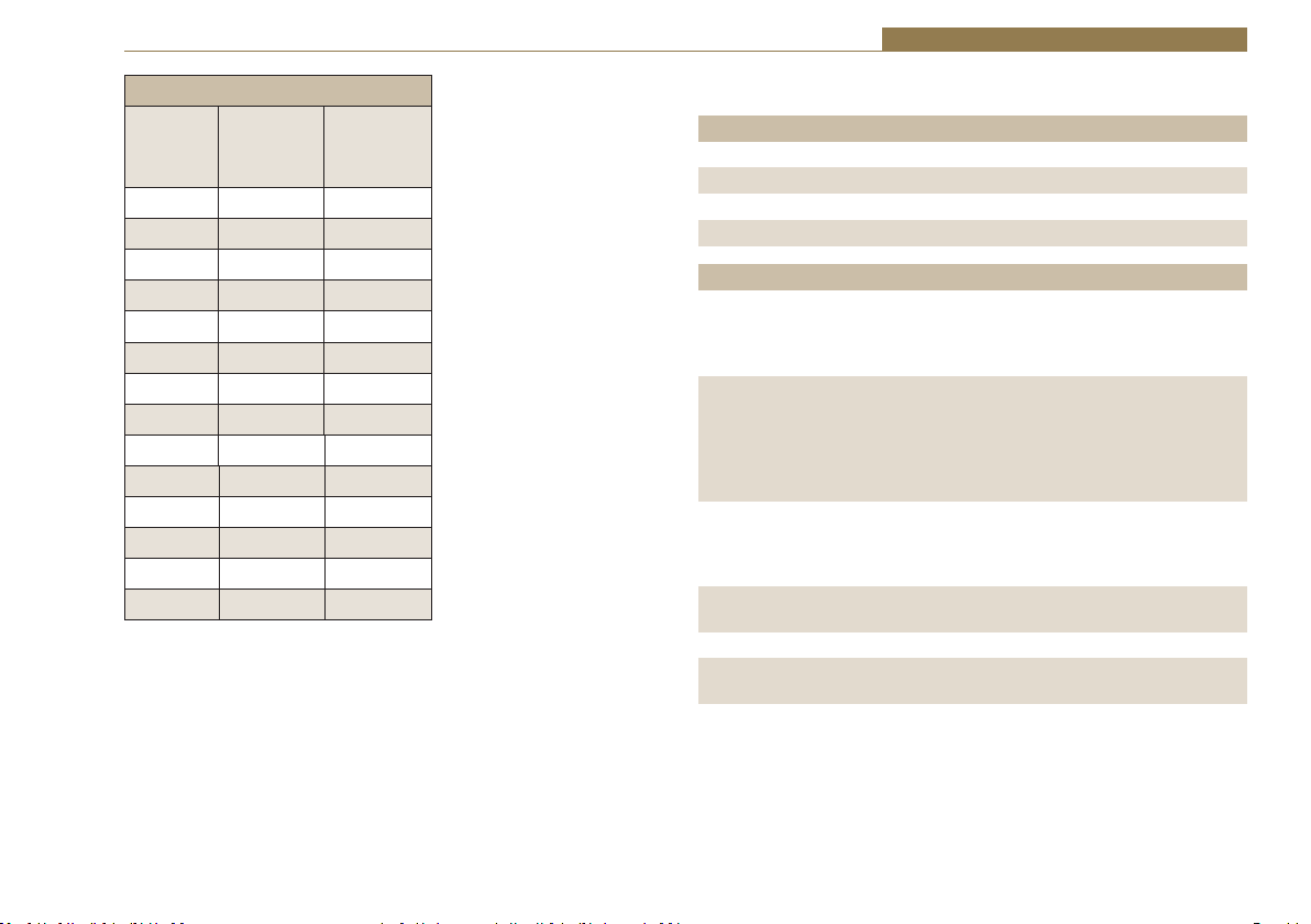
Frequencies and Sync Modes
Rotary Switch
Number
Mode Sample Frequency
(kHz)
0 Master 32
1 Master 44.1
2 Master 48
3 Master 64
4 Master 88.2
5 Master 96
6Auto32
7 Auto 44.1
8Auto48
9Auto64
A Auto 88.2
BAuto96
C Auto Lock -
D Slave -
Fig 1-6: RB-ADDA Frequency and Sync Rotary Switch
Test/Calibration Mode
For optimum performance of the RB-ADDA, the unit should be calibrated
when it has been powered up for approximately 10-15 minutes. The
circuitry and chipsets contained in the unit will warm up during this time
and the performance will deteriorate unless calibrated (the noise floor
and dynamic range will be 1-2dB down on their best). The calibration cycle
calibrates the gain and the zero reference of the A/D converter.
To calibrate the RB-ADDA, set the rotary FREQUENCIES AND SYNC MODES
switch to position “F”. The power LED on the front panel will flash quickly
for 2 – 3 seconds and will illuminate fully when the unit is calibrated. Once
calibration is complete, reset the rotary switch to the position that you
require.
5

1 Digital Audio Converters - RB- ADDA
Technical Specifications RB-ADDA
A/D Connections
Analogue Inputs: 2 x XLR 3 pin (balanced) (L & R)
2 x RCA phono (unbalanced) (L & R)
Digital Outputs: 1 x AES/EBU XLR 3 pin plug
1 x S/PDIF RCA phono socket
A/D Audio Specification
Maximum Input Level: +27dBu (balanced inputs)
Maximum Input Level: +17dBu (unbalanced inputs)
/ŶƉƵƚ/ŵƉĞĚĂŶĐĞ хϭϬŬɏďƌŝĚŐŝŶŐ;ďĂůĂŶĐĞĚŝŶƉƵƚƐͿ
/ŶƉƵƚ/ŵƉĞĚĂŶĐĞ хϮϬŬɏ;ƵŶďĂůĂŶĐĞĚŝŶƉƵƚƐͿ
Input Levels: Switchable +24dBu/+18dBu/+12dBu for FSD
Gain Range: Adjustable 3dB loss to 3dB gain (L and R adjust)
Signal to Noise: Better than –109dbFS (RMS A-weighted
at 24bit)
Dynamic Range: >110dB
Distortion and Noise: >96dB THD + N at 1kHz
D/A Connections
Digital Inputs: 1 x AES/EBU XLR 3 pin female
1 x S/PDIF RCA phono
Analogue Outputs: 2 x XLR 3 pin male (balanced) (L & R)
2 x RCA phono (unbalanced) (L & R)
D/A Audio Specification
Max Output Level: +24dBu (balanced outputs)
Max Output Level: +14dBu (unbalanced outputs)
KƵƚƉƵƚ/ŵƉĞĚĂŶĐĞ фϱϬɏ;ďĂůĂŶĐĞĚŽƵƚƉƵƚƐͿ
KƵƚƉƵƚ/ŵƉĞĚĂŶĐĞ фϳϱɏ;ƵŶďĂůĂŶĐĞĚŽƵƚƉƵƚƐͿ
Dynamic Range: >100dB
Gain Range: Selectable 12dBu, 18dBu or 24dBu output
level, ref FSD
Other Connections
Mains Input: Filtered IEC, 110-120V, or 220-240V switchable,
10W max
Fuse Rating: Anti-surge fuse 100mA 20 x 5mm (230VAC)
Anti-surge fuse 250mA 20 x 5mm (115VAC)
Operational Controls
Analogue Input Select: XLR or phono, via push-switch
Bit Depth: 16, 20 or 24 bits via DIP switch
Digital Output Select: AES/EBU or S/PDIF, via push-switch
Modes & Frequencies: 16 way rotary DIP switch
Digital Input Select: AES/EBU or S/PDIF, via push-switch
Channel Status Bits: Set to consumer or professional mode via
DIP switch
Equipment Type
RB-ADDA Combined A/D and D/A converter
Physical Specifications
Dimensions (Raw) 48cm (W) x 10.8cm (D) x 4.2cm (H) (1U)
19” (W) x 4.3” (D) x 1.7” (H) (1U)
Dimensions (Boxed) 58.5cm (W) x 22.5cm (D) x 7cm (H)
23” (W) x 8.9” (D) x 2.8” (H)
Weight Nett: 1.6kg Gross: 2.2kg
Nett: 3.5lbs Gross: 4.8lbs
6

Digital Audio Converters - RB-ADDA2 2
2 RB-ADDA2 Combined A/D and D/A Converter 24bit 192kHz
Introduction
Sync Button
and LEDs
Frequency Set
Button and LEDs
Bits Button
and LEDs
Reset
Button
Fig 2-1: RB-ADDA2 Front Panel
The RB-ADDA2 A/D and D/A converter is a 1U rackmount which produces an AES/EBU, S/PDIF or TOSlink
optical level digital audio output from a balanced XLR or
2
9
1
The RB-ADDA2 is a high performance, enhanced version of the RB-ADDA
providing the following additional features:
• It supports higher sample frequency rates up to and including 176.4kHz
and 192kHz.
• It has additional independent AES/EBU and Word Clock synchronising
inputs, so that the A/D and D/A sections can operate independently, with
the digital outputs synchronised to an external master reference clock.
• It has TOSlink optical digital audio input and output.
• It has front panel push-button switches for all the main settings. The
buttons are arranged in sets, where pressing the button advances the
current selection and LED indicator.
unbalanced phono stereo audio input. It also produces a
stereo balanced XLR or unbalanced phono output from an
incoming AES/EBU, S/PDIF or TOSlink optical digital input
signal.
A/D Source Select
Button and LEDs
CS Data Button
and LEDs
• A serial RS232 port is included so that the RB-ADDA2 settings can be
controlled remotely. The front panel LED indicators alter automatically
when using RS232 commands.
The A/D SOURCE push-button is used to select from either the balanced
or unbalanced stereo analogue inputs and this push-button also defines
the input level for full scale digits at one of +12dBFS, +18dBFS or
+24dBFS. These values can then be fine-tuned by using rear-panel pre-set
potentiometers which give another ±3dB of gain adjustment, allowing a
signal range from +9dBu to +27dBu. The RCA phono inputs have a further
10dB nominal gain incorporated to give a total signal range of -1dBu to
+17dBu for full-scale digits.
For the digital output, there are three push-button switches to select the
sample frequency, bit depth and status bit modes. The FREQUENCY button
allows selection of the master sample frequency from one of 32kHz,
44.1kHz, 48kHz, 88.2kHz, 96kHz, 176.4kHz or 192kHz. The BITS button sets
the output bit depth as one of 16, 20 or 24 bits, and the CS DATA button
defines the content of the channel status bits embedded within the digital
D/A Source Select
Button and LEDs
7

2 Digital Audio Converters - RB-ADDA2
audio stream. The channel status can be forced to either Professional
Mode (PRO), Consumer Mode (CON) or to follow the mode of the input
(FOLLOW).
The SYNC button is used to select the synchronisation input, from Word
Clock, AES/EBU or the D/A input, and also the synchronisation mode of the
digital output. The A/D section of the RB-ADDA2 operates in four selectable
modes:
Master Mode
In this mode the unit receives an analogue audio signal, which is digitised
and formatted for digital serial transmission (IEC958). The necessary
clock signals are generated internally from an on board master clock at
a selectable rate (32kHz, 44.1kHz, 48kHz, 88.2kHz, 96kHz, 176.4kHz or
192kHz).
Slave Mode
In this mode the unit is synchronised to an external source, using the digital
audio sync or D/A input signal from which the clock signals are stripped,
or to the TTL level Word Clock. The FREQUENCY LED will indicate the
synchronised sample frequency and if no sync is present, no output will be
generated.
Auto Mode
Here, the unit is synchronised to an external source, using the digital audio
sync or D/A input signal from which the clock signals are stripped, or to
the TTL level Word Clock. If no sync signal is present the unit runs from the
onboard master clock at a rate selected by the front panel control (32kHz,
44.1kHz, 48kHz, 88.2kHz, 96kHz, 176.4kHz or 192kHz).
Auto Lock Mode
This operates like the auto mode except that if no sync signal is present
the unit will run at the closest master clock rate to the last locked incoming
signal. The FREQUENCY LED will indicate the synchronised sample
frequency.
When operating in sync modes, the SYNC button flashes whenever the unit
is not synchronised to the incoming digital signal.
The D/A section has one SOURCE push-button which is used to select the
digital input source from AES/EBU, S/PDIF or TOSlink optical and which
also sets the analogue output level to be generated for full scale digits,
from either +12dBFS, +18dBFS or +24dBFS. The RCA phono outputs have a
further 10dB nominal attenuation to reduce the signal to that expected by
consumer equipment. There are factory-set internal level controls for fine
tuning the analogue output gain adjustment. If no digital audio source is
present, the D/A SOURCE button flashes.
The RB-ADDA2 automatically decodes 50/15μs emphasis if this is indicated
by certain channel status bits in the incoming digital audio data. In both A/D
and D/A sections, audio is sent to all of the outputs simultaneously. A red
LED indicates when power to the RB-ADDA2 is on.
8

System Block Diagram
Digital Audio Converters - RB-ADDA2 2
L
R
L
R
Digital Source
Select
AES
Rec
Rec
Gain
Gain
Analogue
Input Select
Digital Input
Optical
AES/EBU
S/PDIF
Sync Input
AES/EBU
Word
Clock
Professional
Balanced
Analogue
Input
Consumer
Unbalanced
Fig 2-2: RB-ADDA2 System Block Diagram
Front Panel Controls & Indicators
The LED on the front panel is normally red to indicate that power is present
on the unit.
SYNC Button & LEDs
This button will select one of the 4
operating modes for the RB-ADDA2
Analogue to Digital conversion. 3 modes
use an external sync and this button is
also used to select the external sync
source that generates the sampling frequency used. The Mode button will
flash when the external sync signal selected is not present.
A/D SOURCE Select Button & LEDs
This button will select between the balanced and unbalanced analogue
audio inputs for the RB-ADDA2. Analogue to Digital conversion. The signal
Fig 2-3: SYNC Button & LEDs
AES
Rec
ADC
DAC
Master
Clock
Generator
AES
Transmitter
level corresponding to full-scale digits
can be set to +12, +18 or +24dBu.
FREQUENCY Set Button & LEDs
When the button is not illuminated it
will select the internal master frequency
that is used in Master Mode and in Auto
Mode when no sync signal is present.
At other times, when the button is
illuminated, the LEDs will show the actual
sampling frequency of the incoming sync
source. To view the Master Frequency
press the button once to enter the
setting mode. Any further button presses
will advance the set frequency.
L
Professional
Balanced
R
Analogue
Output
L
Consumer
Unbalanced
R
Frequency
Select
Digital
Output
AES/EBU
S/PDIF
Optical
Fig 2-4: A/D SOURCE Select
Button & LEDs
Fig 2-5: FREQUENCY Set
Button & LEDs
9

2 Digital Audio Converters - RB-ADDA2
CS DATA Button & LEDs
This button will select the type of channel status bits to be embedded in the
digital audio output – either professional or consumer. The channel status
type can be set directly or can follow the digital audio input source.
BITS Button & LEDs
This button sets the bit depth of the RB-ADDA2 Analogue to Digital
conversion to 16, 20 or 14 bits. The bit depth is reflected in the appropriate
channel status bits in the digital output stream.
D/A SOURCE Select Button & LEDs
This button will select the digital audio input source for the RB-ADDA2
Digital to Analogue conversion and will also set the level of the output
signal corresponding to full-scale digits to +12, +18 or +24dBu. The D/A
SOURCE select button will flash if the digital audio source selected is not
present.
Reset Button
In the unlikely event that the RB-ADDA2 unit fails to respond, press the
reset button to reboot the unit (see Fig 2-1 for location).
Fig 2-6: CS DATA Button & LEDs
Fig 2-7: BITS Button & LEDs
Fig 2-8: D/A SOURCE Select Button & LEDs
Rear Panel Connections and Operation
RCA Phono Inputs XLR Analogue Outputs
XLR Analogue Inputs
Input Level Adjustment
Fig 2-9: RB-ADDA2 Rear Panel
10
RCA Phono Outputs AES Digital
Output
SPDIF
Output
Optical
Output
SPDIF
Input
Optical
Input
AES Digital
Input
AES
Sync Input
Word Clo ck
Sync Input
RS232
Fuse
IEC Mains
Input

Digital Audio Converters - RB-ADDA2 2
RB-ADDA2 Inputs
XLR Analogue Inputs (Left and Right)
The XLR 3 pin sockets used for the left and right channel inputs are
ĞůĞĐƚƌŽŶŝĐĂůůLJďĂůĂŶĐĞĚĂŶĚŚĂǀĞĂŶŝŵƉĞĚĂŶĐĞŽĨŐƌĞĂƚĞƌƚŚĂŶϭϬŬɏ
bridging. Each XLR has the following connections:
Pin 1: Screen.
Pin 2: Phase.
Pin 3: Non-phase.
RCA Phono Inputs (Left and Right)
The two left and right RCA inputs are unbalanced and have an impedance of
ŐƌĞĂƚĞƌƚŚĂŶϮϬŬɏ
Input Level Adjustment
The input gain is set for both left and right channels by using the A/D
SOURCE Select Button (Fig 2-4). Pre-set potentiometers, accessible on the
rear panel, give a further ± 3dBu to give a total signal range of +9dBu to
+27dBu for full-scale digits.
The RCA Phono Inputs have a further 10dBu nominal gain incorporated to
give a total signal range of -1dBu to +17dBu for full-scale digits.
AES/EBU Input
dŚĞĚŝŐŝƚĂůŝŶƉƵƚy>ZϯƉŝŶƐŽĐŬĞƚŚĂƐĂŶŝŵƉĞĚĂŶĐĞŽĨϭϭϬɏ/ƚŚĂƐƚŚĞ
following connections:
Pin 1: Screen
Pin 2: Phase
Pin 3: Non-phase
The signals on this connector should meet the IEC 60968 specification
S/PDIF Input
dŚĞ^W/&ĚŝŐŝƚĂůƉŚŽŶŽŝŶƉƵƚŚĂǀĞĂŶŝŵƉĞĚĂŶĐĞŽĨϳϱɏ
Optical Input
The digital audio optical input meets the TOSLink specification used by most
professional & consumer equipment.
AES/EBU Sync Input
dŚĞĚŝŐŝƚĂůŝŶƉƵƚy>ZϯƉŝŶƐŽĐŬĞƚŚĂƐĂŶŝŵƉĞĚĂŶĐĞŽĨϭϭϬɏ/ƚŚĂƐƚŚĞ
following connections:
Pin 1: Screen
Pin 2: Phase
Pin 3: Non-phase
The signals on this connector should meet the IEC 60968 specification.
Word Clock Input
The Word Clock input is designed to receive a distributed clock running
at the actual sampling frequency. The signal can be differential, or single
ended, TTL level.
RB-ADDA2 Outputs
Analogue Outputs (Left and Right)
The XLR 3 pin output plug connectors are electronically balanced with an
ŽƵƚƉƵƚŝŵƉĞĚĂŶĐĞŽĨůĞƐƐƚŚĂŶϱϬɏdŚĞLJŚĂǀĞƚŚĞĨŽůůŽǁŝŶŐĐŽŶŶĞĐƚŝŽŶƐ
Pin 1: Screen.
Pin 2: Phase.
Pin 3: Non-phase.
RCA Phono Outputs (Left and Right)
These RCA (phono) outputs are unbalanced and have an output impedance
ŽĨůĞƐƐƚŚĂŶϳϱɏ
Output Level Adjustment
The output gain can be individually adjusted for left and right channels
through the front panel by the D/A SOURCE Select button (Fig 2-8). Each
output gain can be set for a signal of full-scale digits in the digital domain
to give +12, +18 or +24dBu output on the XLR connectors. The RCA phono
outputs have a further 10dBu nominal attenuation incorporated.
AES/EBU Output
dŚĞĚŝŐŝƚĂůŽƵƚƉƵƚy>ZϯƉŝŶƐŽĐŬĞƚŚĂƐĂŶŝŵƉĞĚĂŶĐĞŽĨϭϭϬɏ/ƚŚĂƐƚŚĞ
following connections:
11

2 Digital Audio Converters - RB-ADDA2
Pin 1: Screen
Pin 2: Phase
Pin 3: Non-phase
The signals on this connector will comply with the IEC 60968 specification
S/PDIF Output
dŚĞĚŝŐŝƚĂůŽƵƚƉƵƚ^W/&ƉŚŽŶŽŽƵƚƉƵƚŚĂƐĂŶŝŵƉĞĚĂŶĐĞŽĨϳϱɏ
Optical Output
The digital audio optical output meets the TOSLink specification used by
most professional & consumer equipment.
Serial Port Control
The Serial Port allows the RB-ADDA2 to be controlled and updated from a
PC via a pin-to-pin serial cable, using the Sonifex Serial Control Interface
(SCI) software. This software is available as a free download from the
Sonifex website at www.sonifex.co.uk/sci.
Default Settings for the Serial Port
Baud Rate: 19200
Data Bits: 8
Stop Bits: 1
Parity: Even
Handshaking: XON/XOFF
Serial Interface Commands and Responses
Most of the commands follow the same structure: a 3 letter command
f
ollowed by a colon, followed by a parameter (if any) and terminated by
Carriage Return with optional Line Feed. A Line Feed character may be sent
but it will be ignored by the RB-ADDA2. Commands are not case sensitive
and all parameters are in hex.
Responses are CR & LF terminated.
After the RB-ADDA2 has been powered-up, an initialisation string is sent
“Initialising ADDA2”.
Following are the commands and the expected responses:
Command Description Response
ADB:nn - Set ADC Bit Size - ACK:
nn=00 - 16 Bits
nn=01 - 20 Bits
nn=02 - 24 Bits
ADC:nn - Set ADC Channel Status Type - ACK:
nn=00 - Send Consumer CS Data
nn=01 - Follow Sync Input (or use last set)
nn=02 - Send Professional CS Data
ADF:nn - Set ADC Channel Status Type - ACK:
nn=00 - Select 32kHz Master Clock Sample Rate
nn=01 - Select 44kHz Master Clock Sample Rate
nn=02 - Select 48kHz Master Clock Sample Rate
nn=03 - Select 88kHz Master Clock Sample Rate
nn=04 - Select 96kHz Master Clock Sample Rate
nn=05 - Select 176kHz Master Clock Sample Rate
nn=06 - Select 192kHz Master Clock Sample Rate
ADM:nn - Set ADC Mode & Select Sync Source - ACK:
nn=00 - Master Mode
nn=04 - Auto Mode
nn=08 - Auto Lock Mode
nn=10 - Slave Mode
For last three modes add
nn=01 - Select External AES Sync input as sync source
nn=02 - Select DA Stage input as sync source
nn=03 - Select Word Clock input as sync source
ADS:nn - Set ADC Source & Full Scale Input Level - ACK:
nn=00 - Select Balanced XLR Inputs
nn=04 - Select Unbalanced Phono Inputs
And add
12

Digital Audio Converters - RB-ADDA2 2
nn=01 - +12dBu represents Full Scale Digits (+2 for
unbalanced)
nn=02 - +18dBu represents Full Scale Digits (+8 for
unbalanced)
nn=03 - +24dBu represents Full Scale Digits (+14
for unbalanced)
Bnn: - Baud Rate - ACK: (at old rate)
nn=11 (115200)
nn=57 (57600)
nn=38 (38400)
nn=19 (19200)
nn=96 (9600)
DAS:nn - Set DAC Source & Full Scale Output Level - ACK:
nn=04 - Select AES Digital Audio Input
nn=08 - Select SPDIF Digital Audio Input
nn=10 - Select Optical Digital Audio Input
And add nn=01 - Full Scale Digits Sends +12dBu Out (+2 for
unbalanced)
nn=02 - Full Scale Digits Sends +18dBu Out (+8 for
unbalanced)
nn=03 - Full Scale Digits Sends +24dBu Out (+14 for
unbalanced)
DWN: - Download new code -OK: then erasing message
Then send S-records followed by
S-record terminator to
force programming of flash memory
and reboot
FPS: - Request Front Panel Settings - FPS:aa_bb_cc_dd_ee_ff
Where aa = value from ADC Mode as ADM: above
bb = value from ADC Source as ADS: above
cc = value from ADC Frequency as ADF: above
dd = value from ADC Bits as ADB: above
ee = value from ADC CS Data Select as ADC: above
ff = value from DAC Source as DAS: above
LOC: - Lock Front Panel - ACK:
MEM: - Memory Dump - Memory, then 10 lines
Madd:data
Where add is memory address starting at 060(hex)
and data is 16 bytes of data, each byte shown as 2 hex
digits
MFn: - Limit Front Panel Frequency Selection - ACK:
Where n=0 for No Limit
n=1 for 48kHz Limit &
n=2 for 96kHz Limit
REG: - Register Dump
- Registers, then 4 lines of 8 x Rrr:dd
Where rr is register number and dd is value shown as
2 hex digits
SER: - Serial Number request - SER:012345
SRQ: - Status Request - STA:aa_dd_ss
Where aa = ADC Status
dd = DAC Status
ss = Internal Status
STK: - Stack Dump - STK: aaaa, then 6 lines Sadd:data
Where aaaa= current Stack Pointer,
add is memory address starting at 0800(hex)
and data is 16 bytes of data, each byte shown as
2 hex digits
UNL: - Unlock Front Panel - ACK:
UID: - Unit ID Request - UID:ADDA2
VER: - Firmware Version Request - VER:1.23 or BOOT:1.23
Error messages
The following error messages can be returned for illegal commands
Err:01 - return if Command Not Found
Err:02 - return if Missing Parameter
Err:04 - return if Parameter out of range
13

2 Digital Audio Converters - RB-ADDA2
Upgrading Firmware
Occasionally, it may be necessary to upgrade the firmware on the RBADDA2 to add new functionality and fix software bugs. New firmware
updates will be made available from time to time on the Sonifex website.
Visit www.sonifex.co.uk for details.
The firmware is upgraded using the Serial Control Interface - SCI. This PC
software downloads the new firmware and initiates the upgrade process. To
upgrade the firmware, select the required firmware file in the SCI upgrade
firmware section. The RB-ADDA2 will automatically reboot and enter the
bootstrap mode prior to the transfer of the firmware file. The SCI software
downloads the firmware to internal memory, and then erases the current
firmware before programming the update. When the firmware is complete,
the unit reboots with the new firmware.
Please note: Firmware files can take several minutes to transfer to the RBADDA2 at lower baud rates. To speed up the process, select a higher baud
rate prior to transferring the new firmware.
Technical Specifications RB-ADDA2
A/D Connections
Analogue Inputs: 2 x XLR 3 pin (balanced) (L & R)
2 x RCA phono (unbalanced) (L & R)
Digital Outputs: 1 x AES/EBU XLR 3 pin plug
1 x S/PDIF RCA phono socket
1 x TOSLink optical output
Sync Inputs: 1 x AES/EBU XLR 3 pin female
1 x Word Clock BNC
A/D Audio Specification
Maximum Input Level: +27dBu (balanced inputs)
Maximum Input Level: +17dBu (unbalanced inputs)
/ŶƉƵƚ/ŵƉĞĚĂŶĐĞ хϭϬŬɏďƌŝĚŐŝŶŐ;ďĂůĂŶĐĞĚŝŶƉƵƚƐͿ
/ŶƉƵƚ/ŵƉĞĚĂŶĐĞ хϮϬŬɏ;ƵŶďĂůĂŶĐĞĚŝŶƉƵƚƐͿ
Input Levels: Switchable +24dBu/+18dBu/+12dBu for FSD
(on bal inputs)
Gain Range: Adjustable 3dB loss to 3dB gain (L and R adjust)
Signal to Noise: Better than –113dbFS (RMS A-weighted
at 24bit)*
Dynamic Range: Better than -110dB*
Distortion and Noise: Better than -100dB THD + N at 1kHz*
Cross-talk: Better than -112dB (20Hz to 20kHz)*
* Measured using balanced inputs
A/D Operational Controls
Analogue Input Source: Balanced XLRs or unbalanced phonos, via
A/D SOURCE push-button
Analogue Input Level
for FSD: +12dBFS, +18dBFS or +24dBFS, via A/D
SOURCE push-button
Analogue Input Level: +9dBu to +27dBu via rear-panel
14
Digital Audio Converters - RB-ADDA2 2
Adjust: +3dB via pre-set pots
Sample Frequency Rates: 32kHz, 44.1kHz, 48kHz, 88.2kHz, 96kHz,
176.4kHz or 192kHz, via FREQUENCY
push-button
Bit Depth: 16, 20 or 24 bits, via BITS push-button
Channel Status Bits: Consumer mode, professional mode or follow
input, via CS DATA push-button
Sync Input Select: AES/EBU, Word Clock or D/A input, via SYNC
push-button
Sync Mode Select: Master, slave, auto, auto lock, via SYNC
push-button
D/A Connections
Digital Inputs: 1 x AES/EBU XLR 3 pin female
1 x S/PDIF RCA phono
1 x TOSLink optical input
Analogue Outputs: 2 x XLR 3 pin male (balanced) (L & R)
2 x RCA phono (unbalanced) (L & R)
D/A Audio Specification
Max Output Level: +24dBu (balanced outputs)
Max Output Level: +14dBu (unbalanced outputs)
KƵƚƉƵƚ/ŵƉĞĚĂŶĐĞ фϱϬɏ;ďĂůĂŶĐĞĚŽƵƚƉƵƚƐͿ
KƵƚƉƵƚ/ŵƉĞĚĂŶĐĞ фϳϱɏ;ƵŶďĂůĂŶĐĞĚŽƵƚƉƵƚƐͿ
Gain Range: Selectable 12dBu, 18dBu or 24dBu output level,
ref FSD (on balanced inputs)
Signal to Noise: Better than -106dB (RMS A-weighted at 24 bit)*
Dynamic Range: Better than-100dB*
Distortion and Noise: Better than -85dB THD +N at 1kHz*
Cross-talk: Better than -112dB (20Hz to 20kHz)*
* Measured at balanced outputs
Other Connections
Mains Input: Universal filtered IEC, continuously rated
85-264VAC @47-63Hz, max 10W
Fuse Rating: Anti-surge fuse 1A 20 x 5mm
Serial Port: RS232 9 Pin D-type socket
D/A Operational Controls
Digital Input Select: AES/EBU, S/PDIF or TOSlink optical, via D/A
SOURCE push-button
Analogue Output Selectable +12dBu, +18dBu or +24dBu
output level, ref
Level for FSD: FSD, via D/A SOURCE push-button
Equipment Type
RB-ADDA2 Combined A/D and D/A converter, 24 bit 192kHz
Physical Specifications
Dimensions (Raw) 48cm (W) x 15.8cm (D*) x 4.2cm (H) (1U)
19” (W) x 6.2” (D*) x 1.7” (H) (1U)
Dimensions (Boxed) 59cm (W) x 27.4cm (D*) x 10.8cm (H)
23.2” (W) x 10.8” (D*) x 4.3” (H)
Weight Nett: 1.6kg Gross: 2.3kg
Nett: 3.5lbs Gross: 5lbs
* Note that this product is deeper than standard Redboxes.
15

3 Digital Audio Converters - RB-SC1
3 RB-SC1 Sample Rate Converter
Introduction
Fig 3-1: RB-SC1 Front Panel
The RB-SC1 Sample Rate Converter standardises the sample rate of a
digital audio signal to one of 32kHz, 44.1kHz, 48kHz or 96kHz, or to a
synchronising input, selectable from AES/EBU, S/PDIF or TTL Word Clock.
System Block Diagram
If synchronising to an external signal there are several modes causing
different actions in case of loss of the synchronising signal.
There are also switches available to define the content of the channel status
bits embedded within the digital audio stream.
Digital
Input
AES/EBU
SPDIF
Digital Sync
Input
AES/EBU
SPDIF
Word
Clock
Fig 3-2: RB-SC1 System Block Diagram
Digital
Source
Select
Digital Sync
Select
16
AES
Receiver
Clock
AES
Receiver
Converter
Conversion
Clock
Sample
Rate
AES
Transmitter
Frequency
Select
Master
Clock
Generator
Digital Send
Select
Digital
Output
AES/EBU
SPDIF

Digital Audio Converters - RB-SC1 3
Front Panel Indicators
Front Panel LED
The LED on the front panel is normally red to indicate that power is present
on the unit. However, it also has a secondary role to indicate the status of
the digital inputs
Fast flashing between red and amber – indicates a loss of digital input
signal.
Slow flashing between red and amber - when not in master mode this
indicates the absence of a synchronising input.
Rear Panel Connections and Operation
AES/EBU
Audio
Input
Status
Select Switches
Digital Input
Select Button
Fig 3-3: RB-SC1 Rear Panel
Inputs and Outputs
AES/EBU Inputs
The digital source and digital sync XLR 3 pin sockets both have an
ŝŵƉĞĚĂŶĐĞŽĨϭϭϬɏdŚĞLJŚĂǀĞƚŚĞĨŽůůŽǁŝŶŐĐŽŶŶĞĐƚŝŽŶƐ
S/PDIF
Input
S/PDIF
Output
AES/EBU
Audio
Output
Digital Output
Select Button
AES/EBU
Input
Digital Sync Input
S/PDIF
Sync
Select Button
Sync
Input
Frequency and
Sync Mode
Rotary Switch
Word-Clock Sync Input
Pin 1: Screen
Pin 2: Phase
Pin 3: Non-phase
The signals on these connectors should meet the IEC
60968 specification
S/PDIF Inputs
The digital source and digital sync S/PDIF phono inputs
ďŽƚŚŚĂǀĞĂŶŝŵƉĞĚĂŶĐĞŽĨϳϱɏ
Word Clock Input
dŚĞEdd>ǁŽƌĚĐůŽĐŬŝŶƉƵƚŚĂƐĂŶŝŵƉĞĚĂŶĐĞŽĨϱϬɏ
AES/EBU Output
The digital output XLR 3 pin socket has an impedance of
ϭϭϬɏ/ƚŚĂƐƚŚĞĨŽůůŽǁŝŶŐĐŽŶŶĞĐƚŝŽŶƐ
Pin 1: Screen
Pin 2: Phase
Pin 3: Non-phase
The signals on this connector will comply with the IEC
60968 specification
S/PDIF Output
The digital output S/PDIF phono output has an impedance
ŽĨϳϱɏ
Rear Panel Controls
Status Select Switches
These switches are used to determine the content of the
channel status bits embedded within the digital audio
stream (switches 1 and 2) and to select the source for the
digital sync signal from either digital audio input or TTL
word clock (switch 3).
17

3 Digital Audio Converters - RB-SC1
The channel status bits will be forced to Professional Mode for the highest 3
sample rates as they are not supported by consumer mode. For the lowest
three rate these status bits can be either set to follow the input signal type
(switch 1 off) or can be forced to either professional or consumer mode
(switch 1 on and switch 2 either off or on). These settings are summarised
in Fig 3-4 and are also on top of the unit.
Status Select Switch Settings
1 On Force channel status type to...
1 Off Follow input
2 On Professional output
2 Off Consumer output
3 On Digital sync
3OffWord-clock sync
Fig 3-4: RB-SC1 Status Switches
Digital Input Select Buttons
These buttons are used to switch the digital connection between the
AES/EBU XLR connector (button out) and the S/PDIF phono connector
(button in) for the digital source, the digital sync input and the digital
output
Frequency and Sync Mode Rotary Switch
This rotary switch is used to select the synchronisation mode and to
select the frequency of the digital output when using the on-board clock
generator. There are 4 modes of operation :- Master mode, Auto Sync
Mode, Auto Lock Sync Mode & Slave Mode.
In Master sync mode, switch positions 0 – 5, the digital output sample rate
is simply set by, and locked to, the internal on-board clock generator. No
sync signal is used or required.
In Auto sync mode, switch positions 6– B, the digital output sample rate
follows the sync input. When the sync signal is not present the output
sample rate will be set by, and locked to, the internal on-board clock
generator at a frequency determined by the switch position.
In Auto-Lock sync mode, switch position C, no output will be generated
until lock is achieved with a sync signal. The digital output sample rate now
follows the sync input. If the sync signal is removed then the output sample
rate will be set by, and locked to, the internal on-board clock generator at
the closest frequency available to the previous sync input.
In Slave sync mode, switch position D, the digital output sample rate follows
the sync input. When the sync signal is not present the digital output is
turned off.
Fig 3-5, also printed on the top of the unit, summarises the rotary switch
settings and shows the sample rate generated by the internal clock
generator in master and auto sync modes.
18
Digital Audio Converters - RB-SC1 3
Frequencies and Sync Modes
Rotary
Switch
Number
0 Master 32
1 Master 44.1
2 Master 48
3 Master 96
4 Master 96
5 Master 96
6Auto32
7 Auto 44.1
8Auto48
9Auto96
AAuto96
BAuto96
C Auto Lock -
D Slave -
Fig 3-5: RB-SC1 Frequency and Sync Rotary Switch Settings
Mode Sample
Frequency
(kHz)
Technical Specifications RB-SC1
Audio Specification
Dynamic Range: 120dB
Distortion & Noise: -114dB THD + N at 1kHz, ref 0dB FS
Sample Freq Range: 30kHz – 100kHz
Bit Depth: Up to and including 24 bits.
Connections and Controls
Audio Inputs: 1 x AES/EBU XLR 3 pin female
1 x S/PDIF RCA phono female
(Input button select between AES/EBU and
S PDIF)
Sync Inputs: 1 x AES/EBU XLR 3 pin female
1 x S/PDIF RCA phono female
1 x TTL BNC female
(Input button select between AES/EBU and
S/PDIF, and DIP switch select between TTL and
either of the other two)
Outputs: 1 x AES/EBU XLR 3 pin male
1 x S/PDIF RCA phono female
(Output button select between AES/EBU
and S/PDIF);
Mains Input: Filtered IEC, continuously rated 85-264VAC
@47-63Hz, max 10W
Fuse Rating: Anti-surge fuse 1A 20 x 5mm
Operational Modes: Master mode, auto sync mode, auto lock mode
and slave mode, set via rotary switch
Status bits: Forced to consumer mode, professional mode,
or set to follow input
19

3 Digital Audio Converters - RB-SC1
Equipment Type
RB-SC1 Sample rate converter
Physical Specifications
Dimensions (Raw) 28cm (W) x 10.8cm (D) x 4.2cm (H) (1U)
11” (W) x 4.3” (D) x 1.7” (H) (1U)
Dimensions (Boxed) 36cm (W) x 20.5cm (D) x 6cm (H)
14.2” (W) x 8” (D) x 2.4” (H)
Weight Nett: 1.0kg Gross: 1.4kg
Nett: 2.2lbs Gross: 3.1lbs
20

4 RB-SC2 Dual Sample Rate Converter
Introduction
Frequency Button and LEDs Input 1 Button and LEDs Sync Button and LEDs
CS Data Button and LEDsReset Button Input 2 Button and LEDs
Fig 4-1: RB-SC2 Front Panel
The RB-SC2 sample rate converter is a 1U rack-mount
which produces AES/EBU, S/PDIF and TOSlink optical level
digital audio outputs from a balanced AES/EBU, S/PDIF and
2
9
1
The RB-SC2 is a high performance, enhanced version of the RB-SC1
providing the following additional features:
• It supports higher sample frequency rates up to and including 176.4kHz
and 192kHz.
• It has 2 independent sample rate converter circuits that use a common
clock source to set the output sample rate.
• It has 2 optional video synchronising boards. These set the output
sample rate to 48kHz that is synchronised to either an analogue video
signal or SDI digital video signal (HD or SD).
• A special X-Lock mode allows the unit to function as a full bi-directional
sample rate converter.
• It has TOSlink optical digital audio inputs and outputs.
TOSlink optical level digital audio inputs. The sample rate of
the outputs can be set by an internal clock or from various
external synchronizer sources.
Digital Audio Converters - RB-SC2 4
• It has front panel push-button switches for all the main settings. The
buttons are arranged in sets, where pressing the button advances the
current selection and
LED indicator.
• A serial RS232 port is included so that the RB-SC2 settings can be
controlled remotely. The front panel LED indicators alter automatically
when using RS232 commands.
For the digital outputs, there are three push-button switches to select the
sample frequency (FREQUENCY), channel status bit type (CSDATA), and sync
source and mode of operation (SYNC).
The FREQUENCY button allows selection of the master sample frequency
from one of 32kHz, 44.1kHz, 48kHz, 88.2kHz, 96kHz, 176.4kHz or 192kHz.
The CS DATA button defines the content of the channel status bits
embedded within the digital audio stream, and can be forced to either
Professional Mode (PRO), Consumer Mode (CON) or to follow the mode of
the input (FOLLOW).
The SYNC button is used to select the synchronisation input, from the AES/
EBU sync input, the Wordclock input or, for X-Lock, the other digital input.
21

4 Digital Audio Converters - RB-SC2
The X-Lock synchronisation allows the unit to act as a bi-directional sample
rate converter with the output of sample rate converter 1 syncing the input
of sample rate converter 2 and vice versa so that they follow each other.
The application for the X-Lock mode is so that the RB-SC2 can be inserted
between 2 digital devices which run at different sample rates, such as a PC
Slave Mode
In this mode the unit is synchronised to an external source, using the
digital audio sync, or to the TTL level Word Clock. The FREQUENCY LED will
indicate the synchronised sample frequency and if no sync is present, no
output will be generated.
recorder and a digital player. Using the RB-SC2 in X-Lock mode ensures that
the 2 devices remain synchronised at all times regardless of the sample rate
of the 2 devices.
Auto Mode
Here, the unit is synchronised to an external source, using the digital audio
sync, or to the TTL level Word Clock. If no sync signal is present the unit
The SYNC button will also select the operating mode of the unit as
described below. If an optional video sync board is fitted then 2 sync LEDs
runs from the onboard master clock at a rate selected by the front panel
control (32kHz, 44.1kHz, 48kHz, 88.2kHz, 96kHz, 176.4kHz or 192kHz).
light together to show the active video sync.
Auto Lock Mode
Master Mode
In this mode the unit receives a digital audio signal, which is passed to
the sample rate converter and then re-formatted for the digital serial
transmitter (IEC958). The sample rate converter clock signal is generated
This operates like the auto mode except that if no sync signal is present
the unit will run at the closest master clock rate to the last locked incoming
signal. The FREQUENCY LED will indicate the synchronised sample
frequency.
internally from an on board master clock at a selectable rate (32kHz,
44.1kHz, 48kHz, 88.2kHz, 96kHz, 176.4kHz or 192kHz).
When operating in sync modes, the SYNC button flashes whenever the unit
is not synchronised to the incoming sync signal.
System 1 RB-SC2 System 2
X-Lock Sync Mode
RX TXSRC
Sample
Rate 1
Clock
Recovery
Clock
Sync
Clock
Sync
Sample
Rate 2
Fig 4-2: RB-SC2 X-Lock Sync Mode
22
Clock
Recovery
RXTX SRC

Digital Audio Converters - RB-SC2 4
There are 2 further push-button switches (INPUT1 & INPUT2) that are used
to select the input connector used for each of the 2 sample rate converter
circuits. These switches select between AES/EBU, S/PDIF and TOSLink
optical connectors.
A red LED indicates when power to the RB-SC2 is on.
Installing the Optional Video Sync Boards
There are 2 optional video sync boards which can be used to synchronise
the outputs of the RB-SC2 to a 48kHz sample rate:
RB-SYA - The Analogue video sync board will accept a composite signal of
SC (525), PAL (625) & SECAM (625) signals covered by SMPTE-170-M
NT
(NTSC) and ITU-R BT.470-6 (PAL & SECAM).
RB-SYD - The Digital video sync board will accept 270Mbps SD-SDI and HD-
SDI signals c
overed by SMPTE-259-M-C (SD) and SMPTE-292M (HD).
Opening the RB-SC2
Warning : The power must be switched off at the supply or the power lead
must be disconnected before attempting to open the unit. Removal of the
cover can expose dangerous voltages.
Sync Card
Pillar Mount
PL7
S/PDIF &
OPTICAL
DIGITAL
OUTPUT 2
S/PDIF &
OPTICAL
DIGITAL
INPUT 2
AES/EBU
DIGITAL
OUTPUT 2
AES/EBU
DIGITAL
INPUT 2
20 Way Pin
Connector
PL3
AES/EBU
SYNC INPUT
PL1PL13PL14PL16PL15
PL2
Sync Card
Pillar Mount
SW1
SONIFEX
Wordclock
Front
Panel
Reset
RB-VIDEOSUB-01
JP1
PL8 RS232
1. Remove the 4 screws in the corners of the rear panel.
2. Remove the 4 screws on the top and bottom panels which hold the rear
panel in place (2 on the top and 2 on the bottom).
3. Remove the screw on the front panel underneath the CS DATA button.
4. Slide the rear panel and main PCB backwards out of the metal chassis
giving you internal access.
5. Remove the rubber grommet/bung on the rear panel which covers the
hole for the video sync connector.
6. Remove the 2 screws from the bottom of the sync card pillars and,
making sure to keep the plastic washers in place at the bottom of the
pillars, fit the 20 way pin header into the 20 way connector on the RBSC2 motherboard.
7. Underneath the board , insert the 2 screws to fix the board in place. To
put the unit back together, slide the PCB back into the chassis and refit
the screws in reverse order.
The RB-SC2 will auto-sense the video cards on powering up and the
relevant option will be avaiable using the SYNC button (see page 25).
Follow these instructions to fit either of the sync boards.
Fuse
Rating
Lamp
F1
PL17
Sync Card
Pillar Mount
20 Way Pin
Header
PL2
PL1
Sync Card
Pillar Mount
SONIFEX
RB-VIDEOSUB-01
Fig 4-3: RB-SC2 Optional Video Sync Installation
23

4 Digital Audio Converters - RB-SC2
AES/EBU
Optical
Digital Source
Select
S/PDIF
Conversion
Clock Select
X-Lock
Mode
Sample
Rate
Converter
AES
Transmitter
Master
Clock
Generator
AES
Receiver
Word Clock
Receiver
Video Clock
Receiver
Digital Input 1
AES/EBU
Optical
S/PDIF
Digital Output 1
AES/EBU
Optical
Digital Source
Select
S/PDIF
AES
Receiver
AES
Receiver
Sample
Rate
Converter
AES
Transmitter
Digital Input 2
AES/EBU
Optical
S/PDIF
Digital Output 2
Word Clock
AES/EBU
Frequency
Select
Video Input
Sync Input
Option Analogue
Or Digital
System Block Diagram
Fig 4-4: RB-SC2 System Block Diagram
24

Front Panel Controls & Indicators
The LED on the front panel is normally red to indicate that power is present
on the unit.
FREQUENCY Set Button & LEDs
When the button is not illuminated it will
select the internal master frequency that
is used in Master Mode and in Auto Mode
when no sync signal is present. At other
times, when the button is illuminated, the
LEDs will show the actual sampling frequency
of the incoming sync source. To view the
Master Frequency press the button once to
enter the setting mode. Any further button
presses will advance the set frequency.
CS DATA Button & LEDs
This button will select the type of channel
status bits to be embedded in the digital
audio output – either professional or
consumer. The channel status type can be set
directly or can follow the digital audio input
source.
INPUT1 & INPUT2 Source Select Button
& LEDs
This button will select between the balanced
AES/EBU, unbalanced S/PDIF and optical
digital audio inputs for the RB-SC2 sample
rate conversion.
The input buttons will flash when no suitable
source is available on the selected connector.
44.1kHz
32kHz
Fig 4-5: FREQUENCY Set Button & LEDs
88.2kHz
48kHz
FREQUENCY
CON
Fig 4-6: CS DATA Button & LEDs
AES
AES
Fig 4-7: INPUT 1 & INPUT2
Source Select Button & LEDs
96kHz
176.4kHz
FOLLOW
PRO
CS DATA
S/PDIF
OPTICAL
INPUT 1
S/PDIF
OPTICAL
INPUT 2
192kHz
Digital Audio Converters - RB-SC2 4
SYNC Button & LEDs
This button will select one of the
4 operating modes for the RB-SC2
sample rate conversion (master,
auto, auto & lock or slave). 3 modes
use an external sync and this button
is also used to select the external
sync source that generates the
sampling frequency used, from one
of AES/EBU, wordclock, x-lock or
optionally analogue video or digital
video (if sync card is fitted). The Sync
button will flash when the external
sync signal selected is not present.
Reset Button
In the unlikely event that the RB-SC2
unit fails to respond, press the reset
button to reboot the unit (see Fig 1
for location).
ANALOGUE VIDEO
DIGITAL VIDEO
X-LOCK
WORDCLOCK
AES/EBU
MASTER
AUTO
SYNC
Fig 4-8: SYNC Button & LEDs
AUTO &
LOCK
SLAVE
25
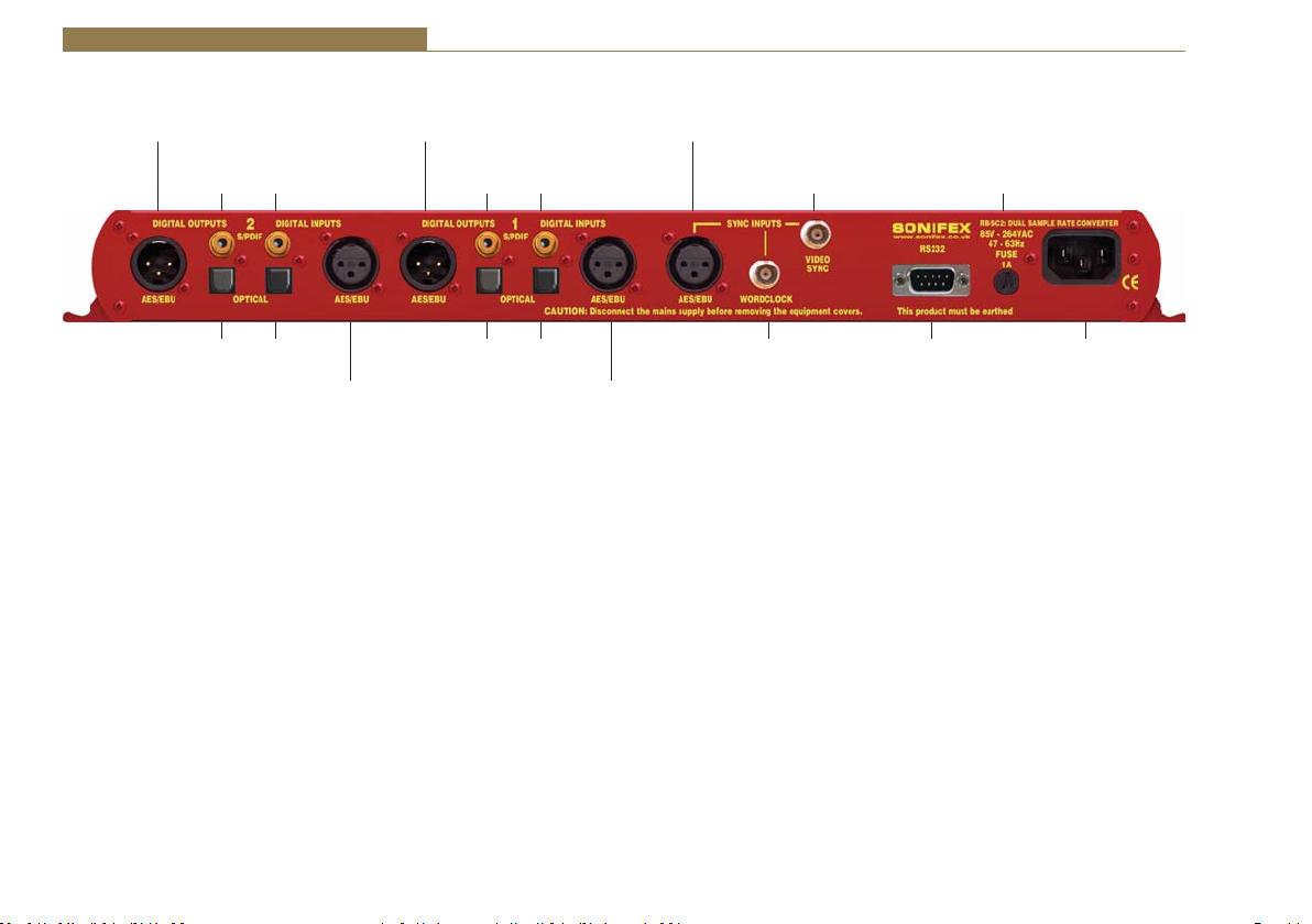
4 Digital Audio Converters - RB-SC2
Rear Panel Connections and Operation
AES/EBU
Digital Output 2
S/PDIF
Output 2
S/PDIF
Input 2
AES/EBU
Digital Output 1
S/PDIF
Output 1
S/PDIF
Input 1
AES/EBU
Sync Input
Optional Video
Sync Input
Fuse
Optical
Output 2
Fig 4-9: RB-SC2 Rear Panel
RB-SC2 Inputs
AES/EBU Inputs
dŚĞĚŝŐŝƚĂůŝŶƉƵƚy>ZϯƉŝŶƐŽĐŬĞƚŚĂƐĂŶŝŵƉĞĚĂŶĐĞŽĨϭϭϬɏ/ƚŚĂƐƚŚĞ
following connections:
Pin 1: Screen
Pin 2: Phase
Pin 3: Non-phase
The signals on this connector should meet the IEC 60968 specification
S/PDIF Inputs
dŚĞ^W/&ĚŝŐŝƚĂůƉŚŽŶŽŝŶƉƵƚŚĂǀĞĂŶŝŵƉĞĚĂŶĐĞŽĨϳϱɏ
Optical Inputs
The digital audio optical input meets the TOSLink specification used by most
professional & consumer equipment.
AES/EBU Sync Input
dŚĞĚŝŐŝƚĂůŝŶƉƵƚy>ZϯƉŝŶƐŽĐŬĞƚŚĂƐĂŶŝŵƉĞĚĂŶĐĞŽĨϭϭϬɏ/ƚŚĂƐƚŚĞ
26
Optical
Input 2
AES/EBU
Digital Input 2
Optical
Output 1
Optical
Input 1
AES/EBU
Digital Input 1
Sync Input
RS232Word Clo ck
following connections:
Pin 1: Screen
Pin 2: Phase
Pin 3: Non-phase
The signals on this connector should meet the IEC 60968 specification
Word Clock Input
dŚĞ^W/&ĚŝŐŝƚĂůƉŚŽŶŽŝŶƉƵƚŚĂǀĞĂŶŝŵƉĞĚĂŶĐĞŽĨϳϱɏ
RB-SC2 Outputs
AES/EBU Outputs
dŚĞĚŝŐŝƚĂůŽƵƚƉƵƚy>ZϯƉŝŶƐŽĐŬĞƚŚĂƐĂŶŝŵƉĞĚĂŶĐĞŽĨϭϭϬɏ/ƚŚĂƐƚŚĞ
following connections:
Pin 1: Screen.
Pin 2: Phase.
Pin 3: Non-phase.
IEC Mains
Input

Digital Audio Converters - RB-SC2 4
The signals on this connector will comply with the IEC 60968 specification
S/PDIF Outputs
dŚĞĚŝŐŝƚĂůŽƵƚƉƵƚ^W/&ƉŚŽŶŽŽƵƚƉƵƚŚĂƐĂŶŝŵƉĞĚĂŶĐĞŽĨϳϱɏ
Optical Outputs
The digital audio optical output meets the TOSLink specification used by
most professional & consumer equipment.
The outputs will have a unweighted dynamic range of at least 138dB and
a THD+N noise of or better than –137dB. The data at the outputs will be
presented as 24 bit wide.
Serial Port Control
The Serial Port allows the RB-SC2 to be controlled and updated from a PC
via a pin-to-pin serial cable, using the Sonifex Serial Control Interface (SCI)
software. This software is available as a free download from the Sonifex
website at www.sonifex.co.uk/sci.
Default Settings for the Serial Port
Baud Rate: 19200
Data Bits: 8
Stop Bits: 1
Parity: Even
Handshaking: XON/XOFF
Fig 4-10: Serial Port Default Settings
Serial Interface Commands and Responses
Most of the commands follow the same structure: a 3 letter command
followed by a colon, followed by a parameter (if any) and terminated by
Carriage Return with optional Line Feed. A Line Feed character may be sent
but it will be ignored by the RB-SC2. Commands are not case sensitive and
all parameters are in hex.
Responses are CR & LF terminated.
After the delay synchroniser has been powered-up, an initialisation string is
sent “Initialising SC2”.
Following are the commands and the expected responses:
Command Description Response
Bnn: - Baud Rate - ACK: (at old rate)
nn=11 (115200)
nn=57 (57600)
nn=38 (38400)
nn=19 (19200)
nn=96 (9600)
CSD:nn - Set Channel Status Type - ACK:
nn=00 - Send Consumer CS Data
nn=01 - Follow Input (or use last set)
nn=02 - Send Professional CS Data
DWN: - Download new code -OK: then erasing message
Then send S-records followed
by S-record terminator to force
programming of flash memory
and reboot
FPL: - Request Front Panel Limits - FPL:a_b
Where a = Lock Status (0=unlocked, 1=locked)
b = Master Frequency Limit (0=no limit, 1=48kHz,
2= 96kHz)
FPS: - Request Front Panel Settings - FPS:aa_bb_cc_dd_ee_ff
Where aa = value of Sync Mode as MOD: below
bb = value of Master Frequency as FRQ: below
cc = value of Sync Frequency as FRQ: below
dd = value of CS Data as CSD: above
ee = value of Input 1 Source Select as SS1: below
ff = value of Input 2 Source Select as SS2: below
27

4 Digital Audio Converters - RB-SC2
FRQ:nn - Set Master Clock Frequency - ACK:
nn=00 - Select 32kHz Master Clock Sample Rate
nn=01 - Select 44kHz Master Clock Sample Rate
nn=02 - Select 48kHz Master Clock Sample Rate
nn=03 - Select 88kHz Master Clock Sample Rate
nn=04 - Select 96kHz Master Clock Sample Rate
nn=05 - Select 176kHz Master Clock Sample Rate
nn=06 - Select 192kHz Master Clock Sample Rate
LOC: - Lock Front Panel - ACK:
MEM: - Memory Dump - Memory, then 10 lines
Madd:data
Where add is memory address starting at 060(hex)
and data is 16 bytes of data, each byte shown as
2 hex digits
MFQ:nn - Limit Front Panel Frequency Selection - ACK:
Where nn=0 for No Limit
nn=1 for 48kHz Limit &
nn=2 for 96kHz Limit
MOD:nn - Set Mode & Select Sync Source - ACK:
nn=00 - Master Mode
nn=08 - Auto Mode
nn=10 - Auto Lock Mode
nn=20 - Slave Mode
For last three modes add
nn=01 - Select External AES Sync input as sync source
nn=02 - Select Word Clock input as sync source
nn=03 - Select Other Digital input as sync source (X-Lock)
nn=04 - Select Optional Video input as sync source
REG: - Register Dump - Registers, then 4 lines of 8 x Rrr:dd
Where rr is register number and dd is value shown
as 2 hex digits
SER: - Serial Number request - SER:012345
SRQ: - Status Request - STA:aa_bb_ss
Where aa = SRC 1 Status
bb = SRC 2 Status
ss = Sync Status
SS1:nn - Select Channel 1 Digital Audio Source -ACK:
nn=00 for AES/EBU
nn=01 for S/PDIF &
nn=02 for Optical
SS2:nn - Select Channel 2 Digital Audio Source -ACK:
nn=00 for AES/EBU
nn=01 for S/PDIF &
nn=02 for Optical
STK: - Stack Dump - STK: aaaa, then 6 lines Sadd:data
Where aaaa= current Stack Pointer,
add is memory address starting at 0800(hex)
and data is 16 bytes of data, each byte shown as
2 hex digits
UNL: - Unlock Front Panel - ACK:
UID: - Unit ID Request - UID:SC2
VER: - Firmware Version Request - VER:1.23 or BOOT:1.23
Fig 4-11: Serial Interface Commands and Responses
Error messages
The following error messages can be returned for illegal commands
Err:01 - return if Command Not Found
Err:02 - return if Missing Parameter
Err:04 - return if Parameter out of range
Upgrading Firmware
Occasionally, it may be necessary to upgrade the firmware on the RB-SC2 to
add new functionality and fix software bugs. New firmware updates will be
made available from time to time on the Sonifex website.
Visit www.sonifex.co.uk for details.
The firmware is upgraded using the Serial Control Interface - SCI. This PC
software downloads the new firmware and initiates the upgrade process. To
upgrade the firmware, select the required firmware file in the SCI upgrade
firmware section. The RB-SC2 will automatically reboot and enter the
bootstrap mode prior to the transfer of the firmware file. The SCI software
28

Digital Audio Converters - RB-SC2 4
downloads the firmware to internal memory, and then erases the current
firmware before programming the update. When the firmware is complete,
the unit reboots with the new firmware.
Please note: Firmware files can take several minutes to transfer to the
RB-SC2 at lower baud rates. To speed up the process, select a higher baud
rate prior to transferring the new firmware.
Technical Specification RB-SC2
Audio Specification
Dynamic Range: 138dB typical A-Weighted.
Distortion & Noise: -134dB THD + N at 1kHz, ref 0 dBFS
Sample Freq Range: 32kHz – 196kHz
Input Sample Width: Up to and including 24 Bits.
Output Sample Width: 24 Bits.
Connections
Digital Inputs: 2 x AES/EBU XLR 3 pin female
2 x S/PDIF RCA phono
2 x TOSLink optical input
Digital Outputs: 2 x AES/EBU XLR 3 pin plug
2 x S/PDIF RCA phono socket
2 x TOSLink optical output
Sync Inputs: 1 x AES/EBU XLR 3 pin female
1 x Word Clock BNC
1 x Video Input (optional)
Video Sync Specs: The RB-SYD Digital video sync board will accept
270Mbps SD-SDI and HD-SDI signals covered by
SMPTE-259-M-C (SD) and SMPTE-292M (HD).
The RB-SYA Analogue video sync board will
accept a composite signal of NTSC (525), PAL
(625) & SECAM (625) signals covered by
SMPTE-170-M (NTSC) and ITU-R BT.470-6
(PAL & SECAM).
Operational Controls
Master Frequency Select: 32, 44.1, 48, 88.2, 96,176.4 or 192kHz via
FREQUENCY push-button
Channel Status Bits: Consumer mode, professional mode or follow
input, via CS DATA push-button
Digital Input Select: AES/EBU, S/PDIF or TOSlink optical, via INPUT1
or INPUT2 push-buttons
Sync Input Select: AES/EBU, Word Clock, X-Lock or Video, via SYNC
push-button
Sync Mode Select: Master, slave, auto or auto lock, via SYNC
push-button
Other Connections
Mains Input: Universal filtered IEC, continuously rated
85-264VAC @47-63Hz, max 10W
Serial Port: RS232 9 Pin D-type socket
Equipment Type
RB-SC2 Dual Stereo Sample Rate Converter,
24 bit 192kHz
Physical Specifications
Dimensions (Raw) 48cm (W) x 10.8cm (D*) x 4.2cm (H) (1U)
19” (W) x 4.3” (D*) x 1.7” (H) (1U)
Dimensions (Boxed) 59cm (W) x 27.5cm (D) x 11cm (H)
23.2” (W) x10.8” (D) x 4.3” (H)
Weight Nett: 1.4kg Gross: 2.0kg
Nett: 3.1lbs Gross: 4.4lbs
Accessories
RB-SYA Analogue video sync board (NTSC, PAL
& SECAM)
RB-SYD Digital video sync board (SD-SDI & HD-SDI)
RB-RK3 1U Rear panel rack kit for large Redboxes
29

5 Digital Audio Converters - RB-DAC1
5 RB-DAC1 Digital to Analogue Converter
Introduction
Fig 5-1: RB-DAC1 Front Panel
Using 24 bit, 192kHz capable devices, the RB-DAC1 Digital
to Analogue Converter is a 1U rack-mount which produces
a stereo balanced XLR or unbalanced phono output from an
2
9
1
System Block Diagram
Fig 5-2: RB-DAC1 System Block Diagram
30
incoming AES/EBU or S/PDIF digital input signal. There is
also a headphone output for monitoring purposes.
AES/EBU
Digital
Input
S/PDIF
Digital Source
Selector
AES
Receiver
The analogue outputs have an output level control, allowing full-scale
settings selectable from +12dBu, +18dBu or +24dBu. De-emphasis on the
output can be enabled via dipswitch.
There is a button to select either the AES/EBU or S/PDIF input for the D/A
converter, which is located on the rear panel.
When operating, the front panel power LED flashes whenever the unit is
not synchronised to the incoming digital signal.
Volume Control
Stereo
Headphone
Output
L
Professional
Output
DAC
R
L
Consumer
Output
R
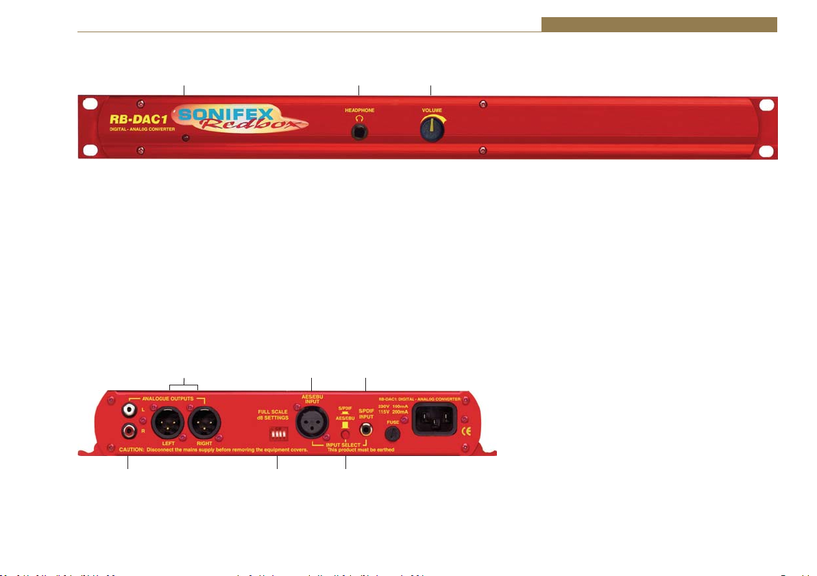
Front Panel Indicators & Controls
Sync & Power Indicator Headphone Output Volume Control
Fig 5-3: RB-DAC1 Front Panel
Sync & Power Indicator
The LED on the front panel is normally red to indicate that power is present
on the unit. However, it also has a secondary role to indicate the status of
the digital inputs :
Flashing between red and amber – indicates a loss of a valid digital input
signal.
Rear Panel Connections and Operation
Digital Audio Converters - RB-DAC1 5
Headphone Output
The output available on the front panel through a ¼” stereo jack socket, is
ĚĞƐŝŐŶĞĚƚŽĚƌŝǀĞϭϱϬŵtŝŶƚŽϯϮɏƚŽϲϬϬɏƉƌŽĨĞƐƐŝŽŶĂůŚĞĂĚƉŚŽŶĞƐ
Volume Control
The headphone output has its own volume control, which is independent of
the level adjustment for the main outputs, and has a maximum output level
of +20dBu.
Analogue
Outputs (L&R)
RCA Phono
Outputs (L&R)
Fig 5-4: RB-DAC1 Rear Panel
AES/EBU
Input
Full Scale Digits and
De-Emphasis Switches
S/PDIF
Input
Digital Select
Button
31

5 Digital Audio Converters - RB-DAC1
RB-DAC1 Inputs
AES/EBU Input
dŚĞĚŝŐŝƚĂůŝŶƉƵƚy>ZϯƉŝŶƐŽĐŬĞƚŚĂƐĂŶŝŵƉĞĚĂŶĐĞŽĨϭϭϬɏ/ƚŚĂƐƚŚĞ
following connections:
Pin 1: Screen
Pin 2: Phase
Pin 3: Non-phase
The signals on this connector should meet the IEC 60968 specification
S/PDIF Input
dŚĞ^W/&ĚŝŐŝƚĂůƉŚŽŶŽŝŶƉƵƚŚĂƐĂŶŝŵƉĞĚĂŶĐĞŽĨϳϱɏ
RB-DAC1 Outputs
Analogue Outputs (Left and Right)
The XLR 3 pin output plug connectors are electronically balanced with an
ŽƵƚƉƵƚŝŵƉĞĚĂŶĐĞŽĨůĞƐƐƚŚĂŶϱϬɏdŚĞLJŚĂǀĞƚŚĞĨŽůůŽǁŝŶŐĐŽŶŶĞĐƚŝŽŶƐ
Pin 1: Screen.
Pin 2: Phase.
Pin 3: Non-phase.
RCA Phono Outputs (Left and Right)
These RCA (phono) outputs are unbalanced and have an output impedance
ŽĨůĞƐƐƚŚĂŶϳϱɏ
Rear Panel Controls
Full Scale dB Settings
Switch Number +12 +18 +24
1 OFF ON ON
2OFFOFFON
Emphasis Settings
3 ON De-emphasis On
3 OFF De-emphasis Off
4 Reserved
Fig 5-5: RB-DAC1 Full Scale Digits and De-emphasis Settings Switches
Output Level Adjustment
The output gain can be adjusted by dipswitches on the rear panel. The
output gain can be set for a signal of full-scale digits in the digital domain
to give +12, +18 or +24dBu output on the XLR connectors. The consumer
output on the phono connector has a further 8½dBu attenuation
incorporated.
De-emphasis Switch
If de-emphasis is selected (switch 3) the RB-DAC1 will decode 50/15μs
emphasis when indicated by certain channel status bits in the incoming
digital audio data.
Digital Select Button
This button is used to switch the digital input from the AES/EBU XLR
connector (button out) to the S/PDIF phono connector (button in).
32

Technical Specifications RB-DAC1
Digital Audio Converters - RB-DAC1 5
Connections
Digital Inputs: 1 x AES/EBU XLR 3 pin female
1 x S/PDIF RCA phono
Analogue Outputs: 2 x XLR 3 pin male (balanced) (L & R)
2 x RCA phono (unbalanced) (L & R)
Headphone Output: 1 x ¼” (6.35mm) A/B gauge 3-pole stereo
jack socket
Mains Input: Filtered IEC, 110-120V, or 220-240V switchable,
fused 18W max
Fuse Rating: Anti-surge fuse 100mA 20 x 5mm (230VAC)
Anti-surge fuse 250mA 20 x 5mm (115VAC)
Audio Specification Balanced
Maximum Output
Level:
Output Impedance:
Dynamic Range: 115dB 115dB 100dB
Gain Range:
Distortion & Noise: <0.005%
Sample Freq. Range:
Output
+24dBu +15.5dBu +20dBu (ref.
фϱϬё фϳϱё Drives 150mW
Selectable
12dBu, 18dBu
or 24dBu
output level,
ref FSD
THD+N @1kHz,
ref +8dBu
32kHz - 192kHz
Unbalanced
Output
Selectable
3.5dBu,
9.5dBu or
15.5dBu output
level, ref FSD
<0.005%
THD+N @1kHz,
ref -6dBV
Headphone
Output
<0.01% THD)
ŝŶƚŽϯϮɏƚŽϲϬϬɏ
professional
headphones
-80dBu (volume
0%) to
+20dBu (volume
100%)
ref FSD
<0.005%
THD+N @1kHz,
ref +8dBu
Operational Controls
Digital Input Select: AES/EBU or S/PDIF, via push-switch
Gain Select: Selectable 12dBu, 18dBu or 24dBu output level,
ref. FSD
De-emphasis
On/Off: Dipswitch
Equipment Type
RB-DAC1 Digital to Analogue Converter
Physical Specifications
Dimensions (Raw): 48cm (W) x 10.8cm (D) x 4.2cm (H) (1U)
19” (W) x 4.3” (D) x 1.7” (H) (1U)
Dimensions (Boxed): 58.5cm (W) x 22.5cm (D) x 7cm (H)
23” (W) x 8.9” (D) x 2.8” (H)
Weight: Nett: 1.4kg Gross: 2.0kg
Nett: 3.1lbs Gross: 4.4lbs
33

6 Digital Audio Converters - RB-SP1
6 RB-SP1 Digital Splitter & Combiner
Introduction
Fig 6-1: RB-SP1 Front Panel
The RB-SP1 Digital Splitter & Combiner is used to interface
various double sampling pieces of equipment. Some older
equipment uses 2 AES/EBU connectors for double sampling
with each connector carrying an audio signal at a normal
frame rate, whilst other equipment has a single connector using twice the
frame rate. The RB-SP1 can interface between them, either combining the
signals from 2 XLR’s into 1, or splitting the signal from 1 XLR into 2.
The RB-SP1 can also be used for interfacing stereo and mono signals to
digital mixing desks by splitting the left and right signals of a stereo XLR to
two separate XLR’s, and vice versa by combining them.
System Block Diagram
Digital
Digital
Input 1
Input
Select
Receiver
Additionally, a sample rate converter on the second digital input can be
used to convert the sample rate of the secondary input to that of the
primary input. The RB-SP1 can handle sample rates up to 96kHz and sample
sizes of 16, 20 and 24 bit.
There are two types of operation : Split 96, and Stereo/Mono. These each
have three different switch modes : Split, Bypass and Combine.
Both inputs and outputs can be selected as either AES/EBU or S/PDIF with
the resultant digital level following the switch selection.
Digital
Transmitter
Router
Output
Select
Digital
Output 1
Digital
Input 2
Receiver
Combine & Bypass Mode Only Split Bypass Mode Only
Fig 6-2: RB-SP1 System Block Diagram
& SRC
Transmitter
34
Digital
Output 2

Digital Audio Converters - RB-SP1 6
Front Panel Indicators & Controls
Fig 6-3: RB-SP1 Front Panel
Front Panel LED’s
There are four LED indicators situated on the front of the unit. The red LED
on the far left of the front panel is to indicate that power is present on the
unit.
The three LED’s grouped together on the right hand side have two roles,
see Fig 6-3. The first is to indicate the synchronisation frequencies of the
incoming digital signals, and the second is to flash when a signal has been
lost. These indicators are labelled individually to show the current sync
frequencies.
Type & Mode Switches
The Type and Mode switches are on the front panel – see Fig 6-3. The
Type switch sets the unit into either the Split 96 or Stereo/Mono style of
operation. The Mode switch sets the unit into Split, Bypass or Combine
mode.
See Figure 6-4 for diagrammatic explanations of the different types and
modes available.
Split 96 – This is a method that allows older equipment to handle 48kHz
double sampled (96kHz) digital signals. To do this, Split 96 uses two digital
signals running at 48kHz, where both sub-frames of a single 48kHz stream
are used to carry information about a mono signal, with the resultant signal
of both 48kHz streams being equivalent to a stereo 96kHz signal. The unit
will also perform the same function for 88.2kHz stereo and 44.1kHz double
sampled signals.
• In Split Mode a single stereo 96kHz signal is received into input 1 which
is then output as two separate 48kHz signals. Output 1 will contain just
left channel data and output 2 will contain just right channel data. If the
signal from the input disappears then both Outputs will be muted.
• In Combine Mode two 48kHz double sampled input signals are combined
to create a single 96kHz signal on output one. If either input 1 or 2 are
lost then the output will be muted. In this mode output 2 will always be
muted.
Stereo/Mono – This allows a digital stereo signal to be separated into two
mono digital signals and vice-versa.
• In Split Mode a single stereo digital signal is routed to two digital
outputs. Output 1 will contain the original left channel data on its left
output and a muted signal on its right output. Output 2 will contain
the original right data on its left output and a muted signal on its right
output. This mode can be altered by the dipswitch settings, to a channel
swap mode or a dual mono mode. These are described in more detail in
the Rear Panel Controls section below.
• In Combine Mode two mono signals are combined to create a single
stereo signal. Output 1 will contain the input 1 left channel data on its
left channel and input 2 left channel data on its right channel. This mode
can be altered by a dipswitch setting, as with the split mode. Where
either the left or right channel data of input 2 is output on the right
channel data of the output. If the two signals are of different sample
rates, a sample rate converter can be switched in place to convert the
sample rate of input channel 2 to that of input channel 1. In the Stereo/
Mono Combine mode, output 2 is always muted.
Bypass Mode – In Bypass mode, input 1 is routed to output 1 and input 2 is
routed to output 2. Input 1 is used as the master clock input. If input 2 is at
a different sample rate to input 1 then input 2 is sample rate converted to
match input 1. If the signal from input 2 is lost then output 2 will be muted.
However, if the signal from input 1 is lost then both outputs will be muted
and will only return once a signal is present on input 1.
35

6 Digital Audio Converters - RB-SP1
A
Note that when the unit is operating in Bypass Mode the Type switch is ignored.
Split 96
SRC
O/P 1
O/P 2
O/P 1
L
L
R
R
L
R
48kHz double sampled
48kHz double sampled
96kHz
Split
Combine
48kHz double sampled
48kHz double sampled
96kHz
I/P 1
L
R
I/P 1
L
L
I/P 2
R
R
Bypass
SRC
O/P 1
O/P 2
L
R
Sample Rate 1
L
R
Sample Rate
Sample Rate 2
I/P 1
1
L
R
I/P 2
L
R
Rear Panel Connections and Operation
AES/EBU
Inputs
Digital Input &
Output Select
Buttons
AES/EBU
Outputs
Mode Select
Dip Switches
Stereo/Mono
Split
ny Sample Rate
Combine
Sample Rate 1
Sample Rate 2
X
R
Dipswitch 1OnDipswitch 1
Fig 6-4: RB-SP1 Type and Mode Flow Diagrams
I/P 1
L
R
I/P 1
L
X
I/P 2
R
X
Off
SRC
Dipswitch 3
Off
O/P 1
L
Mute
O/P 2
Mute R
Dipswitch 1
Off
O/P 1
L
R
Dipswitch 3
On
L
L
MuteR
R
Dipswitch 1
On
Sample Rate 1
X = Input Ignored
R
Dipswitch 3
On
Fig 6-5: RB-SP1 Rear Panel
36
S/PDIF
Inputs
S/PDIF
Outputs

Digital Audio Converters - RB-SP1 6
Inputs and Outputs
AES/EBU Inputs
dŚĞĚŝŐŝƚĂůƐŽƵƌĐĞy>ZϯƉŝŶƐŽĐŬĞƚƐŚĂǀĞĂŶŝŵƉĞĚĂŶĐĞŽĨϭϭϬɏdŚĞLJŚĂǀĞ
the following connections and meet the IEC 60968 specification:
Pin 1: Screen
Pin 2: Phase
Pin 3: Non-phase
S/PDIF Inputs
dŚĞĚŝŐŝƚĂůƐŽƵƌĐĞZƉŚŽŶŽŝŶƉƵƚƐďŽƚŚŚĂǀĞĂŶŝŵƉĞĚĂŶĐĞŽĨϳϱɏ
AES/EBU Outputs
dŚĞĚŝŐŝƚĂůŽƵƚƉƵƚy>ZϯƉŝŶƉůƵŐƐŚĂǀĞĂŶŝŵƉĞĚĂŶĐĞŽĨϭϭϬɏdŚĞLJŚĂǀĞ
the following connections and meet the IEC 60968 specification:
Pin 1: Screen
Pin 2: Phase
Pin 3: Non-phase
S/PDIF Outputs
dŚĞĚŝŐŝƚĂůŽƵƚƉƵƚ^W/&ƉŚŽŶŽŽƵƚƉƵƚƐŚĂǀĞĂŶŝŵƉĞĚĂŶĐĞŽĨϳϱɏ
Rear Panel Controls
Digital Input & Output Select Buttons
These buttons are used to switch the digital connection between the AES/
EBU XLR connector (button out) and the S/PDIF phono connector (button
in) for the digital source and digital output.
Mode Select Dip Switches
RB-SP1 Mode Select Settings
1 ON Input 1 Channel B = Output 2 Channel B in Stereo/Mono
Split Mode
1 OFF Input 1 Channel B = Output 2 Channel A in Stereo/Mono
Split Mode
2ONSRC Enabled
2 OFF SRC Disabled
3 ON Dual Mono in Stereo/Mono Split Mode
3 OFF Single Mono in Stereo/Mono Split Mode
4 Reserved
Fig 6-6: RB-SP1 Mode Select Dip Switches
Altering the Stereo/Mono Split/Combine Mode – In Split mode With
switch 1 off, channel A (Left) and B (Right) on the input are transferred to
channel A (Left) of outputs 1 and 2 respectively. With switch 1 on, channel
A (Left) on the input is transferred to channel A (Left) on output 1 and
channel B (Right) on the input is transferred to channel B (Right) of output
2. With switch 3 on (switch 1 is ignored), channel A (Left) is transferred to
both channels on output 1 and channel B (Right) on the input is transferred
to both channels on output 2.
In Combine mode with switch 1 off, channel A (Left) on input 1 is
transferred to channel A (Left) of output 1, and channel A (Left) on input 2
is transferred to channel B (Right) of output 1. With switch 1 on channel A
(Left) on input 1 is transferred to channel A (Left) of output 1, and channel
B (Right) on input 2 is transferred to channel B (Right) of output 1.
37

6 Digital Audio Converters - RB-SP1
Switching on the Sample Rate Converter - Switch 2 is used to turn the
sample rate converter on, or off and can be used in all modes. When there
are two inputs connected to the unit which are at different sample rates
or which need to be synchronised, then the sample rate converter should
be switched on. If it is not, then you may suffer from missed samples and
bit errors affecting the signal output. If the sample rates of the incoming
signals are always going to be the same and are synchronised, then switch
the sample rate converter off, as leaving it on will worsen the output signal
(signal jitter will increase).
Technical Specifications RB-SP1
Audio Specifications
/ŶƉƵƚ/ŵƉĞĚĂŶĐĞ ϭϭϬɏцϮϬйďĂůĂŶĐĞĚ;^hͿ
/ŶƉƵƚ/ŵƉĞĚĂŶĐĞ ϳϱɏцϱйƵŶďĂůĂŶĐĞĚ;^W/&Ϳ
KƵƚƉƵƚ/ŵƉĞĚĂŶĐĞ ϭϭϬɏцϮϬйďĂůĂŶĐĞĚ;^hͿ
KƵƚƉƵƚ/ŵƉĞĚĂŶĐĞ ϳϱɏцϱйƵŶďĂůĂŶĐĞĚ;^W/&Ϳ
Signal Level 3V/10V peak to peak min/max (AES/EBU)
0.5V ±20% peak to peak (S/PDIF)
Sample Freq Range: 30-100kHz (i.e. including 32kHz, 44.1kHz,
48kHz, 64kHz, 88.2kHz and 96kHz)
Connections
Audio Inputs: 2 x AES/EBU XLR 3 pin female
2 x S/PDIF RCA phono female
(Input button select between AES/EBU and
S/PDIF)
Audio Outputs: 2 x AES/EBU XLR 3 pin male
2 x S/PDIF RCA phono female
(Output button selects between AES/EBU and
S/PDIF)
Mains Input: Filtered IEC, continuously rated 85-264VAC
@ 47-63Hz max 10W
Fuse Rating: Anti-surge fuse 1A 20 x 5mm
Equipment Type
RB-SP1 Digital splitter & combiner
Physical Specifications
Dimensions (Raw) 48cm (W) x 10.8cm (D) x 4.2cm (H) (1U)
19” (W) x 4.3” (D) x 1.7” (H) (1U)
Dimensions (Boxed) 58.5cm (W) x 22.5cm (D) x 7cm (H)
23” (W) x 8.9” (D) x 2.8” (H)
Weight Nett: 1.6kg Gross: 2.2kg
Nett: 3.5lbs Gross: 4.8lbs
38

Synchronisation Add-On-Boards 7
7 Redbox - Synchronisation Add-On Boards
Introduction
There are two optional video sync boards which can be used to synchronise the outputs of the RB-SC2 to a 48kHz sample rate: the RB-SYA and the RB-SYD.
There are four optional video sync boards which can be used to synchronise the outputs of the RB-TGHD(B & X): the RB-SYA, RB-SYD, RB-SYE and the
RB-SYW.
RB-SYA Analogue Video Sync Board
The Analogue video sync board will accept a composite signal of NTSC
(525), PAL (625) & SECAM (625) signals covered by SMPTE-170-M (NTSC)
and ITU-R BT.470-6 (PAL & SECAM
Fig 7-1: RB-SYA Analogue Video Sync Board For RB-SC2 (PAL, NTSC, SECAM)
RB-SYD Digital Video Sync Board
The Digital video sync board will accept 270Mbps SD-SDI and HD-SDI signals
covered by SMPTE-259-M-C (SD) and SMPTE-292M (HD).
Fig 7-2: RB-SYD Digital Video Sync Board For RB-SC2 (HD-SDI, SD-SDI)
39

7 Synchronisation Add-On-Boards
RB-SYE Sync Board
The AES/EBU sync board will accept a digital audio input signal with a
sample frequency between 32kHz and 192 kHz. When using the RB-SYE sync
board, the Channel Status information that is encoded in the input data
signal is copied to all digital output channels on the RB-TGHD.
RB-SYW Sync Board
The Audio Clock sync board will accept a distributed clock running at the
desired sample frequency between 32 kHz and 192 kHz. Thesignal can be
differential or single ended TTL level.
Fig 7-3: RB-SYE Sync Board
40
Fig 7-4: RB-SYW Sync Board

Synchronisers & Delays - RB-DS2 8
8 RB-DS2 Stereo Delay Synchroniser & Time Zone Delay
Introduction
Fig 8-1: RB-DS2 Front Panel
The RB-DS2 is a stereo audio delay synchroniser used for resynchronising
audio to video following delay processes such as standards conversion,
transmission delay, logo insertion, video aspect ratio conversion and
network delays. It can be used for fixed installations to correct a
permanent audio delay, or on an intermittent basis to provide occasional
correction, for example for live links. Accepting digital audio signals up to
96kHz, 24 bit, the sonic quality of the RB-DS2 is superb and silent switching
is used to provide the smoothest, cleanest audio delay available.
The RB-DS2 has both balanced analogue and AES/EBU digital audio inputs
and outputs on 3 pin XLR connectors. It can act as a combined A/D and D/A
unit meaning that analogue inputs can be delayed and output as AES/EBU
and vice-versa. It is a stereo delay, but can also be used as a dual mono
delay to process each audio path separately, or as a mono delay using the
left inputs and outputs.
As standard the RB-DS2 can provide up to 10.5 seconds of delay at 96kHz
sampling, 24 bit (42 secs at 48kHz, 16 bit). An internal Compact Flash™
expansion allows up to 16GB of memory to be accessed providing delay
times of over 24 hours, for example, to delay a programme output across
different time-zones, or to shift a broadcast programme by 1 hour for
a satellite rebroadcast. Delay times can be selected in samples, fields,
frames, milliseconds, metres and, with the Compact Flash™ expansion, in
hh:mm:ss. Frame and field definitions can be for PAL (25 frame) or NTSC
(30 frame) signals.
A front panel blue vacuum fluorescent display with rotary controller is
used for selecting the various settings of the delay, which include the
source (analogue or digital), channels, sample rate, sample bit width,
format (PAL or NTSC), delay units and the delay itself. Additionally, input
peak digits can be selected from +12dBu, +18dBu and +24dBu for FSD
and two left and right pre-set potentiometers on the rear panel allow
the input gain range to be altered by ±3dB around the selected peak
digits.
The analogue output gain range can be altered from -6dBu to +24dBu
output level, ref FSD.
Both analogue and digital outputs can be separately muted and a front
panel Bypass button disengages electro-mechanical relays to divert both
analogue and digital inputs to their outputs. This is also disengaged
automatically when a power-fail occurs.
All of the settings in the unit can be saved to one of 8 configuration
settings. These Configs can be viewed, edited, saved and loaded, and
also remotely loaded by using one of the 8 GPI contacts, meaning that
any setting, such as delay time or Bypass, can be altered instantaneously
using a GPI signal. Alternatively, 6 of the GPI/O ports can be configured
to provide delay synchronous signalling where an input is delayed by
the current delay before driving a corresponding output. The RB-DS2
also has an RS232 serial port for remotely controlling the unit. The front
41

8 Synchronisers & Delays - RB-DS2
panel controls can be locked-out for situations where remote control is
being used to run the unit, or where physical security is required.
Extended Mode using Compact Flash™
Extended mode allows the delay synchroniser to provide audio delays
in excess of 24 hours so that the unit can act as a broadcast time-zone
delay. The memory card slot is internally mounted and currently supports
Compact Flash™ cards up to 16Gbytes - see page 54 for information on
opening the RB-DS2 to insert a CF card. To operate correctly, the flashcard
must support PIO Mode 4, or higher, such as the SanDisk Standard CF cards.
There are 2 extended modes, FAT and RAW.
Extended FAT Mode
This mode supports cards up to 2Gbytes in size and the delay synchroniser
uses the DOS format with a 16bit FAT. If a Compact Flash™ memory card is
installed in the internal card slot, the status of the card will be indicated in
the lower right side of the display. If the card is not formatted, or the format
is corrupted, the display will show “NOFMT” indicating that the card cannot
be written to until it has been formatted (see System Menu: Memory Card
for details on formatting the card). When the card is correctly formatted,
the capacity is shown in Mbytes. The delay synchroniser generates a file
on the Compact Flash™ memory card, prior to starting the delay process,
which effectively reserves all the space available and provides for the
largest possible delay. If the Compact Flash™ memory card was removed
and placed in a PC card reader, the file, named “RB-DS2.WAV”, would play
using any utility that’s supports Broadcast Wave Format - PCM files.
Extended RAW Mode
This mode supports cards up to 16Gbytes in size and the delay synchroniser
can use the full card capacity for the delay. The card does not require
formatting in this mode as no filing system is created, and the contents
will not be available to read in a PC card reader. This means that maximum
delays for cards up to 2Gbytes will be slightly larger when using this mode
compared to Extended FAT mode.
Note: Extended Mode can only be used for mono and stereo CHANNELS
settings, not for dual mono signals.
42

System Block Diagram
Synchronisers & Delays - RB-DS2 8
AES/EBU
Digital
Bypass
Digital
Input
AES/EBU
L
R
Analogue
Inputs
Fig 8-2: RB-DS2 System Block Diagram
Control
Analogue
Bypass
Control
Gain
Gain
AES
Receiver
Recovered
Clock
Master
Clock
Generator
ADC DAC
Front Panel Controls
All of the RB-DS2’s configurations can be accessed with the single front
panel mounted rotary control in conjunction with the vacuum fluorescent
display.
CONT RO L
Fig 8-3: Front Panel CONTROL
SELECT MENU
SELECT DELAY
HOLD
AES/EBU
Gain
Gain
Digital
Bypass
Control
Professional
Analogue
Bypass
Control
Digital
Output
Balanced
Analogue
Outputs
L
R
AES
Transmitter
Source
select &
Delay Control
Setting the Delay
To adjust the delay, lightly press the rotary CONTROL to enable the delay
select mode. A solid line will appear under the selected digit. To change
the selected digit, turn the rotary control. When configured for dual mono
operation, the selection highlight will move between left and right channel
delay values. Once the required digit is highlighted, press the rotary control
to switch to delay edit mode. The highlight under the selected digit will
begin to flash indicating that delay edit mode is enabled. The value of the
selected digit can be changed, by turning the rotary control. When the
selected digit is set to the required value, press the rotary control again
to return to the delay select mode. A different digit can now be selected.
43

8 Synchronisers & Delays - RB-DS2
If no further digit is selected, delay select mode will be disabled and the
selection highlight will disappear after 2.5 seconds.
Changes to the delay are implemented dynamically. If the selected delay
value exceeds the amount of audio data that has been stored, the analogue
and digital outputs will be muted until the required delay has been
acquired. The audio will then be presented at the outputs. In extended
mode, where the memory card installed in the internal Compact Flash™
Storage Card Slot is used, delay periods can be in excess of 1 hour. During
acquisition of long delays in extended mode, a progress bar is displayed
to give an indication of when the audio output will start. The size of the
progress bar decreases as the delay is acquired.
The delay value that can be set cannot exceed the maximum delay for the
selected mode. For example, for an analogue input sampled at 96kHz,
24bit, using 25fps, the maximum delay in frames for normal mode is 268
(see figures 4, 5 and 6 for maximum delay values).
Selecting The Main Menu
The RB-DS2’s configuration options are accessed from the main system
menu. To access the main system menu, press and hold the rotary
Rear Panel Connections and Operation
CONTROL for at least 1.5 seconds. The menu structure is arranged in a
multi-tiered format with several menu items providing access to submenus. To select a menu item, turn the rotary control until the required
item is highlighted, then press the rotary control to select the item. Each
configuration is shown as a list of available options. The currently selected
option will be shown with a tick along side it. The last item shown in each
menu is XCLOSE. Selecting close exits the system menu and returns to the
main display. In each sub-menu, the penultimate item shown is WBACK.
Selecting back displays the previous menu.
Bypassing The Delay
The Bypass button enables the delay bypass mode, which internally
connects the inputs to outputs in both the analogue and digital domains.
The Bypass button is illuminated when the delay bypass mode is enabled.
When power is removed from the unit, the bypass mode is automatically
enabled.
System Reset
A single LED on the left side of the front panel indicates that power is
applied to the unit. The system reset button is accessible through the small
aperture to the right of the
power LED.
Fig 8-4: RB-DS2 Rear Panel
44

Synchronisers & Delays - RB-DS2 8
XLR Analogue Inputs (Left and Right)
The XLR 3 pin sockets used for the left and right channel analogue inputs
ĂƌĞĞůĞĐƚƌŽŶŝĐĂůůLJďĂůĂŶĐĞĚĂŶĚŚĂǀĞĂŶŝŵƉĞĚĂŶĐĞŐƌĞĂƚĞƌƚŚĂŶϭϬŬɏ
bridging. Each XLR has the following connections:
Pin 1: Screen
Pin 2: Phase
Pin 3: Non-phase
Analogue Input Adjustment
The Input Peak Digits setting (see System Menu: Volume) sets the
analogue input gain for full-scale digits in the digital domain. The preset
potentiometers next to the analogue inputs allow an additional adjustment
of this value by ±3dB.
AES/EBU Input
dŚĞĚŝŐŝƚĂůŝŶƉƵƚy>ZϯƉŝŶƐŽĐŬĞƚŚĂƐĂŶŝŵƉĞĚĂŶĐĞŽĨϭϭϬɏ/ƚŚĂƐƚŚĞ
following connections:
Pin 1: Screen
Pin 2: Phase
Pin 3: Non-phase
The signals on this connector should meet the IEC 60968 specification.
XLR Analogue Outputs (Left and Right)
The XLR 3 pin output plugs are electronically balanced with an output
ŝŵƉĞĚĂŶĐĞŽĨůĞƐƐƚŚĂŶϱϬɏdŚĞLJŚĂǀĞƚŚĞĨŽůůŽǁŝŶŐĐŽŶŶĞĐƚŝŽŶƐ
Pin 1: Screen
Pin 2: Phase
Pin 3: Non-phase
AES/EBU Output
dŚĞĚŝŐŝƚĂůŽƵƚƉƵƚy>ZϯƉŝŶƉůƵŐŚĂƐĂŶŝŵƉĞĚĂŶĐĞŽĨϭϭϬɏ/ƚŚĂƐƚŚĞ
following connections:
Pin 1: Screen
Pin 2: Phase
Pin 3: Non-phase
The signals on this connector comply with the IEC 60968 specification.
Remote Inputs and Outputs
The 15-way ‘D’ type socket connector presents 8 active low inputs and 6
open collector outputs. The inputs are used to remotely select one of 8
configuration setups (see System Menu: Setups) when the Remote Loading
function is enabled. When the Remote Loading function is disabled, input
and outputs 1-6 can be configured to provide delayed GPI/O (see System
Menu: Remotes). The connector has the following connections:
Pin 1: Active low input 1
Pin 2: Active low input 2
Pin 3: Active low input 3
Pin 4: Active low input 4
Pin 5: Active low input 5
Pin 6: Active low input 6
Pin 7: Active low input 7
Pin 8: Active low input 8
Pin 9: Signal ground
Pin10: Open collector output 1
Pin11: Open collector output 2
Pin12: Open collector output 3
Pin13: Open collector output 4
Pin14: Open collector output 5
Pin15: Open collector output 6
RS232
The 9-way ‘D’ type socket connector allows direct connection to a serial
port on a PC via a pin-to-pin cable. See the section on Serial Port Control for
details of this interface. It has the following connections:
Pin 1: n/c
Pin 2: Transmit data (TxD)
Pin 3: Receive data (RxD)
Pin 4: n/c
Pin 5: Ground
45

8 Synchronisers & Delays - RB-DS2
Pin 6: n/c
Pin 7: Clear To Send (CTS)
Pin 8: Request To Send (RTS)
Pin 9: n/c
The Default Screen
The default screen (Fig 8-5) shows the current selections for audio source,
ate, delay units and delay. In stereo mode, the delay is common to
sample r
both left and right channels. In dual mono mode, the delay for the left and
right channels is shown separately as each channel is delayed individually.
Also shown on the main screen is the mute status of the analogue and
digital outputs and the currently selected frame rate and sample size. All
of the Audio Delay Synchronisers’ settings are configured from the main
system menu with the exception of the actual delay. The delay is adjusted
directly from the main screen following the instructions on page 43.
SOURCE: ANALOGUE
RATE: 48KHZ
DELAY: SAMPLES
L+R: 0004800
Fig 8-5: The Default Screen
AAD
25FPS
24BIT
The Main Menu
To access the main menu, press and hold the rotary CONTROL knob and
follow the instructions on page 44.
MAIN MENU
MODE
SOURCE
CHANNELS
SAMPLE RATE
SAMPLE WIDTH
FORMAT
DELAY UNITS
VOLUME
SETUPS
REMOTES
MEMORY CARD
CONTROL LOCK
SYSTEM
CLOSE
Fig 8-6: The Main Menu
Mode
This option selects which memory is used for the audio delay process. From
the main system menu select MODE. The available options are NORMAL,
EXTENDED CF (FAT) and EXTENDED CF (RAW). Changing the mode will force
the analogue and digital audio outputs to be muted as the current delay
duration is reset and the delay is acquired on the new media. See figures
8-7, 8-8 and 8-9 for the maximum delays in each mode.
• Normal – This mode selects the internal RAM to be used for the delay
process. The size of the internal memory used is 8232960 bytes.
46

Synchronisers & Delays - RB-DS2 8
• Extended CF (FAT) – This mode selects the Compact Flash™ memory card
loaded in the internal memory card slot. This mode supports Compact
Flash™ cards up to 2Gbytes and uses a PC readable filing system. If this
Extended mode is selected with no Compact Flash™ memory installed, a
message box will be display and the audio output will not be interrupted.
• Extended CF (RAW) – This mode selects the Compact Flash™ memory
card loaded in the internal memory card slot. This mode supports
Compact Flash™ cards up to 16Gbytes. If this Extended mode is selected
with no Compact Flash™ memory installed, a message box will be display
and the audio output will not be interrupted.The default mode is Normal.
Source
This option selects which input is used for the audio delay process.
From the main system menu select SOURCE. The available options are
ANALOGUE, ANALOGUE SYNC and DIGITAL. The delayed audio appears
at both the analogue and digital outputs regardless of the input source
selected.
• Analogue – This selects the audio at the analogue inputs as the source
for the delay. The input is sampled and delayed using the selected
sample rate generated from an internal master clock. The digital input is
not used.
• Analogue Sync – This selects the audio at the analogue inputs as the
source for the delay. The input is synchronised to the digital audio sync
signal at the digital input and the analogue and digital audio outputs will
be muted until a valid sync signal is detected. Once a valid sync signal has
been received and the delay process starts, any subsequent loss of sync
signal will force the unit to revert to an internally generated master clock
rate as near as possible to the last sync signal received.
• Digital – This selects the audio at the digital input as the source for the
delay. With no digital signal applied, the analogue and digital audio
outputs will be muted. Once a valid digital input is received, the unit
locks to this signal and the delay process starts. Any change of sample
rate on the digital input signal will force the unit to stop the delay and
mute the analogue and digital outputs. The delay will then restart
once the new sample rate has been validated. If the digital input signal
is removed and a change in sample rate is not detected, the unit will
automatically revert to an internally generated master clock to maintain
the current delay, and the source of the delay will change to the
analogue inputs. When a valid digital input signal is restored, the source
for the delay returns to the digital inputs.
The default source is analogue.
Channels
This option selects how the left and right channels are used. From the
main system menu select CHANNELS. The available options are MONO,
DUAL MONO and STEREO. Changing the channels selection will mute the
analogue and digital outputs while the delay is acquired with the new
setting.
• Mono – The left channels only are used for the mono signal and the right
channels are muted. This mode doubles the delay durations available,
compared to stereo and dual mono settings.
• Dual Mono – This allows the delay on the left and right channels to be
independently set. All other configuration options are common to both
the left and right channels.
• Stereo – The selected delay applies to both the left and right channels.
The default channel configuration is stereo.
Sample Rate
This option selects the sample rate used when the input source is set to
Analogue. From the main system menu select SAMPLE RATE. The available
options are 32KHZ, 44.1KHZ, 48KHZ, 64KHZ, 88.2KHZ and 96KHZ. Changing
the sample rate will mute the analogue and digital outputs while the delay
is acquired with the new setting. The default sample rate is 48kHz.
47

8 Synchronisers & Delays - RB-DS2
Sample Width
This option selects the sample size used in the analogue to digital and
digital to analogue conversion. From the main system menu select SAMPLE
WIDTH. The available options are 16BIT and 24BIT. Changing the sample
width will mute the analogue and digital outputs while the delay is acquired
with the new setting. The default sample width is 24bits.
Format
This option is used to set the number of frames per second that apply when
setting the delay in units of either Fields or Frames. From the main system
menu select FORMAT. The available options are 25 FRAMES PER SEC, 24
FRAMES PER SEC, 30 FRAMES PER SEC and 30 DROP FRAME.
• 25, 24 and 30 Frames Per Second – Selects the required frame rate.
When using Fields as the selected delay units, there are 2 Fields to 1
Frame, so the Fields per second equivalents of these settings are 50, 48
and 60 respectively.
• 30 Drop Frame – This refers to an actual frame rate of 29.97 frames per
second.
The default format is 25 frames per second.
Delay Units
This option selects the units for the delay. From the main system menu
select DELAY UNITS. The available options are SAMPLES, FIELDS, FRAMES,
TIME and METRES.
• Samples – This refers to the number of 16bit or 24bit samples.
• Fields – This uses the Format option to determine the actual number of
Fields/second.
• Frames – This uses the Format option to determine the number of
Frames/second.
• Time – In Normal mode, the time units are milliseconds. In Extended
Using CF mode, the time units are hours, minutes and seconds.
• Metres – This allows for the delay of sound travelling the selected
number of metres (calculated as the speed of sound at 20 degrees C,
48
343.371 m/sec). The delay is set in units of 10 metres and is only available
in Normal mode.
The default delay units are samples.
Volume
This selection shows the Volume sub-menu. The sub-menu items are INPUT
PK DIGITS, OUTPUT GAIN, ANALOGUE MUTE and DIGITAL MUTE.
Input Peak Digits
This option sets the full-scale dB input amplitude that will give full-scale
digits in the digital domain i.e the absolute maximum analogue input level
that can be put into the unit before digital limiting will occur.
From the volume sub-menu select INPUT PK DIGITS. The available options are
+12 dB, +18 dB and +24 dB. The default value for input peak digits is +12dB.
Output Gain
This option is directly related to the Input Peak Digits; it sets the full scale
digits on the output of the unit. It can be used to apply gain to the input
signal provided that the input peak digits are set lower than 24 dBu or
attenuation if required.
For an illustration of how the values relate please see the table below:
Input Peak Digits (dBu) Output Gain (dBu) Effective Gain (dBu)
12 6 -6
12 12 0 (unity gain)
12 18 6
From the volume sub-menu select OUTPUT GAIN. The available gain settings
are from –6 dB to +24 dB in 1 dB increments. The default value for output
gain is +12dB.
Analogue Mute
This option mutes the analogue audio output. From the volume sub-menu
select ANALOGUE MUTE. The available options are OFF and ON. By default,
the analogue mute is off.

Synchronisers & Delays - RB-DS2 8
Digital Mute
This option mutes the digital audio output. From the volume sub-menu
select DIGITAL MUTE. The available options are OFF and ON. By default, the
digital mute is off.
Setups
This selection shows the Setups sub-menu. The sub-menu items are VIEW,
LOAD, SAVE and REMOTE LOADING. Setups provide an easy way of saving
and recalling configurations settings. There are 8 available setups and each
one includes the following parameters:
Mode (normal or extended),
Source (analogue, analogue sync or digital),
Channels (mono, dual mono or stereo),
Sample rate (32kHz, 44.1kHz, 48kHz, 64 kHz, 88.2kHz or 96kHz),
Sample width (16bit or 24bit),
Format (24fps, 25fps, 30fps or 30 drop frame),
Delay units (samples, fields, frames, time or metres),
Delay,
Input peak digits (+12dB, +18dB or +24dB),
Output gain (-6dB to +24dB),
Analogue mute,
Digital mute,
Bypass.
View
This selection lists the configuration settings of the selected setup. From
the setups sub-menu select VIEW followed by the required setup number.
The details of the selected setup are shown as a list.
Load
This selection loads the selected setup. From the setups sub-menu select
LOAD followed by the required setup number. The analogue and digital
audio outputs will be muted whilst the new configuration is loaded.
Save
This selection allows the current configuration settings to be saved. From
the setups sub-menu select SAVE followed by the required setup number. All
of the current settings will be saved to the selected setup, which can then be
loaded at a later time.
Remote Loading
When remote loading is enabled, each setup can be loaded automatically by
connecting the ground pin (pin 9) to pins 1 to 8 on the 15-way D-Type remote
socket on the rear panel. Connecting pin 1 to ground selects setup 1, pin 2
selects setup 2, etc. From the setups sub-menu select REMOTE LOADING.
The available options are DISABLED and ENABLED. By default, remote
loading is disabled.
Remotes
This selection shows the Remotes sub-menu. The sub-menu items
are DELAYED REMOTE 1 to DELAYED REMOTE 6. Each item allows the
corresponding remote to act as a delayed input to output using the current
delay. From the remotes sub-menu select the required remote number and
then select DISABLED or ENABLED. The remote inputs are on pins 1-6 on the
rear panel mounted 15-way D-type connector, and the corresponding remote
outputs are on pins 10-15. The remote inputs are activated by connecting
the required input pin to pin 9, the ground pin. Then, after the current delay
period has elapsed, the corresponding open collector output will be asserted
(active low). A total of 30 delayed remote input events (15 assert/de-assert
pairs) can be queued. If there are 30 events already queued, any further
remote input events will be ignored.
Please note: The remote loading option in the Setup sub-menu must be
disabled for the delayed remotes to work. The original remote functions for
outputs 1 and 2 are still enabled by default. These are as follows:
Remote output 1 is a power fail indicator – the remote is always asserted
whilst power is applied to the unit.
49

8 Synchronisers & Delays - RB-DS2
Remote output 2 is a bypass indicator – the remote is asserted when the
bypass function is inactive.
If the Delayed Remote function is enabled on remotes 1 or 2, the default
function on that remote is automatically disabled.
Memory Card
This selection shows the Memory Card sub-menu. The sub-menu items
are DETAILS and FORMAT CARD. An internally mounted Compact Flash™
memory card slot accepts memory cards up to 2Gbytes in Extended FAT
mode and 16Gbytes in Extended RAW mode. A memory card is only used in
the Extended Modes.
Details
This selection shows details of the installed memory. From the memory
card sub-menu select DETAILS. The information shown is the model
number, the capacity and the amount of space available for use by the
delay process.
Format Card
This selection formats the memory card using the DOS format with a 16-bit
FAT when in Extended FAT mode. When Extended RAW mode is selected,
the memory card is deleted and the read and write positions on the card
are reset. From the memory card sub-menu select FORMAT. When Format
Card is selected, the system menu is exited and the main screen is shown.
A message box is then displayed indicating that the memory card is being
formatted.
Please note: Formatting will delete all PC readable files on the memory card
in Extended FAT mode.
Control Lock
This option allows the front panel bypass and rotary controls to be disabled.
From the main system menu select CONTROL LOCK. The available options
are OFF and ON. Access to the system menu is still enabled when the
control lock is on to allow the lock to be removed. When the control lock
is enabled, a small key icon is displayed in the upper right side of the main
screen display. By default, the control lock is off.
System
This selection shows the System sub-menu. The sub-menu items are BAUD
RATE and INFORMATION.
Baud Rate
This selection allows the baud rate of the serial port to be set. From the
system sub-menu select BAUD RATE. The available options are 9600, 19200,
38400, 57600 and 115200. The default baud rate is 19200.
Information
This selection shows product and software version information. From the
system sub-menu select INFORMATION.
The Product Id is set to RB-DS2. This is used to identify the unit when
using a PC and the Redbox control software.
50

Synchronisers & Delays - RB-DS2 8
The Serial Number is factory set. Always quote this number in any
correspondence with Sonifex technical support.
The Bootstrap Version Number is the revision of the software that
boots the system and controls the firmware upgrade process. This
software is installed at the factory and can only be upgraded by Sonifex.
The Version Number is the revision of the main software. This software
can be upgraded. For the latest software updates, check the Sonifex
website at www.sonifex.co.uk
The Display Version Number is the revision of the software that is
running on the display PCB.
Serial Port Control
The Serial Port allows the RB-DS2 to be controlled and updated from a PC
via a pin-to-pin serial cable, using the Sonifex Serial Control Interface (SCI)
software. This software is available as a free download from the Sonifex
website at www.sonifex.co.uk/sci.
Default Settings for the Serial Port
Baud Rate: 19200
Data Bits: 8
Stop Bits: 1
Parity: Even
Handshaking: None
Serial Interface Commands and Responses
Most of the commands follow the same structure: a 3 letter command
followed by a colon, followed by a parameter (if any) and terminated by
Carriage Return with optional Line Feed. A Line Feed character may be sent
but it will be ignored by the RB-DS2. Commands are not case sensitive.
Responses will be CR & LF terminated.
After the delay synchroniser has been powered-up, an initialisation string is
sent “Initialising DS2”.
Following are the commands and the expected responses:
Command Description Response
Bnn: **Set baud rate where ACK: or NAK: (at old rate)
nn = 11 (115200 baud)
nn = 57 (57600 baud)
nn = 38 (38400 baud)
nn = 19 (19200 baud)
nn = 96 (9600 baud)
BPD: Bypass disable ACK: or NAK:
BPE: Bypass enable ACK: or NAK:
BSV: **Bootstrap version request where BSV:Vn.n
n.n = bootstrap version
DLY:c,n Set delay where ACK: or NAK:
c = 0 (left/stereo channel)
c = 1 (right channel)
n = delay
DWN: **Download firmware ACK: or NAK:
new firmware installed when (ACK: indicates download
can start)
‘S-Record’ terminator received
FMC: Format memory card ACK: or NAK:
LCS:n Load configuration setup where ACK: or NAK:
n = setup number (1-8)
LOC: Enable control lock ACK: or NAK:
MCD: Request memory card details where MCD:x,y,z or NAK:
x = model number
y = capacity
z = size for delay
SAM:n Set analogue mute where ACK: or NAK:
n = 0 (off)
n = 1 (on)
51

8 Synchronisers & Delays - RB-DS2
Command Description Response
SCH:n Set channels where ACK: or NAK:
n = 0 (mono)
n = 1 (dual mono)
n = 2 (stereo)
SDM:n Set digital mute where ACK: or NAK:
n = 0 (off)
n = 1 (on)
SDU:n Set delay units where ACK: or NAK:
n = 0 (samples)
n = 1 (fields)
n = 2 (frames)
n = 3 (time)
SER: **Serial number request where SER:nnnnnn
nnnnnn = serial number
SFM:n Set format where ACK: or NAK:
n = 0 (25 frames per second)
n = 1 (24 frames per second)
n = 2 (30 frames per second)
n = 3 (30 drop frame)
SIP:n Set input peak digits where ACK: or NAK:
n = 0 (+12dB)
n = 1 (+18dB)
n = 2 (+24dB)
SMD:n Set mode where ACK: or NAK:
n = 0 (normal mode)
n = 1 (extended FAT mode)
n = 2 (extended RAW mode)
SOG:n Set output gain where ACK: or NAK:
n = 0 (-6dB)
n = 1 (-5dB)
n = 2 (-4dB)
n = 3 (-3dB)
n = 4 (-2dB)
n = 5 (-1dB)
n = 6 (-0dB)
n = 7 (+1dB)
52
n = 8 (+2dB)
n = 9 (+3dB)
n = 10 (+4dB)
n = 11 (+5dB)
n = 12 (+6dB)
n = 13 (+7dB)
n = 14 (+8dB)
n = 15 (+9dB)
n = 16 (+10dB)
n = 17 (+11dB)
n = 18 (+12dB)
n = 19 (+13dB)
n = 20 (+14dB)
n = 21 (+15dB)
n = 22 (+16dB)
n = 23 (+17dB)
n = 24 (+18dB)
n = 25 (+19dB)
n = 26 (+20dB)
n = 27 (+21dB)
n = 28 (+22dB)
n = 29 (+23dB)
n = 30 (+24dB)
SRL:n Set remote setup loading where ACK: or NAK:
n = 0 (off)
n = 1 (on)
SRQ: Status request where ACK: or NAK:
i = bypass status
J = left/stereo delay
k = right delay
l = control lock status
m = analogue mute status
n = channel setting
o = digital mute status
p = delay units setting
q = format setting
r = input volume setting
s = mode setting
t = output volume setting
u = remote loading setting

Synchronisers & Delays - RB-DS2 8
Command Description Response
v = source setting
w = system date ddmmyy
x = sample rate setting
y = system time hhmmss
z = sample width setting
SSC:n Set source where ACK: or NAK:
n = 0 (analogue)
n = 1 (analogue sync)
n = 2 (digital)
SSD:ddmmyy Set system date where ACK: or NAK:
dd = day (1-31)
mm = month (1-12)
yy = year (00-99)
SSR:n Set sample rate where ACK: or NAK:
n = 0 (32kHz)
n = 1 (44.1kHz)
n = 2 (48kHz)
n = 3 (64kHz)
n = 4 (88.2kHz)
n = 5 (96kHz)
SST:hhmmss Set system time where ACK: or NAK:
hh = hours (0-23)
mm = minutes (0-59)
ss = seconds (0-59)
SSW:n Set sample width where ACK: or NAK:
n = 0 (16bit)
n = 1 (24bit)
UID: **Unit ID request UID:DS2
UNL: Disable control lock ACK: or NAK:
VER: Version request where VER:Vy.yyy,Vzzzz
y.yyy = firmware version
zzzz = display version
** Supported in Bootstrap mode
Upgrading Firmware
Occasionally, it may be necessary to upgrade the firmware on the delay
synchroniser to add new functionality and fix software bugs. New firmware
updates will be made available from time to time on the Sonifex website.
Visit www.sonifex.co.uk for details.
The firmware is upgraded using the Serial Control Interface - SCI. This PC
software downloads the new firmware and initiates the upgrade process. To
upgrade the firmware, select the required firmware file in the SCI upgrade
firmware section. The delay synchroniser will automatically reboot and
enter the bootstrap mode prior to the transfer of the firmware file. The SCI
software downloads the firmware to internal memory, and then erases the
current firmware before programming the update. When the firmware is
complete, the unit reboots with the new firmware.
Please note: Firmware files can take several minutes to transfer to the delay
synchroniser at lower baud rates. To speed up the process, select a higher
baud rate prior to transferring the new firmware.
Technical Specifications RB-DS2
Audio Specification
Maximum Input Level: +27dBu
/ŶƉƵƚ/ŵƉĞĚĂŶĐĞ хϭϬŬɏďƌŝĚŐŝŶŐ
Input Levels: +24dBu / +18dBu / +12dBu for FSD
Gain Range: Adjustable 3dB loss to 3dB gain (L & R adjust)
Signal to Noise: Better than –101dBFS (RMS A-weighted
at 24bit)
Dynamic Range: > 110dB
Distortion & Noise: > 96dB THD + N at 1kHz
Maximum Output Level: +24dBu
KƵƚƉƵƚ/ŵƉĞĚĂŶĐĞ фϱϬɏ
53

8 Synchronisers & Delays - RB-DS2
Dynamic Range: > 100dB
Gain Range: –6dBu to +24dBu output level, ref FSD
Sampling Frequency: 32kHz, 44.1kHz, 48kHz, 64kHz, 88.2kHz or
96kHz
Sample Width: 16bit or 24bit
Channels: Stereo, Dual Mono or Mono
Format (Fields & Frames): 25, 24 or 30 frames per second or 30 drop
frame
Delay Units: Samples, Fields, Frames or Time (msecs or
hh:mm:ss
in ext. mode) & Metres (normal mode only)
Minimum Delays: 30 samples at 32kHz, 44.1kHz and 48kHz
20 samples at 64kHz, 88.2kHz, 96kHz
Maximum Delays: See Figures 8-7, 8-8 and 8-9.
Analogue/Digital Connections
Analogue Inputs: 2 x XLR 3 pin female (balanced) (L & R)
Analogue Outputs: 2 x XLR 3 pin male (balanced) (L & R)
Digital Inputs: 1 x AES/EBU XLR 3 pin female
Digital Outputs: 1 x AES/EBU XLR 3 pin male
Additional Connections
Mains Input: IEC Power Plug, 100-240 VAC, 47-63Hz, fused
60W peak, 30W average
Fuse Rating: Anti-surge fuse 2A 20 x 5mm
Serial Communications Port: 9-way D-type socket
Remote Input/Output Port: 15-way D-type socket
Memory Expansion: Internal Compact Flash™ storage card slot
Operational Controls
Display: Vacuum fluorescent display
System Navigation: Rotary selector with integral push-switch
Audio Bypass: Via push-switch
Equipment Type:
RB-DS2: Stereo Delay Synchroniser & Time-Zone Delay
Physical Specifications
Dimensions (Raw) 48cm (W) x 15.8cm (D *) x 4.2cm (H) (1U)
19” (W) x 6.2” (D*) x 1.7” (H) (1U)
Dimensions (Boxed) 59cm (W) x 27.4cm (D*) x 10.8cm (H)
23.2” (W) x 10.8” (D*) x 4.3” (H)
Weight Nett: 1.6kg Gross: 2.2kg
Nett: 3.5lbs Gross: 4.8lbs
* Note that this product is deeper than standard Redboxes.
Opening the RB-DS2 to Add a Compact Flash Card
Warning: The power must be switched off at the supply and the power
lead disconnected before opening the unit. Removal of the cover can
expose dangerous voltages.
1. Remove the 4 screws in the corners of the rear panel.
2. Remove the 4 screws on the top and bottom panels which hold the rear
panel in place (2 on the top and 2 on the bottom).
3. Remove the screw on the front panel immediately to the left of the
Bypass button.
The rear panel and main PCB will slide backwards out of the metal chassis
giving you access to the Compact Flash slot. To put the unit back together,
slide the PCB back into the chassis and refit the screws in reverse order.
54

Synchronisers & Delays - RB-DS2 8
ON-BOARD
16 bit 24 bit 16 bit 24 bit 16 bit 24 bit
32 kHz 44.1 kHz 48 kHz
Samples 2058240 1029120 2058240 1029120 2058240 1029120
Fields 25fps 3216 1608 2333 1166 2144 1072
24fps 3087 1543 2240 1120 2058 1029
30fps 3859 1929 2800 1400 2572 1286
30df 3855 1927 2797 1398 2570 1285
Frames 25fps 1608 804 1166 583 1072 536
24fps 1543 771 1120 560 1029 514
30fps 1929 964 1400 700 1286 643
30df 1927 963 1398 699 1285 642
Time (ms) 64320 32160 46672 23336 42880 21440
Metres 22080 11040 16020 8010 14720 7360
ON-BOARD
16 bit 24 bit 16 bit 24 bit 16 bit 24 bit
64 kHz 88.2 kHz 96 kHz
Samples 2058240 1029120 2058240 1029120 2058240 1029120
Fields 25fps 1608 804 1166 583 1072 536
24fps 1543 771 1120 560 1029 514
30fps 1929 964 1400 700 1286 643
30df 1927 963 1398 699 1285 642
Frames 25fps 804 402 583 291 536 268
24fps 771 385 560 280 514 257
30fps 964 482 700 350 643 321
30df 963 481 699 349 642 321
Time (ms) 32160 16080 23336 11668 21440 10720
Metres 11040 5520 8010 4000 7360 3680
Fig 8-7: Maximum Delays in Normal Mode (Using On-Board Memory Only)
Note: 1. The delays shown are for a stereo, or dual mono, signal.
2. The delay times shown can be doubled for a mono signal.
55

8 Synchronisers & Delays - RB-DS2
1GB
16 bit 24 bit 16 bit 24 bit 16 bit 24 bit
32 kHz 44.1 kHz 48 kHz
Samples 261468160 130734080 261468160 130734080 261468160 130734080
Fields 25fps 408544 204272 296449 148224 272362 136181
24fps 392202 196101 284591 142295 261468 130734
30fps 490252 245126 355738 177869 326835 163417
30df 489762 244881 355383 177691 326508 163254
Frames 25fps 204272 102136 148224 74112 136181 68090
24fps 196101 98050 142295 71147 130734 65367
30fps 245126 122563 177869 88934 163417 81708
30df 244881 122440 177691 88845 163254 81627
Time (hh:mm:ss) 02:16:10 01:08:05 01:38:48 00:49:24 01:30:47 00:45:23
1GB
16 bit 24 bit 16 bit 24 bit 16 bit 24 bit
64 kHz 88.2 kHz 96 kHz
Samples 261468160 130734080 261468160 130734080 261468160 130734080
Fields 25fps 204272 102136 148224 74112 136181 68090
24fps 196101 98050 142295 71147 130734 65367
30fps 245126 122563 177869 88932 163417 81708
30df 244881 122440 177691 88845 163254 81627
Frames 102136 51068 74112 37056 68090 34045
25fps 98050 49025 71147 35573 65367 32683
24fps 122563 61281 88934 44467 81708 40854
30df 122440 61220 88845 44422 81627 40813
Time (hh:mm:ss) 01:08:05 00:34:02 00:49:24 00:24:42 00:45:23 00:22:41
Fig 8-8: Maximum Delays in Extended FAT Mode with 1 GB Compact Flash™ Memory Card Installed
Note: 1. A maximum of 2GB can be installed using Extended FAT mode.
2. In Extended Mode, the Metres selection is disabled.
3. The delays shown are for a stereo signal; in Extended Mode dual mono operation is not available.
4. The delay times shown can be doubled for a mono signal.
5. To operate correctly, the flashcard must support PIO Mode 4, or higher, such as the SanDisk Standard CF cards.
56

Synchronisers & Delays - RB-DS2 8
16GB
16 bit 24 bit 16 bit 24 bit 16 bit 24 bit
32 kHz 44.1 kHz 48 kHz
Samples 4000000000 2000000000 4000000000 2000000000 4000000000 2000000000
Fields 25fps
24fps
30fps
30df
Frames 25fps
24fps
30fps
30df
Time
(hh:mm:ss)
16GB
Samples
6250000 3125000 4535147 2267573 4166666 2083333
6000000 3000000 4353741 2176870 4000000 2000000
7500000 3750000 5442176 2721088 5000000 2500000
7492506 3746253 5436739 2718369 4995004 2497502
3125000 1562500 2267573 1133786 2083333 1041666
3000000 1500000 2176870 1088435 2000000 1000000
3750000 1875000 2721088 1360544 2500000 1250000
3746253 1873126 2718369 1359184 2497502 1248751
34:43:20 17:21:40 25:11:42 12:35:51 23:08:53 11:34:26
64 kHz 88.2 kHz 96 kHz
16 bit 24 bit 16 bit 24 bit 16 bit 24 bit
4000000000 2000000000 4000000000 2000000000 4000000000 2000000000
Fields 25fps 3125000 1562500 2267573 1133786 2083333 1041666
24fps 3000000 1500000 2176870 1088435 2000000 1000000
30fps 3750000 1875000 2721088 1360544 2500000 1250000
30df 3746253 1873126 2718369 1359184 2497502 1248751
Frames 25fps 1562500 781250 1133786 566893 1041666 520833
24fps 1500000 750000 1088435 544217 1000000 500000
30fps 1875000 937500 1360544 680272 1250000 625000
30df 1873126 936563 1359184 679592 1248751 624375
Time
(hh:mm:ss)
17:21:40 08:40:50 12:35:51 06:17:55 11:34:26 05:47:13
Fig 8-9: Maximum Delays in Extended RAW Mode with 16 GB Compact Flash™ Memory Card Installed.
Note: 1. A maximum of 16GB can be installed using Extended RAW mode.
2. In Extended Mode, the Metres selection is disabled.
3. The delays shown are for a stereo signal; in Extended Mode dual mono operation is not available.
4. The delay times shown can be doubled for a mono signal.
5. To operate correctly, the flashcard must support PIO Mode 4, or higher, such as the SanDisk Standard CF cards.
57

9 Synchronisers & Delays - RB-DS2R
9 RB-DS2R Remote Switch Panel For RB-DS2
Introduction
Fig 9-1: RB-DS2R Front Panel
The RB-DS2R is a remote panel for controlling up to 4 separate RB-DS2 units
from a single 1U 19” rack-mount panel.
The unit has 4 rotary switches, each with 8 available selections numbered 0
to 7, used for selecting the delay time in frames. On the rear of the unit are
Fig 9-2: RB-DS2R Rear Panel
Remote
Port 4
Selector
Switch
REM 1
Selector
Switch
REM 2
Remote
Port 3
Selector
Switch
REM 3
4 x 15-way D-type connectors used for connecting directly to the remote
input of 4 x RB-DS2 units. The RB-DS2R is a passive unit, i.e. there is no
power supply.
Remote
Port 2
Selector
Switch
REM 4
Remote
Port 1
58

Technical Specification For RB-DS2R
Rear Panel Connections
Remote I/O Port: 4 x 15-way ‘D’-type socket, 8 GPI outputs
Front Panel Controls
Selector Switches: 4 x 8 way rotary selectors
Equipment Type
RB-DS2R: Remote switch panel for 4 x RB-DS2
Physical Specification
Dimensions (Raw): 48cm (W) x 10.8cm (D) x 4.2cm (H) (1U)
19” (W) x 4.3” (D) x 1.7” (H) (1U)
Dimensions (Boxed): 58.5cm (W) x 22.5cm (D) x 7cm (H) (1U)
23” (W) x 8.9” (D) x 2.8” (H) (1U)
Weight Nett: 1.2kg Gross: 1.6kg
Nett: 2.6lbs Gross: 3.5lbs
Synchronisers & Delays - RB-DS2R 9
59

10 Synchronisers & Delays - RB-PD2
10 RB-PD2 Stereo Profanity Delay
Introduction
Fig 10-1: RB-PD2 Front Panel
The RB-PD2 is a stereo audio profanity delay used for live broadcast
programs to prevent unwanted or obscene material from being transmitted.
It features an automatic audio stretch algorithm that allows between 2 and
55 (*) seconds of delay to be built up live whilst “on air”, whilst maintaining
the correct pitch. Higher delay durations are available at lower sample
rates and the speed at which the algorithm builds and exits the delay is also
adjustable. The delay can also be acquired whilst playing a pre-selected
audio file on a Compact Flash™ memory card. When the program is
complete, the audio stretch algorithm seamlessly reduces the delay to zero.
The RB-PD2 has both balanced analogue and AES/EBU digital audio inputs
and outputs on 3 pin XLR connectors and provides sample rates up to 48kHz
at 24 bit. It can act as a combined A/D and D/A unit meaning that analogue
inputs can be output as AES/EBU or vice-versa.
The delay can be initiated by pressing the BUILD DELAY button on the front
panel. A front panel display shows the delay amount being built-up, up to
the amount initially selected.
There are several ways to make sure that any unwanted material is
removed from the audio at the outputs. A COUGH function, activated from
a dedicated front panel button, allows locally generated sounds being
presented at the inputs, such as the presenter coughing or equipment
switching noises, to be discarded.
(*at 32kHz 16bit)
60
The DUMP function, which is also activated from a front panel button, has 2
different modes. The first DUMP mode removes a section of audio that has
already been buffered, by a pre-selected amount. The second DUMP mode
plays a pre-selected audio file on the Compact Flash™ memory card. When
the file has finished playing, the delay is then equal to the duration of the file.
The DUMP button can be used multiple times to use up the built-up delay and
once used, the unit automatically starts to rebuild the original delay time. As a
last resort, all the buffered audio can be discarded by pressing and holding the
DUMP button which activates the DROP function.
At the end of a radio show when you want to broadcast live, the delay can be
ramped down by pressing the front panel EXIT DELAY button.
A dedicated record mode allows audio presented at either the analogue or
digital inputs to be recorded to a linear WAV file on a Compact Flash™ memory
card. Additionally, the card format used is PC readable, allowing pre-recorded
linear WAV files to be transferred easily from a PC or other such device.
A front panel blue vacuum fluorescent display with rotary controller is used
for selecting the various settings of the profanity delay, which include the
start delay and dump modes, safe delay build/exit speed, period, source
(analogue or digital), sample rate and sample bit width as well as the required
delay time. The current delay value, in seconds, is permanently displayed as is
the current status of the unit. Additionally, input peak digits can be selected
from +12dBu, +18dBu and +24dBu for FSD and two left and right pre-set
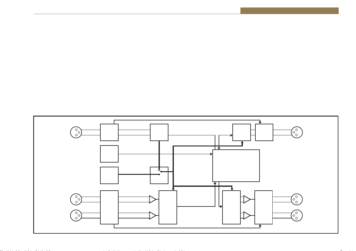
Synchronisers & Delays - RB-PD2 10
potentiometers on the rear panel allow the input gain range to be altered by
±3dB around the selected peak digits.
The analogue output gain range can be altered in software from -6dBu
to +24dBu output level, ref FSD. Both analogue and digital outputs can
be separately muted and a front panel Bypass button disengages electromechanical relays to divert both analogue and digital inputs to their outputs.
This is also disengaged automatically when a power-fail occurs.
The RB-PD2 features a remote port supplying 8 inputs and 6 outputs, all of
which are freely assignable. The inputs can be used to trigger any of the unit’s
functions such as build delay, activate cough or enter record mode and start
a new recording. The outputs can provide external signaling to indicate when
certain events have occurred such as the delay reaching the required value or
System Block Diagram
AES/EBU
Gain
Gain
AES
Receiver
Clock
Select
Recovered
Clock
ADC
Digital
Input
Professional
Balanced
L
R
Analogue
Inputs
Digital
Bypass
Control
Compact
Flash Card
Interface
Master
Clock
Generator
Analogue
Bypass
Control
the outputs being muted. From V1.06 firmware onwards, the RB-PD2 can
delay remote inputs 1-6 to the remote outputs 1-6, so that remote control
commands can also be synchronised with the same delay as the RB-PD2.
Because playback from a Compact Flash™ card can be triggered remotely,
the RB-PD2 can also be used at transmitter sites to play an emergency
audio file via GPI in the event of silence detection.
The front panel controls can be locked out for situations where remote
control is being used to run the unit, or where physical security is required.
Important Note
Certain newer Compact Flash (CF) cards can cause the RB-PD2 to reboot,
reset or ‘hang-up’. This can be resolved by repowering the unit with the CF
card already inserted.
AES/EBU
AES
Transmitter
Source Select & Automatic
Audio Stretch Delay Control
DAC Analogue
Gain
Gain
Digital
Bypass
Control
Bypass
Control
Digital
Output
Professional
Balanced
Analogue
Outputs
L
R
Fig 10-2: RB-PD2 System Block Diagram
61

10 Synchronisers & Delays - RB-PD2
Quickstart Guide
This quick start guide briefly explains the steps required to get the RB-PD2
up and running if you just want to get the unit on-air quickly.
There are 2 different methods of operation for using the RB-PD2. The first
is to use the Audio Stretch algorithms to build up a delay time which can
then be ‘dumped’ in audio segment lengths that you define. The second is
to Play a File from a Compact Flash card which can be inserted into the slot
in the front panel.
For both methods, there are 2 menu options that need to be set prior to
operating the delay: Start Mode and Dump Mode. Start Mode defines how
the RB-PD2 initially builds up the delay period and the Dump Mode defines
what happens when the DUMP/DROP button is pressed. Other options
such as audio source and sample rate are not discussed here as they do not
affect the operation of the unit.
To change options in the main menu, use the SELECT MENU rotary control
to the right of the front panel; press and hold it for 1.5 seconds to enter the
menu, turn the control to highlight the required menu item and press to
select it.
The last item shown in each menu is >CLOSE. Selecting close exits the
system menu and returns to the main display. In each sub-menu, the
penultimate item shown is <BACK. Selecting <BACK displays the previous
menu.
Using the Audio Stretch Method of Operation
1. [MAIN MENU > DELAY OPTIONS > START MODE > BUILD DELAY]. Select
the delay START MODE as BUILD DELAY. BUILD DELAY start mode uses an
audio stretch algorithm to gradually increase the delay from zero to the
selected duration.
2. [MAIN MENU > DELAY OPTIONS > BUILD/EXIT SPEED]. The BUILD/EXIT
SPEED sets the rate at which the audio is altered by the audio stretch
62
algorithm. There are 16 speeds available and each setting shows the
approximate time required to build 10 seconds of delay.
3. [MAIN MENU > DELAY OPTIONS > SAFE PERIOD]. The SAFE PERIOD is a
delay threshold that you can set to define when it is safe for you to use the
DUMP/DROP button. When the current delay is less than the SAFE PERIOD,
the “SECS” label on the main screen flashes. The Safe Period can be set
from 1 to 10 seconds in units of 0.1 seconds.
4. [MAIN MENU > DUMP MODE > DUMP BUFFER]. Select the DUMP MODE
which defines what happens when you press the DUMP/DROP button. The
DUMP BUFFER mode discards the most recently buffered section of audio
when the dump button is pressed so select this.
5. [MAIN MENU > DUMP MODE > BUFFER LENGTH]. Further down the same
DUMP MODE menu, select the BUFFER LENGTH. This option selects the
length of audio dumped from the delay when the DUMP/DROP button is
pressed. It can be set from 1 to 10 seconds in units of 0.1 seconds.
6. If you now select CLOSE and exit out of the menu, you can select the
delay for the Build Delay Start Mode. The Delay Time is set from the main
screen. Briefly press and then turn the SELECT DELAY rotary control to
select a total delay value. Press again to set the value.
The RB-PD2 is now setup for use.
7. To initiate the delay at the start of a programme, press the BUILD DELAY
button. The delay between audio at the inputs and outputs will increase
at the selected build speed until the selected delay is acquired. Whilst
acquiring the delay, the delay time will flash when it is less than the SAFE
PERIOD value. Once the delay has been acquired, it will remain constant.
8. To discard a section of unwanted audio (of a duration defined by the
BUFFER LENGTH) that has already been internally buffered (e.g. a telephone
caller swearing), press the DUMP/DROP button. The presenter should
continue with the programme regardless of the dump mode currently
selected to avoid periods of silence being output.

Synchronisers & Delays - RB-PD2 10
9. To discard a section of unwanted audio that is about to be presented to
the audio inputs (i.e. the presenter coughing), press and hold the COUGH
button for the duration of the unwanted noise. The current delay will count
down whilst the button is held.
10. To discard ALL of the buffered audio and mute the audio outputs, press
and hold the DUMP/DROP button to initiate the DROP function. The audio
outputs will remain muted until the button is released. At this point, if the
unit was exiting the delay prior to the drop function, the delay will remain
at zero. Otherwise BUILD DELAY mode will be initiated.
11. At the end of a programme, press the EXIT DELAY button to begin
ramping the delay to zero.
Using the Play File Method of Operation
1. [MAIN MENU > DELAY OPTIONS > START MODE> PLAY FILE]. Select the
delay START MODE as PLAY FILE. This start mode plays an audio file (linear
PCM) stored on a Compact Flash™ memory card inserted in the front panel
card slot.
2. [MAIN MENU > DELAY OPTIONS > START MODE > SELECT PLAY FILE]. The
SELECT PLAY FILE option is used to choose the pre-recorded .wav file (stored
on the CF card) which will be played out when the delay is first being built
up. Note that the sample rate and bit depth of the RB-PD2 output must be
the same as the recording on the CF card (see page 71: Sample Rate &
Sample Width). Also, you can make a recording directly on the RB-PD2 (see
page 71: Record).
3. [MAIN MENU > DUMP MODE > PLAY FILE]. Select the DUMP MODE which
defines what happens when you press the DUMP/DROP button. The PLAY
FILE mode plays the audio file selected by the SELECT PLAY FILE option
below.
4. [MAIN MENU > DUMP MODE > SELECT PLAY FILE]. The SELECT PLAY FILE
option selects the audio file to be played when the Play File dump mode is
selected. Select the required dump Play File from the list of available files.
5. Select CLOSE and exit out of the menu
The RB-PD2 is now setup for use.
6. To initiate the delay at the start of a programme, press the BUILD DELAY
button and begin your radio programme immediately. When the BUILD
DELAY button is pressed, the selected audio file is played and the unit
immediately begins to buffer the audio presented at the inputs. When the
file has finished playing, the output of the RB-PD2 reverts to the buffered
audio and the length of the delay is equal to the duration of the audio file.
7. To discard a section of unwanted audio that has already been internally
buffered (e.g. a telephone caller swearing), press the DUMP/DROP button.
When the DUMP/DROP button is pressed, all the internally buffered audio
is discarded, the selected audio file is played and the unit immediately
begins to buffer the audio presented at the inputs. When the file has
finished playing, the output of the RB-PD2 reverts to the buffered audio
and the length of the delay is equal to the duration of the audio file. The
presenter should continue with the programme regardless of the dump
mode currently selected to avoid periods of silence being output.
8. To discard a section of unwanted audio that is about to be presented to
the audio inputs (i.e. the presenter coughing), press and hold the COUGH
button for the duration of the unwanted noise. The current delay will count
down whilst the button is held. And once released, the delay will be built up
again using the audio stretch method.
9. To discard ALL of the buffered audio and mute the audio outputs, press
and hold the DUMP/DROP button to initiate the DROP function. The audio
outputs will remain muted until the button is released. At this point, if the
unit was exiting the delay prior to the drop function, the delay will remain
at zero. Otherwise the delay will be built up again using the audio stretch
method.
10. At the end of a programme, press the EXIT DELAY button to begin
ramping the delay to zero.
63

10 Synchronisers & Delays - RB-PD2
Front Panel Controls
All of the RB-PD2’s configurations can be accessed with the single front
panel mounted rotary control in conjunction with the vacuum fluorescent
display.
Fig 10-3: RB-PD2 Rotary Control Operation
Setting the Delay
The target delay of the RB-PD2 is dependent on the selected Start Mode.
There are 2 start modes; Build Delay and Play File.
Build Delay Mode
In Build Delay mode, the delay will be acquired using the automatic audio
stretch algorithm until the target delay has been built up. The rate at which
the delay is built up depends on the current audio stretch algorithm speed
setting.
To adjust the delay, lightly press the rotary control to enable the delay
edit mode. The decimal point on the selected delay value on the left
hand side of the main screen will flash to indicate that delay edit mode
has been entered. The value of the delay can now be changed by turning
the rotary control. Once the required delay value has been set, press the
rotary control again to return to normal operation. The delay edit mode is
automatically cancelled if no change is made to the delay within a period of
2.5 seconds.
If the current delay is not zero, i.e. a certain amount of delay has already
built up, changes to the delay are implemented dynamically. For example, if
the current delay is 7.0 seconds and a new delay of 5.5 seconds is selected,
the delay will automatically decrease to the new value and the status line
will show “DECREASING DELAY”.
Play File Mode
In Play File mode, an audio file stored on a Compact Flash™ memory card
is played whilst simultaneously buffering the audio at the selected audio
input source. Once the audio file has finished playing, the buffered audio is
output and the delay is set to the duration of the file just played.
In this start mode, the selected delay value on the left hand side of the
main screen shows the length of the selected start play file. The selected
delay cannot be edited until the start file has finished playing.
The BUILD DELAY Button
The BUILD DELAY button activates the build delay mode when the audio
stretch algorithm starts to silently build up audio delay. This mode can
only be entered if the unit is at zero delay or in exit delay mode. The audio
stretch algorithm builds the delay based on the current build/exit speed
(the Delay Build/Exit Speed – see page 69).
The actual operation will depend on the current delay and the currently
selected start mode. If the current delay is zero, the delay will build using
the selected start mode. However, if the current delay is greater than zero
i.e. some delay has already been acquired, the automatic audio stretch
algorithm is activated to build the delay to the selected value.
The BUILD DELAY button is illuminated red whilst the delay is being
acquired and the status line on the display will show either “PLAYING DELAY
START FILE” or “BUILDING DELAY” depending on which build mode is active.
Once the delay reaches the pre-selected value, the BUILD DELAY button is
illuminated green and the status line shows “DELAY OK”.
64

Synchronisers & Delays - RB-PD2 10
The EXIT DELAY Button
The EXIT DELAY button activates the exit delay mode when the audio delay
is reduced to zero. The delay ramps down at the rate specified by the
current build/exit speed (the Delay Build/Exit Speed – see page 69).
Fig 10-4: RB-PD2 Front Panel Buttons
This mode can only be activated if the unit is currently in build delay mode
or is at the currently selected delay (shown via the status line on the
display).
The EXIT DELAY button is illuminated red whilst the delay is being reduced
and the status line will show “EXITING DELAY”. Once the delay has been
reduced to zero, the EXIT DELAY button will illuminate green for 1.5 seconds
and the status line on the display will show “ZERO DELAY”.
The COUGH Button
The COUGH button activates the cough function which allows unwanted
audio that is about to be presented to the audio inputs to be discarded. The
cough function is only active whilst the COUGH button is pressed.
The COUGH button is illuminated red and the status line on the display will
show “COUGH ACTIVE”. The current delay shown on the display will count
down whilst the button is pressed. If the COUGH button continues to be
pressed and the current delay counts down to 0, the audio outputs will be
muted until the COUGH button is released.
When the unwanted noise has passed, the COUGH button can be released
and the status line will indicate the current state. If the exit delay mode
was active prior to the cough function, the status line will show “EXITING
DELAY” unless the delay has reached 0, in which case the status line will
show “ZERO DELAY”. Otherwise the build delay mode will re-engage and
status line will show “BUILDING DELAY”.
The Audio BYPASS Button
The BYPASS button enables the delay bypass mode, which internally
connects the inputs to outputs in both the analogue and digital domains.
The BYPASS button is illuminated red when the delay bypass mode is
enabled and the analogue and digital icons on the display will change
to
. When power is removed from the unit, the bypass mode is
automatically enabled.
The DUMP/DROP Button
Pressing the DUMP/DROP button activates the currently selected dump
mode. The dump mode can be initiated at any time provided the current
delay is not at 0. The button is illuminated red and the status line displays
“DUMP ACTIVE”. With the dump buffer mode selected, a pre-selected
length (the Dump Buffer Length - see page 70) of most recent audio data
is discarded from the internal audio buffer each time the dump button is
pressed. If the current delay is less than the dump buffer length, the delay
is set to 0. When the dump buffer function has completed, the delay will
automatically start to build unless the exit delay mode was active prior to
the dump being activated.
When the dump mode is set to play file, all the buffered audio is discarded
and the selected audio file on the Compact Flash™ memory card is played.
Audio is immediately buffered to create a new delay which will be equal
to the duration of the audio file being played. When the file has finished
playing the status display will show “DELAY OK”.
65
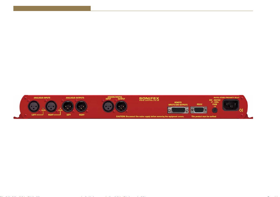
10 Synchronisers & Delays - RB-PD2
Pressing and holding the DUMP/DROP button for 0.8 seconds, activates the
DROP function. All of the currently acquired delay is discarded, the audio
outputs are muted and the status display will show “DROP ACTIVE”. When
the DUMP/DROP button is released, its illumination is turned off, the audio
outputs are un-muted and the status line indicates the current mode. If the
exit delay mode was active prior to the drop function, the status line will
show “ZERO DELAY”. Otherwise the build delay mode will re-engage and
status line will show “BUILDING DELAY”.
System Reset
A single LED on the left side of the front panel indicates that power is
applied. The system reset button is accessible through the small aperture to
the right of the power LED.
Rear Panel Connections
Fig 10-5: RB-PD2 Rear Panel
Selecting the Main Menu
The RB-PD2’s configuration options are accessed from the main system
menu. To access the main system menu, press and hold the rotary control
for at least 1.5 seconds. The menu structure is arranged in a multi-tiered
format with several menu items providing access to sub-menus. To select
a menu item, turn the rotary control until the required item is highlighted,
then press the rotary control to select the item. Each configuration is shown
as a list of available options. The currently selected option will be shown
with a tick along side it. The last item shown in each menu is >CLOSE.
Selecting close exits the system menu and returns to the main display.
In each sub-menu, the penultimate item shown is <BACK. Selecting back
displays the previous menu.
66

Synchronisers & Delays - RB-PD2 10
XLR Analogue Inputs (Left and Right)
The XLR 3 pin sockets used for the left and right channel analogue inputs
ĂƌĞĞůĞĐƚƌŽŶŝĐĂůůLJďĂůĂŶĐĞĚĂŶĚŚĂǀĞĂŶŝŵƉĞĚĂŶĐĞŐƌĞĂƚĞƌƚŚĂŶϭϬŬё
bridging. Each XLR has the following connections:
Pin 1: Screen
Pin 2: Phase
Pin 3: Non-phase
Analogue Input Adjustment
The Input Peak Digits setting (see System Menu: Volume) sets the
analogue input gain for full-scale digits in the digital domain. The preset
potentiometers next to the analogue inputs allow an additional adjustment
of this value by ±3dB.
AES/EBU Input
dŚĞĚŝŐŝƚĂůŝŶƉƵƚy>ZϯƉŝŶƐŽĐŬĞƚŚĂƐĂŶŝŵƉĞĚĂŶĐĞŽĨϭϭϬё/ƚŚĂƐƚŚĞ
following connections:
Pin 1: Screen
Pin 2: Phase
Pin 3: Non-phase
The signals on this connector should meet the IEC 60968 specification.
XLR Analogue Outputs (Left and Right)
The XLR 3 pin output plugs are electronically balanced with an output
impedance of less
ƚŚĂŶϱϬёdŚĞLJŚĂǀĞƚŚĞĨŽůůŽǁŝŶŐĐŽŶŶĞĐƚŝŽŶƐ
Pin 1: Screen
Pin 2: Phase
Pin 3: Non-phase
AES/EBU Output
dŚĞĚŝŐŝƚĂůŽƵƚƉƵƚy>ZϯƉŝŶƉůƵŐŚĂƐĂŶŝŵƉĞĚĂŶĐĞŽĨϭϭϬё/ƚŚĂƐƚŚĞ
following connections:
Pin 1: Screen
Pin 2: Phase
Pin 3: Non-phase
The signals on this connector comply with the IEC 60968 specification.
Remote Inputs and Outputs
The 15-way ‘D’ type socket connector presents 8 active low inputs and 6
open collector outputs which can be programmed to your requirements.
The inputs are used to remotely activate a pre-assigned function andthe
outputs provide an indication that a pre-assigned state is currently active
(see System Menu: Remotes).
The remote outputs 1-6 can also be optionally be made to follow the inputs
1-6 with the current programme delay inserted between actuation on the
input and actuation on the output. This can be useful for timed events that
need to account for the delay built up by the RB-PD2.
It has the following connections:
Pin 1: Active low input 1
Pin 2: Active low input 2
Pin 3: Active low input 3
Pin 4: Active low input 4
Pin 5: Active low input 5
Pin 6: Active low input 6
Pin 7: Active low input 7
Pin 8: Active low input 8
Pin 9: Signal ground
Pin10: Open collector output 1
Pin11: Open collector output 2
Pin12: Open collector output 3
Pin13: Open collector output 4
Pin14: Open collector output 5
Pin15: Open collector output 6
67

10 Synchronisers & Delays - RB-PD2
RS232
The 9-way ‘D’ type socket connector allows direct connection to a serial
port on a PC via a pin-to-pin cable. See the section on Serial Port Control for
details of this interface. It has the following connections:
Pin 1: N/C
Pin 2: Transmit data (TxD)
Pin 3: Receive data (RxD)
Pin 4: N/C
Pin 5: Ground
Pin 6: N/C
Pin 7: Clear To Send (CTS)
Pin 8: Request To Send (RTS)
Pin 9: N/C
The Default Screen
ANALOGUE
48KHZ 16BIT
✓
A A D
DELAY:
06.0 SECS
00.0
SECS
ZERO DELAY
Fig 10-6: The Default Screen
The default screen shows the current selections for audio source, sample
rate and sample bit width in the top left of the screen. The selected
delay value is shown on the left while the current delay is shown in larger
characters on the right. The “SECS” label shown next to the current delay
will flash if the current delay is below the SAFE PERIOD.
The current status of the unit is displayed on the status line at the bottom
of the screen. Also shown on the main screen is the mute status of the
analogue and digital outputs, and the status of the Compact Flash™
memory card, if fitted. When a memory card is fitted, a small memory card
symbol will appear above the analogue and digital audio output status
icons. A tick next to the memory card symbol indicates the card is ready for
use, whereas a cross indicates that there is an error.
All of the RB-PD2’s settings are configured from the main system menu with
the exception of the selected delay. The delay is adjusted directly from the
main screen following the instructions on page 64.
The Main Menu
MAIN MENU
SYSTEM MODE
DELAY OPTIONS
DUMP MODE
SOURCE
SAMPLE RATE
SAMPLE WIDTH
RECORD
VOLUME
MEMORY CARD
REMOTES
CONTROL LOCK
SYSTEM
CLOSE
Fig 10-7: The Main Menu Screen
To access the main menu, press and hold the rotary control knob for 1.5
seconds. Instructions for navigating the menu structure are on page 66.
The available menu and sub menu items are described below together with
the associated configuration options.
68

Synchronisers & Delays - RB-PD2 10
SYSTEM MODE
This selection shows the SYSTEM MODE sub-menu. The sub-menu items are
NORMAL MODE and REVIEW MODE.
Normal Mode
This option selects the normal profanity delay operating mode of the unit.
This is the default mode.
Review Mode
This option selects the review mode. This mode allows constant live
monitoring of an audio feed, with the ability to repeat sections of audio by
increasing the delay by a preconfigured step. See the Review Mode section
for details.
DELAY OPTIONS
This selection shows the DELAY OPTIONS sub-menu. The sub-menu items
are START MODE, BUILD/EXIT SPEED and SAFE PERIOD.
START MODE
This option defines how the delay is built-up. From the DELAY OPTIONS submenu select START MODE. The available options are BUILD DELAY, PLAY FILE
and SELECT PLAY FILE.
• Build Delay – With this option selected, the delay is built up using the
automatic audio stretch algorithm. The length of the delay is selected via
the main screen.
• Play File – With this option selected, the delay is built up whilst playing a
pre-selected audio file on a Compact Flash™ memory card. The length of
the delay will be equal to the duration of the selected audio file.
• Select Play File – This option selects the audio file to be played when
the Play File start mode is selected. It shows all available audio files
on the Compact Flash™ memory card which match the current audio
configuration settings (sample rate and sample width). If the card has
sub-directories defined, these are also shown. To select a file, turn the
rotary control and then press when the required file is highlighted. To
move to a sub-directory, press the rotary control with the highlight over
the required directory name. Whilst viewing a sub-directory, the top item
in the list is UP which, when selected, returns to the parent directory.
The default start mode is Build Delay.
BUILD/EXIT SPEED
This option selects the rate at which the audio stretch algorithm builds and
exits the delay. There are 16 speed settings and each is shown with the
approximate time required to build/exit a 10 second delay. These settings
are 5mins 30secs, 5mins 00secs, 4mins 30secs, 4mins 00secs, 3mins 30secs,
3mins 00secs, 2mins 30secs, 2mins 20secs, 2mins 10secs, 2mins 00secs,
1min 50secs, 1min 40secs, 1min 30secs, 1min 20secs, 1min 10secs and
1min 00secs. When building from zero delay, the audio stretch algorithm is
designed to start at a slow speed and increase to the configured speed. This
helps to avoid sudden tempo changes. Likewise, when exiting the delay and
as the current delay approaches zero, the speed is decreased. Consequently,
the times shown for each speed setting will be slightly less for subsequent
10 seconds periods. For example, if the delay is set to 20 seconds, and the
speed selected is 3mins 00secs, the first 10 seconds of delay will be acquired
in the time specified, while the remaining 10 seconds will take slightly less
time. The build/exit speed can only be changed when the current delay is
zero. The default build/exit speed is 2mins 30secs.
SAFE PERIOD
This option selects the safe period duration, i.e., amount of delay that needs
to be built up before the DUMP button can be used without muting the
outputs. To edit the safe period, turn the rotary control until the highlight is
over the safe period value. Press the rotary control to enter edit mode. The
highlight changes to a flashing line under the current value. Now turn the
rotary control to select a new safe period between 1 and 10 seconds in units
of 0.1 seconds. When the required value is shown, press the rotary control
again to leave edit mode. Now turn the rotary control to select either OK
which saves the new value, or CANCEL which discards the changes.
69

10 Synchronisers & Delays - RB-PD2
The “SECS” label on the right hand side of the main screen, next to the
current delay value, flashes when the current delay is less than the safe
period. If the safe period is set to the same duration as the dump length, it
provides a quick visual indication of when the dump can be used without
the outputs muting, as would be the case if the dump period is longer than
the current delay.
The default safe period is 2.0 seconds.
DUMP MODE
This option selects the mode of operation when the DUMP button is
pressed. From the main system menu select DUMP MODE. The available
options are DUMP BUFFER, PLAY FILE, BUFFER LENGTH and SELECT PLAY
FILE.
• Dump Buffer – This option discards a pre-selected amount of audio from
the internal delay buffer. For example, if the current delay is 10 seconds
and the dump buffer length is 4 seconds, when the dump is activated,
the position at which the audio at the selected input is stored in the
internal memory buffer is moved back by 4 seconds. This effectively
overwrites the last four seconds of audio and the delay will be reduced
to 6 seconds. The audio stretch algorithm will automatically activate after
the dump to return the delay to the selected duration.
• Play File – This option plays a pre-selected audio file on a Compact
Flash™ memory card and discards all of the currently buffered audio.
Delay acquisition begins again immediately and the new delay length is
equal to the duration of the file played.
• Buffer Length – This option selects the dump buffer length when the
Dump Mode is set to Dump Buffer. To edit the buffer length, turn the
rotary control until the highlight is over the dump buffer value. Press the
rotary control to enter edit mode. The highlight changes to a flashing
line under the current value. Now turn the rotary control to select a new
dump buffer length between 1 and 10 seconds in units of 0.1 seconds.
When the required value is shown, press the rotary control again to leave
edit mode. Now turn the rotary control to select either OK which saves the
new value, or CANCEL which discards the changes.
• Select Play File – This option selects the audio file to be played when
the Play File dump mode is selected. It shows all available audio files
on the Compact Flash™ memory card which match the current audio
configuration settings (sample rate and sample width). If the card has subdirectories defined, these are also shown. To select a file, turn the rotary
control and then press when the required file is highlighted. To move to a
sub-directory, press the rotary control with the highlight over the required
directory name. Whilst viewing a sub-directory, the top item in the list is
UP which, when selected, returns to the parent directory.
• The default dump mode is dump buffer with a buffer length of 2.0 seconds.
SOURCE
This option selects which input is used for the audio delay process. From the
main system menu select SOURCE. The available options are ANALOGUE,
ANALOGUE SYNC and DIGITAL. The delayed audio appears at both the
analogue and digital outputs regardless of the input source selected.
• Analogue – This selects the audio at the analogue inputs as the source for
the delay. The input is sampled and delayed using the selected sample rate
generated from an internal master clock. The digital input is not used.
• Analogue Sync – This selects the audio at the analogue inputs as the
source for the delay. The input is synchronized to the digital audio sync
signal at the digital input and the analogue and digital audio outputs will
be muted until a valid sync signal is detected. Once a valid sync signal has
been received, audio will appear at the outputs and the delay can then be
started. Any subsequent loss of sync signal will force the unit to revert to
an internally generated master clock rate as near as possible to the last
sync signal received.
• Digital – This selects the audio at the digital input as the source for the
delay. With no digital signal applied, the analogue and digital audio
outputs will be muted. Once a valid digital input is received, the unit locks
70

Synchronisers & Delays - RB-PD2 10
to this signal and audio will appear at the outputs. The analogue inputs
are not used.
• The default source is analogue.
SAMPLE RATE
This option selects the sample rate used when the input source is set to
Analogue. From the main system menu select SAMPLE RATE. The available
options are 32kHz, 44.1kHz and 48kHz. The sample rate can only be
changed when the current delay is zero. The default sample rate is 48kHz.
SAMPLE WIDTH
This option selects the sample size used in the analogue to digital and
digital to analogue conversion. From the main system menu select SAMPLE
WIDTH. The available options are 16BIT and 24BIT. The sample width can
only be changed when the current delay is zero. The default sample width
is 24bits.
RECORD
This selection shows the Record sub-menu which allows you to make a
recording onto a CF card. Note that pre-recorded .wav files can also be
played by selecting DUMP MODE>Select Play File.
The sub-menu items are NEW RECORDING, SOURCE, SAMPLE RATE, SAMPLE
WIDTH and INITIALS.
New Recording
L
R
DURATION:
00:00:00
REC
FILENAME: RECD0001.WAV
FORMAT: AN 48KHZ 24BIT
Fig 10-8: The Record Screen
This option enters the record screen provided a valid Compact Flash™
memory card is inserted in the front panel Compact Flash™ memory card
slot. An error message will be displayed if no memory card is present,
or a new record audio file cannot be initialized, or the maximum number
of recordings already exists in the current directory, or insufficient space
exists.
The record screen shows the filename that the audio will be recorded to
as well as the record parameters that are currently set. The PPM display at
the top of the record screen gives a visual indication of the audio levels for
the selected source with the line on the scale indicating the 0dB point. In
record mode, the DUMP/DROP button doubles as a control for the record
process. To start recording, press the button once. The button illuminates,
the record pause icon is cleared and the recording starts with the on-screen
duration indicating the length of the recording. To stop the recording, press
the DUMP/DROP button again. The new audio file is saved, the record mode
is exited and the main default screen is displayed.
To exit the record screen prior to starting record, press and hold the rotary
control for 1.5 seconds. Position the highlight over EXIT RECORD and press
the rotary control.
Source
This option selects which input is used for the record process. From the
record sub-menu select SOURCE. The available options are ANALOGUE,
ANALOGUE SYNC and DIGITAL.
The analogue and digital outputs are muted whilst in record mode.
• Analogue – This selects the audio at the analogue inputs as the source
for recording. The input is sampled using the selected record sample rate
generated from an internal master clock. The digital input is not used.
• Analogue Sync – This selects the audio at the analogue inputs as the
source for recording. The input is synchronized to the digital audio sync
signal at the digital input.
71

10 Synchronisers & Delays - RB-PD2
• Digital – This selects the audio at the digital input as the source for
recording. The analogue inputs are not used. The default record source
is analogue.
Sample Rate
This option selects the sample rate used for recording when the input
source is set to Analogue. From the record sub-menu select SAMPLE RATE.
The available options are 32kHz, 44.1kHz and 48kHz. The default record
sample rate is 48kHz.
Sample Width
This option selects the sample size used for recording in the analogue to
digital conversion. From the record sub-menu select SAMPLE WIDTH. The
available options are 16BIT and 24BIT. The default record sample width is
24bits.
Initials
This option sets the first 4 characters of the record filename that is
automatically generated when entering record. The filename consists
of these 4 characters followed by a 4 digit number which automatically
increments as new recordings are made. The file extension for all recordings
is “WAV”. For example, with the initials set to “RECD”, the first record
filename will be “RECD0001.WAV”.
To set the initials, turn the rotary control to highlight a character and then
press the rotary control to enter edit mode. The highlight changes to a
flashing line under the selected character. Now turn the rotary control
to select a new character in that position. When the required character
is shown, press and turn the rotary control to select a new edit position.
When the required changes have been made, select either OK to save the
new initials, or CANCEL to discard the changes. The default initials are
“RECD”.
72
VOLUME
This selection shows the Volume sub-menu where you can set input and
output gains and also mute the outputs. The sub-menu items are INPUT PK
DIGITS, OUTPUT GAIN, ANALOGUE MUTE and DIGITAL MUTE.
Input Peak Digits
This option sets the full-scale dB input amplitude that will give full-scale
digits in the
digital domain. From the VOLUME sub-menu select INPUT PK DIGITS. The
available options are +12 dB, +18 dB and +24 dB. The default value for input
peak digits is +12dB.
Output Gain
This option sets the gain of the analogue output stage. From the VOLUME
sub-menu select OUTPUT GAIN. The available gain settings are from –6 dB
to +24 dB in 1 dB increments. The default value for output gain is +12dB.
Analogue Mute
This option mutes the analogue audio output. From the VOLUME sub-menu
select ANALOGUE MUTE. The available options are OFF and ON and by
default, the analogue
mute is off. This option can be remotely controlled.
Digital Mute
This option mutes the digital audio output. From the VOLUME sub-menu
select DIGITAL MUTE. The available options are OFF and ON and by default,
the digital mute is off. This option can be remotely controlled.
MEMORY CARD
This selection shows the Memory Card sub-menu. The sub-menu items are
DETAILS, FILE DELETE and FORMAT CARD. A Compact Flash™ memory card
slot, accessible from the front panel, accepts memory cards up to 2Gbytes.
Details
This selection shows details of the memory card currently inserted into the
Compact Flash™ memory card slot. From the MEMORY CARD sub-menu

Synchronisers & Delays - RB-PD2 10
select DETAILS. The information shown is the model number and the size of
the card in Mbytes.
File Delete
This option allows any of the files on the Compact Flash™ memory card to
be deleted. From the memory card sub-menu select FILE DELETE. The files
and sub-directories on the Compact Flash™ memory card are shown in a
list with the sub-directories at the top. Turn and press the rotary control to
highlight and select the file to delete. A confirmation message box will be
displayed; select OK to delete the file or select CANCEL to return to the list.
To move to a sub-directory, press the rotary control with the highlight over
the required directory name. Whilst viewing a sub-directory, the top item in
the list is UP which, when selected, returns to the parent directory.
Format Card
This formats the CF card using a 16-bit FAT DOS format. From the MEMORY
CARD sub-menu select FORMAT. When Format Card is selected, the system
menu is exited, the main screen is shown & a message box is indicates that
the memory card is being formatted.
Please note: Formatting will delete all files and directories on the memory
card.
REMOTES
This selection shows the Remotes sub-menu and allows you to configure
the remote inputs and outputs to control the RB-PD2 externally. The
sub-menu items are VIEW SETTINGS, CONFIGURE INPUTS and CONFIGURE
OUTPUTS.
View Settings
This selection lists the current settings for the 8 remote inputs and the 6
remote outputs. From the REMOTES sub-menu select VIEW SETTINGS.
Configure Inputs
This selection sets the function that will be activated by the corresponding
remote input. From the REMOTES sub-menu select CONFIGURE INPUTS
followed by the required input number. A list is shown displaying all the
possible functions that can be activated by the remote input with the
default being NO ACTION:
NO ACTION
BUILD DELAY
EXIT DELAY
BUILD/EXIT DELAY (toggles the mode between build and exit delay)
ACTIVATE DUMP
ACTIVATE DROP
ACTIVATE COUGH
START RECORDING
MUTE OUTPUTS (both analogue and digital) and
ACTIVATE BYPASS
DELAY TO OUTPUT.
The options for remote input 7 and 8 remain unchanged.
If a remote input is set to “Delay To Output”, the corresponding remote
output in the remote output configuration options (Main Menu->Remotes>Configure Outputs->Output 1-6) is inaccessible and a message box is
displayed stating that this remote output is controlled by the corresponding
input.
For remote inputs that are configured as “Delay To Output”, an active
remote input (shorted to 0V) produces an active open collector output on
the corresponding remote output after the current delay time period has
elapsed. The open collector output is
de-activated after the current delay period when the remote input is deactivated.
Configure Outputs
This selection sets the remote output signaling options for the
corresponding remote output. From the REMOTES sub-menu select
CONFIGURE OUTPUTS followed by the required output number. Each
remote output can signal when a certain function or state has been
73

10 Synchronisers & Delays - RB-PD2
activated. A list is shown displaying all the possible states that can be
signaled
by the remote output, with the default being NO ACTION:
NO ACTION
ZERO DELAY
BUILDING DELAY
DELAY SAFE (current delay is greater than safe period)
DELAY OK
EXITING DELAY
DUMP ACTIVE
DROP ACTIVE
COUGH ACTIVE
RECORD ACTIVE
OUTPUTS MUTED and
BYPASS ACTIVE.
CONTROL LOCK
This option allows the front panel bypass and rotary controls to be disabled.
From the main system menu select CONTROL LOCK. The available options
are OFF and ON. Access to the system menu is still enabled when the
control lock is on to allow the lock to be removed. When the control lock
is enabled, a small key icon is displayed in the upper right side of the main
screen display. By default, the control lock is off.
SYSTEM
This selection shows the System sub-menu. The sub-menu items are BAUD
RATE and INFORMATION.
Baud Rate
This selection allows the baud rate of the serial port to be set. From the
SYSTEM sub-menu select BAUD RATE. The available options are 9600,
19200, 38400, 57600 and 115200. The default baud rate is 19200.
74
Information
This selection shows product and software version information. From the
SYSTEM sub-menu select INFORMATION.
The Product Id is set to RB-PD2. This is used to identify the unit when using a
PC and the Sonifex SCi control software.
The Serial Number is factory set. Always quote this number in any
correspondence with Sonifex technical support.
The Bootstrap Version Number is the revision of the software that boots the
system and controls the firmware upgrade process. This software is installed
at the factory and can only be upgraded by Sonifex.
The Version Number is the revision of the main software. This software can
be upgraded. For the latest software updates, check the Sonifex website at
www.sonifex.co.uk
The Display Version Number is the software revision running on the display
PCB.
Review Mode
Review mode changes the functionality of the unit. It allows live monitoring
of an audio input with the ability t
the delay immediately by a preconfigured step. The delay can be increased
multiple times until either the maximum possible delay is reached or no
further delays increases by the preconfigured step are possible. Review
mode is enabled via: [MAIN MENU > SYSTEM MODE > REVIEW MODE].
The default screen shows the selected step size in seconds on the left hand
side of the display and the current delay in a larger font on the right hand
side. The current status is shown at the bottom of the display, and shows
“MONITORING LIVE” when the output is not delayed, and “REVIEW ACTIVE”
when the delay is active.
The step size is changed directly from the main screen. Briefly press the
rotary control to enable the step edit mode. The decimal point on the
o repeat sections of audio by increasing

Synchronisers & Delays - RB-PD2 10
current step value on the left hand side of the screen will flash to indicate
that step edit mode has been entered. The value of the step can now be
changed by turning the rotary control. Once the required value has been
set, press the rotary control again to return to normal operation. The step
edit mode is automatically cancelled if no change is made to the step within
a period of 2.5 seconds.
Pressing the DUMP button increases the delay by the current step size.
When the delay is active, the EXIT DELAY button illumination is turned
off, and the DUMP button illumination is turned on. When no more delay
increases are available at the current step size, the DUMP button will flash.
The maximum delays for the indicated sample rates are shown below:
32 kHz sample rate - 55.2 seconds for 16 bit, 27.6 seconds for 24 bit
44.1 kHz sample rate - 40.0 seconds for 16 bit, 20.0 seconds for 24 bit
48 kHz sample rate - 36.8 seconds for 16 bit, 18.4 seconds for 24 bit
To return to live monitoring, press the exit delay button. The DUMP button
illumination is turned off and the EXIT button illumination is turned on.
The current delay can be temporarily bypassed by pressing the BYPASS
button. This allows the live audio to be temporarily monitored while the
delay is still active. Both the DUMP and EXIT DELAY buttons are still active
while the bypass is active.
The BUILD DELAY and COUGH buttons are disabled when the review mode
is selected and the menu options DELAY OPTIONS, DUMP MODE, SOURCE,
RECORD, MEMORY CARD and REMOTES are omitted as they do not apply.
The source selection is pre-set to Analogue in review mode.
Serial Port Control
The Serial Port allows the RB-PD2 to be controlled and updated from a
PC using the Sonifex Serial Control Interface (SCI) software. This software
is available as a free download from the Sonifex website at www.sonifex.
co.uk/sci.
Default Settings for the Serial Port
Baud Rate: 19200
Data Bits: 8
Stop Bits: 1
Parity: Even
Handshaking: None
Serial Interface Commands and Responses
Most of the commands follow the same structure: a 3 letter command
followed by a colon, followed by a parameter (if any) and terminated by
Carriage Return with optional Line Feed. A Line Feed character may be sent
but it will be ignored by the RB-PD2. Commands are not case sensitive.
Responses will be CR & LF terminated.
After the profanity delay has been powered-up, an initialisation string is
sent
“Initialising PD2”.
Following are the commands and the expected responses:
Command Description Response
Bnn: **Set baud rate where: ACK: or NAK: (at old rate)
nn = 11 (115200 baud)
nn = 57 (57600 baud)
nn = 38 (38400 baud)
nn = 19 (19200 baud)
nn = 96 (9600 baud)
BPD: Bypass disable ACK: or NAK:
BPE: Bypass enable ACK: or NAK:
BSV: **Bootstrap version request BSV:Vn.n
where n.n = bootstrap version
CST: Cough start ACK: or NAK:
75

10 Synchronisers & Delays - RB-PD2
CSP: Cough stop ACK: or NAK:
DLB: Build delay ACK: or NAK:
DLC: Clear delay immediately to zero ACK:
DLE: Exit delay ACK: or NAK:
DLF:c Delete file on Compact ACK: or NAK:
Flash™ memory card where:
c = “\path\filename”
(c=“\filename” for files in root directory)
DLY:n Set required delay where: ACK: or NAK:
n = delay in milliseconds (100ms resolution)
DRO: Drop start ACK: or NAK:
DRS: Drop stop ACK: or NAK:
DSP:n Set delay build/exit speed where: ACK: or NAK:
n = 0 (5mins 30secs)
n = 1 (5mins 00secs)
n = 2 (4mins 30secs)
n = 3 (4mins 00secs)
n = 4 (3mins 30secs)
n = 5 (3mins 00secs)
n = 6 (2mins 30secs)
n = 7 (2mins 20secs)
n = 8 (2mins 10secs)
n = 9 (2mins 00secs)
n = 10 (1min 50secs)
n = 11 (1min 40secs)
n = 12 (1min 30secs)
n = 13 (1min 20secs)
n = 14 (1min 10secs)
n = 15 (1min 00secs)
DST: Dump start ACK: or NAK:
DWN: **Download firmware. ACK: or NAK:
New firmware installed
when ‘S-Record’ (ACK: indicates download
terminator received can start)
FMC: Format memory card ACK: or NAK:
GDL:c Get directory list where: GDL:z
76
c = “\path” for base directory
of list (c=“\” for root directory)
z = comma separated list of directories
GFL:n_c Get file list where: GFL:z
n = 1 (list wav files)
n = 2 (list wav files with same
settings as current configuration)
n = 3 (list all files)
c = “\path” for base directory of list
(c=“\” for root directory)
z = comma separated list of files
LOC: Enable control lock ACK: or NAK:
MCD: Request memory card
details where: MCD:y,z or NAK:
y = model number
z = capacity in MBytes
NRC: Initialise new recording ACK: or NAK:
REC:n Record control where: ACK: or NAK:
n = 1 (start)
n = 0 (stop)
RIN:c Set record initials where: ACK: or NAK:
c = 4 character initials
RSC:n Set record source where: ACK: or NAK:
n = 0 (analogue)
n = 1 (analogue sync)
n = 2 (digital)
RSR:n Set record sample rate where: ACK: or NAK:
n = 0 (32 kHz)
n = 1 (44.1 kHz)
n = 2 (48 kHz)
RSW:n Set record sample width where: ACK: or NAK:
n = 0 (16 bit)
n = 1 (24 bit)
SAM:n Set analogue mute where: ACK: or NAK:
n = 0 (off )
n = 1 (on)
SDB:n Set dump buffer length where: ACK: or NAK:

Synchronisers & Delays - RB-PD2 10
n = dump length in milliseconds
(100ms resolution)
SDF:c Set dump play file where: ACK: or NAK:z
c = “\path\filename” (c=“\filename” for files
in root directory)
z = error message
SER: **Serial number request where: SER:z
z = serial number (6 digits)
SDM:n Set digital mute where: ACK: or NAK:
n = 0 (off )
n = 1 (on)
SIP:n Set input peak digits where: ACK: or NAK:
n = 0 (+12dB)
n = 1 (+18dB)
n = 2 (+24dB)
SMD:n Set dump mode where: ACK: or NAK:
n = 0 (dump buffer)
n = 1 (play file)
SMS:n Set start delay mode where: ACK: or NAK:z
n = 0 (build using audio stretch algorithm)
n = 1 (play file)
z = error message
SOG:n Set output gain where: ACK: or NAK:
n = 0 (-6dB)
n = 1 (-5dB)
n = 2 (-4dB)
n = 3 (-3dB)
n = 4 (-2dB)
n = 5 (-1dB)
n = 6 (-0dB)
n = 7 (+1dB)
n = 8 (+2dB)
n = 9 (+3dB)
n = 10 (+4dB)
n = 11 (+5dB)
n = 12 (+6dB)
n = 13 (+7dB)
n = 14 (+8dB)
n = 15 (+9dB)
n = 16 (+10dB)
n = 17 (+11dB)
n = 18 (+12dB)
n = 19 (+13dB)
n = 20 (+14dB)
n = 21 (+15dB)
n = 22 (+16dB)
n = 23 (+17dB)
n = 24 (+18dB)
n = 25 (+19dB)
n = 26 (+20dB)
n = 27 (+21dB)
n = 28 (+22dB)
n = 29 (+23dB)
n = 30 (+24dB)
SRI:i_n Set function for remote
input where: ACK: or NAK:
i = remote input id (0-7)
n = 0 (no action)
n = 1 (build delay)
n = 2 (exit delay)
n = 3 (activate dump)
n = 4 (activate drop)
n = 5 (activate cough)
n = 6 (start new recording)
n = 7 (mute all audio outputs)
n = 8 (activate audio bypass)
SRO:o_n Set function signal for remote
output where: ACK: or NAK:
o = remote output id (0-5)
n = 0 (no action)
n = 1 (delay is at zero)
n = 2 (delay building)
n = 3 (delay is greater than safe period)
n = 4 (delay is at selected value)
n = 5 (delay exiting)
n = 6 (dump active)
n = 7 (drop active)
n = 8 (cough active)
77

10 Synchronisers & Delays - RB-PD2
n = 9 (record active)
n = 10 (audio outputs muted)
n = 11 (audio bypass active)
SRQ:n Status request where: STA:e_f_g_h_i_j_k_l_m_n
e = unit status (8 hex digits) _o_p_q_r_s_t_u_v_w_x_y_z
f = current delay (8 hex digits)
g = selected delay (8 hex digits)
h = start mode setting
i = start play filename
j = safe period setting
k = dump mode setting
l = dump buffer length setting
m = dump play filename
n = source setting
o = sample rate setting
p = sample width setting
q = record source setting
r = record sample rate setting
s = record sample width setting
t = input peak digits setting
u = output gain setting
v = analogue mute status
w = digital mute status
x = bypass status
y = control lock status
z = delay build/exit speed setting
SSC:n Set source where: ACK: or NAK:
n = 0 (analogue)
n = 1 (analogue sync)
n = 2 (digital)
SSF:c Set delay start play file where: ACK: or NAK:z
c = “\path\filename”
(c=“\filename” for files in root directory)
z = error message
SSP:n Set safe period length where: ACK: or NAK:
n = dump length in
milliseconds (100ms resolution)
SSR:n Set sample rate where: ACK: or NAK:
n = 0 (32 kHz)
78
n = 1 (44.1 kHz)
n = 2 (48 kHz)
SSW:n Set sample width where: ACK: or NAK:
n = 0 (16bit)
n = 1 (24bit)
UID: **Unit ID request UID:PD2
UNL: Disable control lock ACK: or NAK:
VER: Version request where VER:Vy.yyy,Vzzzz
y.yyy = firmware version
zzzz = display version
VRS: Request remote VRS:m_n_o_p_q_r_s_t_u_v
settings where: _w_x_y_z
m = remote input 1 setting
n = remote input 2 setting
o = remote input 3 setting
p = remote input 4 setting
q = remote input 5 setting
r = remote input 6 setting
s = remote input 7 setting
t = remote input 8 setting
u = remote output 1 setting
v = remote output 2 setting
w = remote output 3 setting
x = remote output 4 setting
y = remote output 5 setting
z = remote output 6 setting
** Supported in Bootstrap mode
Upgrading Firmware
Occasionally, it may be necessary to upgrade the firmware on the RB-PD2
to add new functionality and fix software bugs. New firmware updates will
be made available from time to time on the Sonifex website. Visit www.
sonifex.co.uk for details.
The firmware is upgraded using the Serial Control Interface - SCI. This PC
software downloads the new firmware and initiates the upgrade process. To
upgrade the firmware, select the required firmware file in the SCI upgrade

Synchronisers & Delays - RB-PD2 10
firmware section. The RB-PD2 will automatically reboot and enter the
bootstrap mode prior to the transfer of the firmware file. The SCI software
downloads the firmware to internal memory, and then erases the current
firmware before programming the update. When the firmware is complete,
the unit reboots with the new firmware.
Please note: Firmware files can take several minutes to transfer to the
RB-PD2 at lower baud rates. To speed up the process, select a higher baud
rate prior to transferring the new firmware.
Technical Specification RB-PD2
Audio Specification
Maximum Input Level: +27dBu
/ŶƉƵƚ/ŵƉĞĚĂŶĐĞ хϭϬŬɏďƌŝĚŐŝŶŐ
Analogue & Digital
Input Levels: Selectable +12dBu, +18dBu, +24dBu for FSD
Analogue Pre-set Input
Gain Range: Adjustable 3dB loss to 3dB gain (L & R adjust)
Signal to Noise: Better than -101dBFS (RMS A-weighted at 24bit)
Dynamic Range: > 110dB
Distortion & Noise: > 96dB THD + N at 1kHz
Maximum Output Level: +24dBu
KƵƚƉƵƚ/ŵƉĞĚĂŶĐĞ фϱϬɏ
Dynamic Range: > 100dB
Analogue Output Selectable -6dBu to +24dBu output level,
Gain Range: ref FSD
Sampling Frequency: Selectable 32kHz, 44.1kHz, 48kHz
Sample Width: Selectable 16bit or 24bit
Channels: Stereo
Minimum Delay Duration: 2 seconds
Maximum Delay Duration:
16 bit 24 bit
32kHz: 55.1 secs 27.5 secs
44.1kHz: 40.0 secs 20.0 secs
48kHz: 36.8 secs 18.4 secs
Rear Panel Connections
Analogue Inputs: 2 x XLR 3 pin female (balanced) (L & R)
Analogue Outputs: 2 x XLR 3 pin male (balanced) (L & R)
Digital Inputs: 1 x AES/EBU XLR 3 pin female
Digital Outputs: 1 x AES/EBU XLR 3 pin male
Remote I/O Port: 15-way ‘D’-type plug, 8 GPI inputs, 6 GPI
outputs
Serial Comms Port: 9-way ‘D’-type plug
Mains Input: Filtered IEC, continuously rated 100-240 VAC,
47-63Hz, fused, 60W peak, 30W average
Fuse Rating: Anti-surge fuse 2A 20 x 5mm
Front Panel Controls
Display: Vacuum fluorescent display
Direct Control Build Delay, Exit Delay, Cough, Bypass & Dump
Push-Buttons:
System Navigation: Rotary selector with integral push-switch
Removable Audio Compact Flash™ memory card port
Storage Device: (supporting up to 2GB)
Equipment Type:
RB-PD2: Stereo Profanity Delay
Physical Specification
Dimensions (Raw): 48cm (W) x 15.8cm (D*) x 4.3cm (H) (1U)
19” (W) x 6.2” (D*) x 1.7” (H) (1U)
Dimensions (Boxed): 59cm (W) x 27.4cm (D*) x 10.8cm (H)
23.2” (W) x 10.8” (D*) x 4.3” (H)
Weight: Nett: 1.7kg Gross: 2.3kg
Nett: 3.7lbs Gross: 5lbs
* Note that this product is deeper than standard Redboxes
79

11 Synchronisers & Delays - RB-DD4
11 RB-DD4 4 Channel Digital Audio Delay
Fig 11-1: RB-DD4 Front Panel
The RB-DD4 4 channel digital audio delay allows you to delay
4 mono channels of audio independently or together. Each
channel delay is user selectable from multiples of common
2
9
1
Using a front panel button, you can select which channel needs to be
delayed. There is also an ‘ALL’ option which allows the selected delay to be
applied to all channels. Then using another front panel button you can select
the length of one frame of delay and the multiple of frames to delay by.
The connectivity is incredibly flexible, allowing three different types of
connection to each input and output including AES/EBU, S/PDIF and TOSLink.
All three different types of output can be used simultaneously. There is a
monitor socket on the front panel which allows you to listen to each mono
channel, by front panel selection. Pairs of channels can be monitored (1
& 2 or 3 & 4) using a rear panel stereo option. There is also an option to
attenuate the monitor by 12dB selectable by rear panel DIPswitch. Audio
presence is detected and displayed for each channel around the INPUTS
1 & 2 and INPUTS 3 & 4 buttons.
The flexibility continues with many audio synchronization options. The
digital audio output can be synchronized to either input, an additional AES/
EBU reference input, a TTL wordclock BNC input or an analogue/SDI video
feed if used with an additional RB-SYA or RB-SYD board. Also the output
video frame rates, or a user defined value set via the serial
interface. The unit is perfect for synchronizing audio to video
which has been delayed by processing latency.
can be synchronized to an on-board master clock, with a selectable frame
rate. There are warning indicators on the front panel for loss of lock on
both inputs and for the selected external synchronization. Selectable
synchronization modes are as follows:
Master Mode
In this mode the digital output sample rate is simply set by, and locked to,
the internal on-board clock generator. No sync signal is used or required.
Auto Sync Mode
In this mode the digital output sample rate follows the selected sync input.
When the sync signal is not present the output sample rate will be set by,
and locked to, the internal on-board clock generator at the selected output
frequency.
Auto Lock Mode
In this mode no output will be generated until lock is achieved with a sync
signal. The digital output sample rate now follows the sync input. If the sync
signal is removed then the output sample rate will be set by, and locked to,
the internal on-board clock generator at the closest frequency available to
the previous sync input.
Slave Mode
In this mode the digital output sample rate follows the sync input. When
the sync signal is not present the digital output is turned off.
80
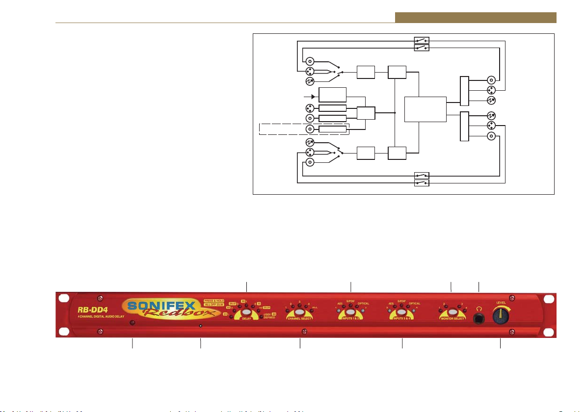
A powerful feature of the RB-DD4 is that by using the
Sonifex SCi serial software, the unit can be programmed for
different delay durations, levels and switching functions so
that you can program the unit for your specific application.
A rear panel DIPswitch configures the unit to be controlled
serially. Contact Sonifex for further information if you have
a particular requirement that isn’t catered for by the RBDD4 as standard.
The RB-DD4 has been designed to have a passive signal
path through the main input, so if power to the unit fails,
signal inputs 1 & 2 are routed to outputs 1 & 2 and signal
inputs 3 & 4 are routed to outputs 3 & 4. This is essential
for applications such as installation at transmitter sites,
where a power failure to the unit should not prevent the
audio input signal from being output to the transmitter.
Please note that this is not true for the TOSLink outputs
which are muted.
Front Panel Controls and Indicators
The LED in the front panel is normally red to indicate power
to the unit.
DELAY
Select & Indicators
AES
AES
Digital Source
Select
Master
Clock
Generation
AES RX
WC RX
VID RX
Digital Input 1
S/PDIF
Optical
Freq Select
AES Sync
Word Clock
Video Optional
Optical
S/PDIF
Digital Input 2
Fig 11-2: RB-DD4 Block Diagram
INPUTS
1 & 2
RX SRC
Clock
Select
RX SRC
Synchronisers & Delays - RB-DD4 11
Power
Failure
Relay
DSP
Power
Failure
Relay
TX
TX
MONITOR
SELECT
Headphone
Socket
Digital Output 1
S/PDIF
AES
Optical
Optical
AES
S/PDIF
Digital Output 2
Power
LED
Fig 11-3: Front Panel Controls and Indicators
Reset
Button
CHANNEL
SELECT
INPUTS
3 & 4
Monitor
Gain Pot
81

11 Synchronisers & Delays - RB-DD4
Fig 11-4: DELAY Button
Fig 11-5: CHANNEL SELECT
Button
82
DELAY Unit & Quantity Select and
Indicators
This button allows you to select the
length of a delay unit and the multiple,
which when multiplied together give the
total delay length.
To set the Delay Unit, press and hold the
DELAY button. A single given LED is lit to
indicate which unit has been selected.
Pressing the button moves the selection
in a clockwise direction.
To set the multiple/quantity of units to
delay, press and hold the DELAY button
again. The LEDS around the button
indicate the chosen delay multiple and
the total multiple is found by summing
the indicated numbers. Pressing the
button increments the multiple by one.
(See page 83 for more info on Delay
Button Modes).
Channel Select
This button selects and indicates the
currently selected input channel.
There is an option for each individual
channel and an option for all channels.
As each different channel is selected,
the currently selected delay multiple
for that channel is displayed on the
DELAY button LEDs. Any change of the
multiple or delay unit length is applied
to the currently selected channel, or
Fig 11-6: INPUTS 1 & 2
Button
Fig 11-7: MONITOR SELECT
Button
all of them if the ALL option is selected. Pressing
the button moves the selection in a clockwise
direction.
INPUT 1 & 2 Source Select, Indicators & Input
Presence LEDs
This button allows you to select which input
source you would like to use for the selected
channel. The three LEDs above the button
illustrate which source is selected. The button
itself is illuminated when the input is locked.
The bicolour LEDs, marked ‘1’ and ‘2’ , show input
presence and give an indication of the input level
using the AES digital standard with the following
colours:
-INF < -52dBFS = OFF
-52dBFS < -3dBFS = GREEN
-3dBFS <0dBFS = ORANGE
INPUT 3 & 4 Source Select, Indicators & Input
Presence LEDs
The operation of this button is identical to above.
MONITOR SELECT button
Press the MONITOR SELECT button to choose
an output to monitor in the headphones. For
monitor selection the button illuminates read and
the LEDS around the button display in red which
channel has been selected.
The button also displays external signal status. If
the selected synchronisation source is unlocked,
the button flashes green
and red.
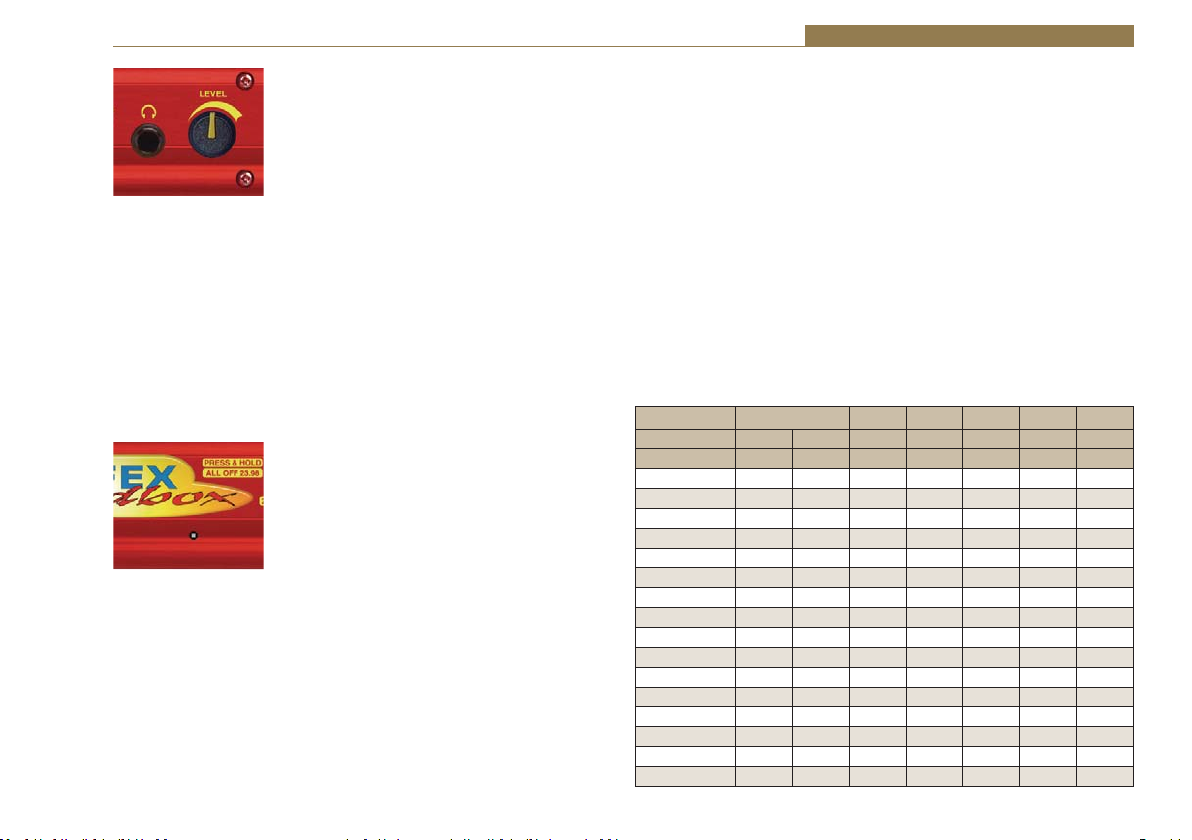
Synchronisers & Delays - RB-DD4 11
Fig 11-8: Headphone
Output & Level Controls
Fig 11-9: Reset Button
Headphone Output
The front panel headphone output is a ¼”
(6.35mm) stereo jack socket capable of delivering
ŽǀĞƌϴϬŵtŝŶƚŽϯϮɏͲϲϬϬɏƉƌŽĨĞƐƐŝŽŶĂů
headphones at full volume. Higher impedance
headphones may be used at reduced levels.
Lower impedance headphones should not be
used.
If the output sounds bad or disturbed at any time,
use the monitor attenuation DIPSwitch 10 to
reduce the headphone output to an acceptable
level - this will depend on the impedance of the
headphones that you are using.
LEVEL Control
The front panel LEVEL control is a potentiometer
that adjusts the level of the monitor output and
provides a gain range of -70dB
to +12dB.
Reset Button
In the unlikely event that the RB-DD4 unit fails to
respond, press the reset button to reboot the unit
(see Fig 1-9 for location).
Delay Button Modes
The Delay button operates in two different
modes:
Delay Unit Select Mode
To select the delay unit press and hold the delay
button for two seconds and then release. The
button turns green. Momentary pressing of the
button moves the Delay Unit selection in a clockwise direction. There are
eight different options for the delay unit with each number corresponding
to a frame per second value with the delay unit length being the reciprocal
of this value. The available choices (in frames per second) are:
23.98, 24, 25, 29.97, 30, 50, 59.94 & 60
Once the delay unit length has been chosen, press and hold the button for
two seconds to return to Delay Multiple mode.
Delay Multiple Mode
This is the default mode for this button and is used to select the quantity,
or multiple, of units to delay by. Press this button to increment the multiple
value from 1 unit to 19. The quantity is displayed as the sum of the LEDS
around the button. The following explains how the LEDs display the
number:
Led Number
Multiple 1234510U D
Minimum Off Off Off Off Off Off Off
1 On Off Off Off Off Off Off
2 Off On Off Off Off Off Off
3 Off Off On Off Off Off Off
4 Off Off Off On Off Off Off
5 Off Off Off Off On Off Off
6 On Off Off Off On Off Off
7 Off On Off Off On Off Off
8 Off Off On Off On Off Off
9 Off Off Off On On Off Off
10 Off Off Off Off Off On Off
11 On Off Off Off Off On Off
12 Off On Off Off Off On Off
13 Off Off On Off Off On Off
14 Off Off Off On Off On Off
15 Off Off Off Off On On Off
16 On Off Off Off On On Off
83

11 Synchronisers & Delays - RB-DD4
17 Off On Off Off On On Off
18 Off Off On Off On On Off
19 Off Off Off On On On Off
User Defined Off Off Off Off Off Off On
When all the LEDs are OFF, the channel uses the minimum delay which is
dependant on the input sample and output sample rates.
Input Samplerate (Hz)
32k 44.1k 48k 88.2k 96k 176.4k 192k
4.594
3.680
3.484
2.472
2.374
1.869
32k
msec
msec
msec
msec
msec
4.247
3.333
3.137
2.125
44.1k
msec
msec
msec
4.172
3.259
48k
88.2k
96k
176.4k
192k
msec
3.788
msec
3.751
msec
3.559
msec
3.540
msec
Output
Samplerate
(Hz)
Fig 11-10: Minimum delay values (at 0 frames) due to inherent delay at different input
to output sample rates within the unit, measured in ms
AES/EBU
Outputs
msec
2.875
msec
2.837
msec
2.645
msec
2.626
msec
S/PDIF
Outputs
3.063
msec
2.678
msec
2.641
msec
2.449
msec
2.430
msec
msec
2.051
msec
1.667
msec
1.629
msec
1.437
msec
1.419
msec
AES/EBU
Inputs
2.027
msec
1.953
msec
1.569
msec
1.531
msec
1.339
msec
1.320
msec
msec
1.522
msec
1.447
msec
1.063
msec
1.025
msec
0.833
msec
0.815
msec
S/PDIF
Inputs
1.819
msec
1.473
msec
1.398
msec
1.014
msec
0.976
msec
0.784
msec
0.766
msec
Rear Panel Controls & Connectors
Rear Panel DIPSwitches
The SETTINGS DIPSwitch block on the
rear panel is used to configure the RMDD4:
Fig 11-11: RB-DD4 Rear Panel DIPSwitch Block
Master Mode Sample Rate Selection (DIPSwitches 1-3)
These DIPSwitches allow you select which sample rate the output is set to
when the unit is synchronised to the Master Mode:
Sample Rate (kHz) DIPSwitch 1 DIPSwitch 2 DIPSwitch 3
32 OFF OFF OFF
44.1 ON OFF OFF
48 OFF ON OFF
88.2 ON ON OFF
96 OFF OFF ON
176.4 ON OFF ON
AES/EBU
Sync Input
192 OFF ON ON
RS232
Fig 11-12: RB-DD4 Rear Panel
84
Optical
Outputs
Optical
Inputs
Word Clock
Input
DIPSwitch
Settings
Serial
Remote

Synchronisers & Delays - RB-DD4 11
Synchronisation Source Selection (DIPSwitches 4-6)
These DIPSwitches allow you select which input sync source is used to
synchronise the unit:
Synchronisation Source DIPSwitch 4 DIPSwitch 5 DIPSwitch 6
Input 1 & 2 OFF OFF OFF
Input 3 & 4 ON OFF OFF
AES/EBU Sync Input OFF ON OFF
Word Clock Input ON ON OFF
Video Sub Board OFF OFF ON
Synchronisation Mode Selection (DIPSwitches 7-8)
These DIPSwitches allow you select the active sync mode:
Synchronisation Mode DIPSwitch 7 DIPSwitch 8
Master Mode OFF OFF
Auto Sync Mode ON OFF
Auto Lock Mode OFF ON
Slave Mode ON ON
Stereo/Mono Operation of the Headphone Monitor (DIPSwitch 9)This
defines whether the monitor operates as a stereo pair or as mono channels
1 & 2.
Mode DIPSwitch 9 Description
Also when ON, the headphone monitor outputs
Stereo ON
Mono OFF
a stereo signal made up of either Input 1 & 2 or
Input 3 & 4.
In Mono Mode the selected signal is sent to left
and right earpieces of the headphone output.
Monitor Attenuation (DIPSwitch 10)
This defines whether the monitor signal is attenuated by 12dB. This is
useful if you’re using low impedance headphones which are too loud in
everyday use.
Mode DIPSwitch 10 Description
Attenuated ON
Unattenuated OFF
Serial Mode (DIPSwitch 11)
This defines whether the unit is in serial mode. In serial mode the unit is
controlled by the serial port, not by its DIPSwitch settings. For example for
use with the Sonifex SCi software.
Mode DIPSwitch 11 Description
Serial Control ON When ON, the unit is in serial mode.
DIPSwitch Control OFF
Boot Mode (DIPSwitch 12)
With this DIPSwitch ON, the unit powers up into ‘Boot Mode’. In this mode,
the firmware in the unit can be upgraded using the SCi software. Note that
this would be useful if a firmware update to the unit was interrupted, or
corrupted which left the unit in an inoperable condition.
Mode DIPSwitch 12 Description
Boot Mode ON
Normal Operation OFF
When ON, the monitor signal is
attenuated.
When OFF, the monitor signal is
unaffected.
When OFF, the unit is in normal
operation.
When ON, the unit is in Boot
Mode.
When OFF, the unit is operates
normally.
85

11 Synchronisers & Delays - RB-DD4
RB-DD4 Inputs
AES/EBU Inputs
dŚĞĚŝŐŝƚĂůŝŶƉƵƚy>ZϯƉŝŶƐŽĐŬĞƚŚĂƐĂŶŝŵƉĞĚĂŶĐĞŽĨϭϭϬɏ/ƚŚĂƐƚŚĞ
following connections:
Pin 1: Screen
Pin 2: Phase
Pin 3: Non-phase
The signals on this connector should meet the IEC 60968 specification
S/PDIF Inputs
dŚĞ^W/&ĚŝŐŝƚĂůƉŚŽŶŽŝŶƉƵƚŚĂǀĞĂŶŝŵƉĞĚĂŶĐĞŽĨϳϱɏ
Optical Inputs
The digital audio optical input meets the TOSLink specification used by most
professional & consumer equipment.
AES/EBU Sync Input
dŚĞĚŝŐŝƚĂůŝŶƉƵƚy>ZϯƉŝŶƐŽĐŬĞƚŚĂƐĂŶŝŵƉĞĚĂŶĐĞŽĨϭϭϬɏ/ƚŚĂƐƚŚĞ
following connections:
Pin 1: Screen
Pin 2: Phase
Pin 3: Non-phase
The signals on this connector should meet the IEC 60968 specification
Word Clock Input
dŚĞǁŽƌĚĐůŽĐŬdd>EŝŶƉƵƚŚĂƐĂŶŝŵƉĞĚĂŶĐĞŽĨϳϱɏ
Video Sync Input
dŚĞŽƉƚŝŽŶĂůǀŝĚĞŽƐLJŶĐŝŶƉƵƚŝƐƉƌĞƐĞŶƚĞĚĂƐĂϳϱɏEĐŽŶŶĞĐƚŽƌ^ĞĞ
page viii for more information on the video sync boards available.
Serial RS232 Connector
The 9-way ‘D’ type socket connector carries a standard RS232 interface and
allows direct connection to a serial port on a PC via a pin-to-pin cable. The
pin assignments are as follows:
Pin 2: Transmit data
Pin 3: Receive data
Pin 5: Ground
All other pins are unused.
Remotes Connector
The remotes connector is a 15-way ‘D’ type socket that is currently reserved
for future development. Displayed below are the pin connections and a
description of what is available:
Pin 1 – Relay 1 Normally Open
Pin 2 – Relay 1 Normally Closed
Pin 3 – Relay 2 Normally Open
Pin 4 – Relay 2 Normally Closed
Pin 5 – Make to Digital Ground Input
Pin 6 – Internal Open Collector to Digital Ground Output
Pin 7 – Make to Digital Ground Input
Pin 8 – Digital Ground
Pin 9 – Relay 1 Common
Pin 10 – Make to Digital Ground Input
Pin 11 – Relay 2 Common
Pin 12 – 5 V Supply Maximum 200 mA
Pin 13 – Internal Open Collector to Digital Ground Output
Pin 14 – Make to Digital Ground Input
Pin 15 – Internal Open Collector to Digital Ground Output
86

Synchronisers & Delays - RB-DD4 11
RB-DD4 Outputs
AES/EBU Outputs
dŚĞĚŝŐŝƚĂůŽƵƚƉƵƚy>ZϯƉŝŶƐŽĐŬĞƚŚĂƐĂŶŝŵƉĞĚĂŶĐĞŽĨϭϭϬɏ/ƚŚĂƐƚŚĞ
following connections:
Pin 1: Screen.
Pin 2: Phase.
Pin 3: Non-phase.
The signals on this connector will comply with the IEC 60968 specification.
S/PDIF Outputs
dŚĞĚŝŐŝƚĂůŽƵƚƉƵƚ^W/&ƉŚŽŶŽŽƵƚƉƵƚŚĂƐĂŶŝŵƉĞĚĂŶĐĞŽĨϳϱɏ
Optical Outputs
The digital audio optical output meets the TOSLink specification used by
most professional & consumer equipment.
The outputs have an unweighted dynamic range of at least 138dB and a
THD+N noise of or better than –137dB. The data at the outputs is presented
as 24 bit wide.
Serial Port Control
The Serial Port allows the RB-DD4 to be controlled and updated from a PC
via a pin-to-pin serial cable, using the Sonifex Serial Control Interface (SCI)
software. This software is available as a free download from the Sonifex
website at www.sonifex.co.uk/sci.
Default Settings for the Serial Port
Baud Rate: 19200
Data Bits: 8
Stop Bits: 1
Parity: Even
Handshaking: XON/XOFF
Fig 11-13: Serial Port Default Settings
Serial Interface Commands and Responses
Most of the commands follow the same structure: a 3 letter command
followed by a colon, followed by a parameter (if any) and terminated by
Carriage Return with optional Line Feed. A Line Feed character may be sent
but it will be ignored by the RB-DD4. Commands are not case sensitive.
Responses are CR & LF terminated.
After the RB-DD4 has been powered-up, an initialisation string is sent
“Initialising DD4”.
Following are the commands and the expected responses:
87

11 Synchronisers & Delays - RB-DD4
Command Description Response
Bnn: Baudrate Change -ACK:
nn is the new baudrate value where:
nn = 11 = 115200kbps
nn = 57 = 57600kbps
nn = 38 = 38400kbps
nn = 19 = 19200kbps
nn = 96 = 9600kbps
CHN:nn Channel Select -ACK:
Where nn represents the channel which is selected
where:
00 = Input 1
01 = Input 2
02 = Input 3
03 = Input 4
04 = All Inputs
DLY: Delay Setup a_b_cc_dddddd -ACK:
a: Channel to apply delay to where
0 = Input 1
1 = Input 2
2 = Input 3
3 = Input4
4 = All Inputs
b: Chosen delay Unit where
0 = Samples
1 = Milliseconds
2 = Fields
3 = Frames
4 = Lines
cc: Choose video standard where
00 = 625/29.97i
01 = 525/25i
02 = 720/60p
03 = 720/59.94p
04 = 720/50p
05 = 720/30p
06 = 720/29.97p
07 = 720/25p
08 = 720/24p
88
Command Description Response
09 = 720/23.98p
0A = 1035/60i
0B = 1035/59.94i
0C = 1080/60i
0D = 1080/59.94i
0E = 1080/50i
0F = 1080/30p
10 = 1080/29.97p
11 = 1080/25p
12 = 1080/24p
13 = 1080/23.98p
14 = 1080/30pSF
15 = 1080/29.97pSF
16 = 1080/25pSF
17 = 1080/24pSF
18 = 1080/23.98pSF
19 = 1080/60p
1A = 1080/59.94p
1B = 1080/50p
dddddd: Number of samples in hex
DWN: Download firmware -ACK:
Initiates a firmware upgrade
FPS: Front panel and unit status
-FPS:aa_bb_cc_dd_ee_ff_gg_hh_ii_jj_kkkkkk_llllll_mmmmmm_nnnnnn_
oooooo
aa: Input 1 & 2 source selection
bb: Input 3 & 4 source selection
where 00 = AES, 01 = SPDIF,02 = TOSLINK
cc: Sync mode selection
where 00 = Master, 01 = Auto, 02 = Auto lock, 03 = Slave
mode
dd: Serial Flag indication
where 00: Serial Mode Off, 01 = Serial mode On
ee: Frequency
where 00 = 32k,01 = 44.1k,02 = 48k,03 = 88.2k,04 =
96k,05 =176.4k,06 = 192k
ff: Monitor Channel
where 00 = OUTPUT1,01 = OUTPUT2, 02 = OUTPUT3,
 Loading...