


Sonifex HY-02
Automatic Telephone Hybrid
User Handbook

This handbook is for use with the following products :
HY-02 Automatic analogue TBU, free standing with PSU
HY-02D Twin automatic analogue TBU, free standing with PSU
HY-02S Automatic analogue TBU, rack mounted with PSU
HY-02T Twin automatic analogue TBU, rack mounted with PSU
RD-02 Ringing detector
RD-02R HY 02 with RD 02, rack mounted with PSU
Sonifex Ltd, 2002
All Rights Reserved
Revision 2.00, June 2002
Sonifex Ltd, 61, Station Road, Irthlingborough,
Northants, NN9 5QE, England.
Tel: +44 (0)1933 650 700
Fax: +44 (0)1933 650 726
Email: sales@sonifex.co.uk
Website: http://www.sonifex.co.uk
Information in this document is subject to change without notice and does not represent a commitment on the part of the
vendor. Sonifex Ltd shall not be liable for any loss or damage whatsoever arising from the use of information or any error
contained in this manual.
No part of this manual may be reproduced or transmitted in any form or by any means, electronic or mechanical,
including photocopying, recording, information storage and retrieval systems, for any purpose other than the purchaser’s
personal use, without the express written permission of Sonifex Ltd. Unless otherwise noted, all names of companies,
products and persons contained herein are part of a completely fictitious adaptation and are designed solely to document
the use of Sonifex product.

Contents
Sonifex HY-02 User Handbook
Contents
Warranty And Safety Information............................................................................... i
Warranty and Liability ........................................................................................................................ i
Unpacking the HY-02.......................................................................................................................... ii
Returning the Warranty Card............................................................................................................... ii
Safety of Mains Operated Equipment .................................................................................................... ii
Voltage Setting Checks....................................................................................................................... ii
Fuse Rating ....................................................................................................................................... ii
Power Cable and Connection ............................................................................................................... ii
Removing the Covers ......................................................................................................................... iii
Faults Sheet ...................................................................................................................................... iv
Introduction ............................................................................................................... 1
What is a Telephone Hybrid ?................................................................................................................................1
Is a Ringing Detector Needed ? .............................................................................................................................1
Which Format is Most Suitable ?............................................................................................................................1
Installing the HY-02 TBU..................................................................................................................... 3
Installing the RD-02R TBU .................................................................................................................. 5
Using the HY-02 ................................................................................................................................ 6
Receiving a Call ..................................................................................................................................................6
Making a Call......................................................................................................................................................6
Front Panel Controls and Displays ........................................................................................................ 6
LED Indicators ....................................................................................................................................................6
Line Connect Switch ............................................................................................................................................6
FAQ (Frequently Asked Questions) ....................................................................................................... 7
Configuration & Controls ............................................................................................ 9
Mains Power Unit Circuit Description .................................................................................................... 9
HY-02 Circuit Description .................................................................................................................... 9
Input Circuits and Limiter .....................................................................................................................................10
Microphone Input Circuits.....................................................................................................................................10
Telephone Line, Barrier and Transformer ................................................................................................................10
Output Circuits ...................................................................................................................................................10
Line Balancing Electronics.....................................................................................................................................10
Analogue Line Circuits..........................................................................................................................................11
Divert Switch Logic..............................................................................................................................................11
Protection Circuitry..............................................................................................................................................11
HY-02 Alignment Procedure ................................................................................................................ 12
HY-02 Internal Controls & Adjustments ................................................................................................ 13
Auto Disconnect – K-Break ...................................................................................................................................13
Auto Dial Tone Detect ..........................................................................................................................................13
Adjusting Output Level.........................................................................................................................................13
Adjusting the Microphone Gain Level......................................................................................................................13
Changing Remote Status From Momentary to Permanent .........................................................................................13
Removing Remote Lamp Dim Function ...................................................................................................................13
Using a LED for the Remote Lamp .........................................................................................................................13
Switching the Noise Gate On/Off ...........................................................................................................................13
Adjusting the Noise Gate Threshold .......................................................................................................................13
Technical Specification ............................................................................................... 15
HY-02 Connection Details.................................................................................................................... 15
Line Input ..........................................................................................................................................................15
Mic Input ...........................................................................................................................................................15
Line Output ........................................................................................................................................................15
Handset .............................................................................................................................................................15
NTTP Port...........................................................................................................................................................15
Remote..............................................................................................................................................................15
Power 1 & Power 2 ..............................................................................................................................................16
Mains Power .......................................................................................................................................................16
Protective Earth Terminal .....................................................................................................................................16
RD-02R Connection Details ................................................................................................................. 16
Divert Control .....................................................................................................................................................16
Ring Lamp..........................................................................................................................................................16
Technical Specification ........................................................................................................................ 17
Physical Specification ......................................................................................................................... 17
Accessories ....................................................................................................................................... 17
Recommended Spare Parts ................................................................................................................. 17
Approvals Information ........................................................................................................................ 18
Manufacturer ......................................................................................................................................................18
Equipment Type..................................................................................................................................................18
BABT Approval Numbers ......................................................................................................................................18
Functions ...........................................................................................................................................................18
Specified Systems ...............................................................................................................................................18
Ringer Equivalence Number ..................................................................................................................................18
Accessory Ports...................................................................................................................................................18

Contents
Sonifex HY-02 User Handbook
Conditions .........................................................................................................................................................18
Series Connection ............................................................................................................................................... 18
Facilities ............................................................................................................................................................18
Statutory Mark ...................................................................................................................................................18

Warranty and Safety Information
Sonifex HY-02 User Handbook i
Warranty And Safety Information
Warranty and Liability
Important: the purchaser is advised to read this clause
(a) The Company agrees to repair or (at its discretion) replace Goods which are found to be defective (fair wear and tear
excepted) and which are returned to the Company within 12 months of the date of despatch provided that each of the
following are satisfied:
(i) notification of any defect is given to the Company immediately upon its becoming apparent to the Purchaser;
(ii) the Goods have only been operated under normal operating conditions and have only been subject to normal use
(and in particular the Goods must have been correctly connected and must not have been subject to high voltage or
to ionising radiation and must not have been used contrary to the Company's technical recommendations);
(iii) the Goods are returned to the Company's premises at the Purchaser's expense;
(iv) any Goods or parts of Goods replaced shall become the property of the Company;
(v) no work whatsoever (other than normal and proper maintenance) has been carried out to the Goods or any part
of the Goods without the Company's prior written consent;
(vi) the defect has not arisen from a design made, furnished or specified by the Purchaser;
(vii) the Goods have been assembled or incorporated into other goods only in accordance with any instructions issued
by the Company;
(viii) the defect has not arisen from a design modified by the Purchaser;
(ix) the defect has not arisen from an item manufactured by a person other than the Company.
In respect of any item manufactured by a person other than the Company, the Purchaser shall only be entitled to the
benefit of any warranty or guarantee provided by such manufacturer to the Company.
(b) In respect of computer software supplied by the Company the Company does not warrant that the use of the
software will be uninterrupted or error free.
(c) The Company accepts liability:
(i) for death or personal injury to the extent that it results from the negligence of the Company, its employees (whilst
in the course of their employment) or its agents (in the course of the agency);
(ii) for any breach by the Company of any statutory undertaking as to title, quiet possession and freedom from
encumbrance.
(d) Subject to conditions (a) and (c) from the time of despatch of the Goods from the Company's premises the Purchaser
shall be responsible for any defect in the Goods or loss, damage, nuisance or interference whatsoever consequential
economic or otherwise or wastage of material resulting from or caused by or to the Goods. In particular the Company
shall not be liable for any loss of profits or other economic losses. The Company accordingly excludes all liability for the
same.
(e) At the request and expense of the Purchaser the Company will test the Goods to ascertain performance levels and
provide a report of the results of that test. The report will be accurate at the time of the test, to the best of the belief
and knowledge of the Company, and the Company accepts no liability in respect of its accuracy beyond that set out in
Condition (a).
(f) Subject to Condition (e) no representation, condition, warranty or other term, express or implied (by statute or
otherwise) is given by the Company that the Goods are of any particular quality or standard or will enable the Purchaser
to attain any particular performance or result, or will be suitable for any particular purpose or use under specific
conditions or will provide any particular capacity, notwithstanding that the requirement for such performance, result or
capacity or that such particular purpose or conditions may have been known (or ought to have been known) to the
Company, its employees or agents.
(g) (i) To the extent that the Company is held legally liable to the Purchaser for any single breach of contract, tort,
representation or other act or default, the Company's liability for the same shall not exceed the Price of the Goods.
(ii) The restriction of liability in Condition (g)(i) shall not apply to any liability accepted by the Seller in Condition (c).
(h) Where the Goods are sold under a consumer transaction (as defined by the Consumer Transactions (Restrictions on
Statements) Order 1976) the statutory rights of the Purchaser are not affected by these Conditions of Sale.

Warranty and Safety Information
ii Sonifex HY-02 User Handbook
Unpacking the HY-02
Each HY-02 is shipped in protective packaging and should be inspected for damage before use. Where an item is found to
have transit damage, notify your supplier immediately with all the relevant details of the shipment. Packing materials
should be kept for inspection and also for if the product needs to be returned.
Returning the Warranty Card
In order to register the date of purchase so that we can keep you informed of any design improvements or modifications,
it is important to complete the warranty registration document that is enclosed and return it to Sonifex Ltd in the UK.
For your own records you should write down the serial number (which can be found on the rear of the HY-02).
Serial Number ………………………………..
Safety of Mains Operated Equipment
This equipment has been designed to meet the safety regulations currently advised in the country of purchase and it
conforms to the safety regulations specified by use of the CE Mark.
Warning : There are no user serviceably parts inside the machine. If you should ever need to look inside the unit,
always disconnect the mains supply before removing the equipment covers.
Warning: This apparatus is intended for use when powered by the HY-02-B power supply unit. Other usage will
invalidate any approval given to this apparatus if, as a result, it ceases to comply with the edition of BS6301 to which it
was approved.
Warning: The equipment B.T. plug should only be connected with apparatus complying with BS6301 and the connection
to the network must not be hard wired. Interconnection directly or indirectly with equipment ports marked in accordance
with BS6301 to unmarked ports may produce hazardous conditions on the network and advice should be obtained from a
competent engineer before such a connection is made.
Warning: This apparatus must be earthed by means of the earth connector on the rear panel, and the B.T. plug should
be disconnected from the telecommunications network before disconnecting the earth. Disconnection of this earth
connection may render the equipment unsafe, with a consequential possible electrical shock hazard from exposed metallic
parts.
Warning: The barriered ports ‘NTTP’ and ‘Handset’ must not be connected directly or indirectly to the unbarriered ports,
‘Line Input’, ‘Line Output’, ‘Mic Input’ or ‘Remotes’.
Voltage Setting Checks
The rear panel of the equipment carries the Serial Number of the machine. The operating voltage of the HY-02 is hardwired to be either 115V or 230V. Ensure that the machine operating voltage is correct for your mains power supply. The
safety specification of your HY-02 complies with local requirements and must be earthed through the mains connector.
The available voltage settings are : -
Country code A 115 V operation
Country code E 230 V operation
Fuse Rating
The HY-02 is supplied with a single fuse in the live conducting path of the power infeed at the power supply. For reasons
of safety it is important that the correct rating and type of fuse is used. Incorrectly rated fuses could present a possible
fire hazard, under equipment fault conditions. The fuse ratings for HY-02 are :-
Country code A 115 V operation - 200mA 5 x 20mm SB
Country code E 230 V operation - 100mA 5 x 20mm SB
The active fuse is fitted at the power supply on the outside of the unit.
Power Cable and Connection
An IEC power connector is supplied with the HY-02 which has a moulded plug attached – this is a legal requirement. If no
moulded plug has been supplied with your HY-02, please contact your supplier, because an IEC connector is always
supplied from the Sonifex factory.

Warranty and Safety Information
Sonifex HY-02 User Handbook iii
If for any reason, you need to use the HY-02 with a different power cable, you should use the following wiring guidelines
Wire Colour Connection
Green, or green and yellow Earth (E)
Blue, or Black Neutral (N)
Brown, or Red Live (L)
Connect the equipment in accordance with the connection details and before applying power to the unit, check that the
machine has the correct operating voltage for your mains power supply.
Important Note : The terminal marked
on the rear panel must be earthed.
Removing the Covers
Warning : The power must be switched off at the supply or the power lead must be disconnected before attempting to
remove the panels or cover. Removal of the panels and cover can expose dangerous voltages.
Warning : The B.T. plug should be disconnected from the telecommunications network exchange line before removing
the equipment covers.

Warranty and Safety Information
iv Sonifex HY-02 User Handbook
Faults Sheet
Although this Sonifex product is manufacture to the highest standards, it is possible that minor faults may appear in the
equipment over its normal lifetime. If you find any problems with the HY-02, please contact your Sonifex distributor, or
contact Sonifex directly at the following address, or fax with a copy of this completed sheet :
To : Sonifex Ltd, From: Name .......................................................
61, Station Road, Position .......................................................
Irthlingborough, Company .......................................................
Northants. Address .......................................................
NN9 5QE, UK .......................................................
.......................................................
Tel : +44 (0)1933 650 700 Tel .......................................................
Fax : +44 (0)1933 650 726 Fax .......................................................
For the Serial No. of your machine, see the back panel of the HY-02 unit.
HY-02 Serial No. HY-02 Power Supply Serial No.
Please describe the error in as much detail as possible ( for example what you were doing when the problem occurred,
what actually happened, etc).
Description of HY-02 Error
Also, if you have any suggestions for additions or upgrades to the HY-02 unit , we would like to hear what they are :
Additions that I Would Like to See

Introduction
Sonifex HY-02 User Handbook 1
Introduction
The HY-02 is a high quality analogue telephone hybrid which is suitable for most general telephony applications and is
often used in radio and TV stations, bingo halls and dealing floors. The HY-02 can be used for any application where a
clean telephone signal is required and the line is not subject to delay.
Sonifex have been manufacturing the analogue HY-02 telephone hybrid for many years and have sold over 3,000 units
worldwide.The HY-02 has set the standard as an excellent value, high quality telephone hybrid. Some of the features for
the HY-02 range include :
• Fully automatic - they automatically adapt to varying line conditions and have automatic signal limiting.
• Local and remote line hold switching - calls can be remotely switched through a mixing console.
• Balanced inputs and outputs - 0dBu transformer balanced 10k bridging clean feed line input and 0dBu low impedance
transformer balanced output.
• 28 dB typical line balance rejection.
• BABT approval complaint with European PTT specifications.
• Balanced microphone level input with 74dB adjustable gain.
• Line limiter, bandpass filter and output noise gate with preset threshold providing low distortion crystal clear audio.
• Fitted with K-break as standard with an option for dial-tone disconnect (HY-DTD add-on board).
What is a Telephone Hybrid ?
Telephone hybrids (or telephone balance units) provide the interface between professional audio equipment and the
public telephone network. They provide protection for your equipment and the public telephone lines, allowing for varying
line signals and line conditions. Automatically canceling out the unwanted signal they also facilitate two-way
communication down a single telephone line, converting the two-wire telephone signal to a four-wire send and return
signal to be linked to a studio mixer, for example.
Each hybrid has a telephone line connection and separate terminals for audio input and output from a broadcast mixer, or
other professional audio source.
A large proportion of Sonifex hybrids are used in radio and television broadcasting applications for allowing external
callers to be connected to the studio mixing console. Most of the other units are supplied to communication operations for
allowing extremely effective conversion between four-wire audio circuits and standard telephone lines. Built to a very
high specification, the HY-02 is simple to install and automatically adapts to line conditions and programme content.
Is a Ringing Detector Needed ?
Ringing detectors can be used when you need to answer a call automatically, for instance, if a journalist files a report to a
tape recorder over a telephone line, the call can be picked up after a set number of rings by the ringing detector.
Which Format is Most Suitable ?
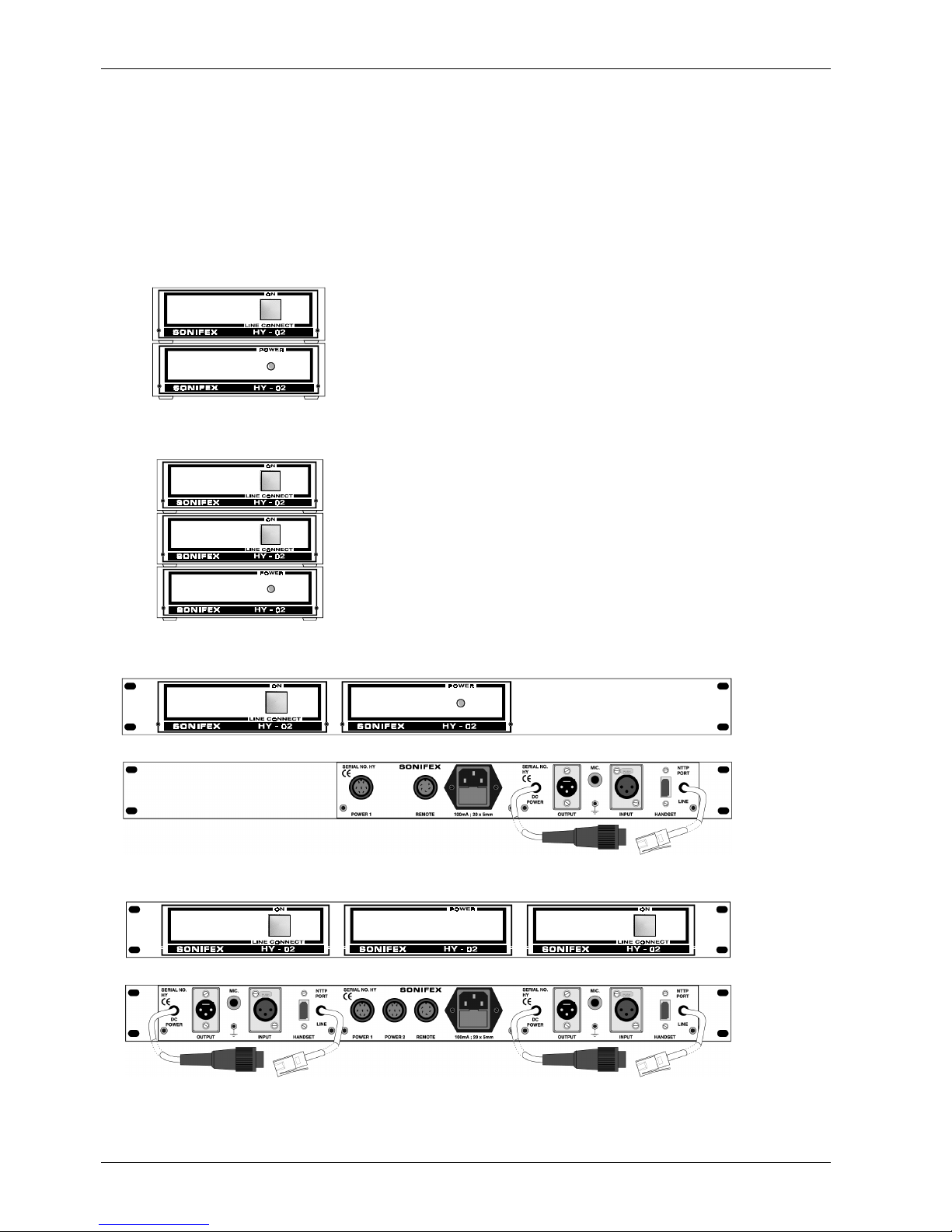
The HY-02 analogue telephone hybrids are available as free standing, or 1U 19” rack-mount units, supplied in either
single or twin configurations. Each has a separate approved power supply. The hybrid can also be supplied as a single
eurocard. Ringing detectors are available as a seperate free standing unit, as a eurocard, or can be rack-mounted with a
single HY-02 (the RD-02R).
Eurocards are supplied without a power supply, or casing and are therefore significantly cheaper than the other units.
The cards can be slotted into a rack and located by the bracket at the front of the card. They are mainly used in mixing
consoles, or other systems, which have been designed specifically with slots to hold eurocard equipment. Where multiple
Analogue
Free-standing
Rack-mounted Eurocard
Single
Twin
HY-02 HY-02D
Ringing
detector
RD-02
With ringing
detector
Without ringing
detector
Single
Twin
Single
RD-02R
HY-02S
HY-02T
Ringing
detector
HY-02EC
RD-02EC
Introduction
2 Sonifex HY-02 User Handbook
units are required, they can be slotted into a rack and connected to a single power supply unit, saving money on
duplicating power supplies and casing.
The HY-02 consists of two parts:
1. A telephone hybrid section. This can be either a telephone hybrid or a ringing detector.
2. The power supply section. This supplies ±15V d.c. to the electronic hybrid section and is connected to the telephone
hybrid processor by means of short link cables. It has an overvoltage protected output and is separately enclosed. It
is supplied as a single unit for use with one telephone hybrid unit or as a dual unit for the twin hybrids (HY-02D and
HY-02T). Earth bonding from the mains IEC input connector is carried through the connection cable and multiway
socket to the electronic hybrid unit.
HY-02 Automatic TBU, free standing with PSU
HY-02D Twin automatic TBU, free standing with PSU
HY-02S Single automatic TBU, rackmounted with PSU
HY-02T Twin automatic TBU, rack mounted with PSU

Introduction
Sonifex HY-02 User Handbook 3
RD-02 Ringing detector
RD-02R HY-02 with RD-02, rack mounted with PSU
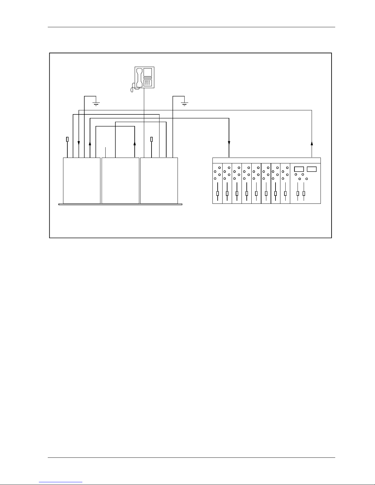
Installing the HY-02 TBU
Connect the power and earth connections as per the information given in the Warranty and Safety Information section of
the handbook. The hybrid unit should be connected with reference to Figure 1-1 below which shows the connections for a
twin hybrid. If you are using a single hybrid, use the connections of the HY-02 Hybrid Unit 1.
Figure 1-1 HY-02 User Connections
The telephone line NTTP port may be directly connected using the BT 6/502 cable mounted connector into a suitable BT
wall jack socket. A simple telephone handset can be used to take and make calls when plugged into the equipment
HANDSET connector BT 605A.
The connector labelled Line Input is balanced bridging and will accept normal signals at 0dBu peaking to +8dBu from a
sound mixer ‘clean feed’. The input circuitry to the HY-02 has a very effective limiter which will prevent high level
overloading problems. However, ideally, the maximum input level should not exceed +12 dBu.
Power 2
Line Output
Earth
Line Input
Handset Port
NTTP Port
Power 1
Line Output
Earth
Line Input
Handset Port
NTTP Port
Power 2
Power 1
Remotes
Mains
HY- 02
Hybrid Unit 1
HY- 02
Hybrid Unit 2
Mixing DeskHY -02
Power Supply
BT Line
Plug
Handset
Earth Earth
Handset
BT Line
Plug
Remote
Divert
Mains
Power
Inputs to
Telephone
Channels
Outputs from
Mixer Clean-Feed

Introduction
4 Sonifex HY-02 User Handbook
The MIC INPUT will accept 200 ohm microphone level signals and is balanced/floating with a maximum gain of 74dB. It is
suitable for a wide range of microphones and the available gain is 74 dB to 40 dB preset by the internal gain control. The
microphone channel drives the telephone line through the line limiter with similar overload conditions.
The LINE OUTPUT connection will deliver a balanced/floating low impedance signal of 0dBm from the telephone line. The
output of the digital hybrid unit is normally 0dBu from a balanced source of 50 ohms or less across the useful bandwidth
of the equipment. The bandwidth is restricted by the line conditions between 250 Hz and 4 kHz. The output stage is
capable of driving into 600 ohm loads at up to +8dBu. Termination of the output is not necessary however and direct
connection can be made into the mixer telephone return channel. The output stage has an internal present gain control
which may be set to give 0 dB signals at the output. In addition an output noise gate operates when the telephone signal
is below the noise gate threshold control. This noise gate reduces the output gain by 34 dB under no signal conditions
eliminating the affects of telephone line cross talk. The noise gate is factory set to –26 dBu to avoid interaction with the
equipment null.
Isolation of better than 28dB is created between the input and output connectors when the hybrid unit is functioning on
an exchange line.
Connect the connector labelled “DC POWER” from the back of the hybrid unit to the power supply. The power supply
creates ± 15V dc to power the electronic hybrid processor from a 230V, 50Hz ac supply. The power unit has an
overvoltage protected output and is fully isolated and totally enclosed. Earth bonding from the IEC power connector is
carried through the connection cable and multiway socket to the electronic hybrid processor unit. The earth terminal at
the rear of the equipment provides protection for the user against dangerous line fault conditions.
A remote divert switch may be connected at the REMOTES socket in order to control the LINE CONNECT switch from, say,
the telco channel of a mixing desk.
A remote divert switch may be connected at the REMOTE DIVERT socket. The connector labelled LINE INPUT will accept
0 dB line signals and is a balanced/floating input.
The earth terminal at the rear of the equipment provides protection for the user against dangerous line fault conditions.
Note : The earth bond at the screw terminal must be connected to a technical earth to ensure the safe
operation of the equipment under all line conditions.
Introduction
Sonifex HY-02 User Handbook 5
Installing the RD-02R TBU
The connection details for the HY-02 with ringing detector are similar to those for the HY-02 single unit :
Connect the lead from the DIVERT CONTROL connector on the rear of the ring detector section to the REMOTES
connector on the rear of the power supply. The NTTP port connection from the RD-02 should be connected to the
HANDSET connector on the rear of the HY-02 unit. Make all the other connections as for a single HY-02.
You should now use the REMOTES connector on the back of the ring detector section to connect a remote divert switch.
The ringing detector will detect incoming ringing tone and automatically switch the HY-02 ‘on-line’ and hold the call by
means of the remote divert connection. The RD-02 is on-line before and during the ringing cadence and is switched offline during call holding.
E
a
r
t
h
D
i
v
e
r
t
C
o
n
t
r
o
l
N
T
T
P
P
o
r
t
R
e
m
o
t
e
I
n
H
a
n
d
s
e
t
P
o
w
e
r
1
L
i
n
e
O
u
t
p
u
t
E
a
r
t
h
L
i
n
e
I
n
p
u
t
H
a
n
d
s
e
t
P
o
r
t
N
T
T
P
P
o
r
t
P
o
w
e
r
1
P
o
w
e
r
2
R
e
m
o
t
e
s
M
a
i
n
s
HY -02
Hybrid Unit
RD- 02
Ringin g D etector
Mixing DeskHY- 02
Power Supply
BT Line
Plug
Remote
Earth Earth
Handset
Mains
Power
Input to
Telephone
Channel
Outputs from
Mixer Clean-Feed

Introduction
6 Sonifex HY-02 User Handbook
Using the HY-02
Receiving a Call
With the equipment connected as in Figure 1-1 calls may be received and detected by the ringer in the telephone
handset. To receive the call lift the handset and establish contact with the caller. The call may be diverted to the
telephone hybrid by pressing either the local LINE CONNECT switch at the front panel or by means of the remote DIVERT
switch (if connected).
The hybrid unit will now behave as a 4 wire to 2 wire convertor with signal inputs at LINE or MIC Input and telephone
signal output at LINE output.
The call may be cleared by repressing the LINE CONNECT switch or by means of the K-break provided in the equipment.
(Automatic line clearance is provided when the caller hangs up when pins T2 and T3 are linked on the HY-02-A circuit
board).
Alternatively, the ringing detector RD-02 may be connected to the series connection ‘HANDSET’ of the HY-02 and the
handset connected to the HANDSET connection of the RD02 ringing detector, as in Figure 1-2. This connection will allow
you to auto-answer incoming calls. It is recommended that the K-break line clearance is used with any ringing detector
connection. When the ringing detector is in use, ringing tone will energise the LINE CONNECT switch through the
interconnection between the two units HY-02 and RD-02 to provide auto answer of incoming calls. The LINE CONNECT
switch lamp is ‘DIM’ in the non’ connected mode and ‘BRIGHT’ in the connected mode.
With both auto-answer and auto-clearance in use, call handling can be completely automatic in operation.
Making a Call
To initiate a call, lift the handset and dial the required telephone number. When the call has been established, press the
LINE CONNECT switch and the call will be handed over to the telephone hybrid unit. To clear the line at the end of the
call, press the LINE CONNECT switch. The LINE CONNECT switch lamp is ‘DIM’ in the non-connected mode and ‘BRIGHT’
in the connected mode.
Please note that any adjustments and settings should be carried out by competent engineering personnel.
Front Panel Controls and Displays
LED Indicators
There is one LED indicator providing general information about the equipment. A status LED, marked “On”, shows that
the equipment is powered and operational.
Line Connect Switch
This is the front panel button used to connect calls to and disconnect calls from the telephone line. It can be remoted by
using a Remote Divert switch and the connection signal can be made permanent or momentary by adjusting switch
setting SW1 (see page 11 for further information).

Introduction
Sonifex HY-02 User Handbook 7
FAQ (Frequently Asked Questions)
The answers to most of the following questions are available elsewhere in the handbook, but have been summarised here
for convenience.
Q : What are the remote connection details for these units ?
A : The HY-02 is equipped with a 5 way IP40 socket (678 series) which is assigned as follows :
Pin 1 : Lamp Hybrid Unit 1
Pin 2 : Divert Switch (Line Connect), Hybrid Unit 1
Pin 3 : Common
Pin 4 : Lamp Hybrid Unit 2
Pin 5 : Divert Switch (Line Connect), Hybrid Unit 2
The mating connector (plug) for this remote is supplied with your HY-02 unit. Check your packaging if you can’t find it
as often, this is thrown out when unpacking. If you need to order one, it is Sonifex part number 45-505.
Q : What type of remote lamp should be used ?
A : The remote lamp type should be 18V at 40mA.
Q : I want the remote lamp to be ON to indicate line diverted, but not dim when the line is not diverted. How do I do this ?
A : Remove R12 from the circuit on the HY02-4 PCB. It should work ok then.
Q : I want to use a LED for the remote lamp. How do I do it ?
A : As above, remove R12 from the circuit on the HY02-4 PCB. It should work ok then.
Q : What are the connections for the telephone wire ?
A : The telephone line is connected via the white and red wires on the connector. So you know which pin is which, the
latch is adjacent to Pin 6.
Pin 1 : Not used
Pin 2 : White wire, BT line A
Pin 3 : Green wire, Earth recall
Pin 4 : Blue wire, Ringer
Pin 5 : Red wire, BT line B
Pin 6 : Not used
Q : The handset connected to the unit doesn't ring. What's wrong ?
A : If the handset connected to the unit does not ring but still works o.k., the ringer shunt wire (blue wire pin 4) has
become open circuit. Or, if it has never worked since installation, the extension wiring will need checking.
Q : What is the power consumption of the HY-02 telephone hybrid ?
A : <6W for HY-02, HY-02S, RD-02R and <12W for HY-02T and HY-02D. The RD-02 draws power from a connected unit.
Q : The telephone hybrids don't automatically disconnect on dial-tone. Why not?
A : This is correct as there is no dial tone disconnection unless the HY-DTD dial tone detect option has been added. If the
HY-DTD option has been added and you still have this problem, then the unit is probably connected to a PABX, or a
non British Telecom network (i.e. not used in the UK) and so, the dial tone detect circuit needs changing. Contact
Sonifex technical support, technical.support@sonifex.co.uk for further information.
Q : The telephone hybrid unit keeps "dropping the line". How can I stop this happening?
A : Firstly, try disabling the k-break function of the hybrids - disconnect the link wire between terminals T2 and T3.
If you still have a problem once the k-break is disconnected, please contact Sonifex technical support,
technical.support@sonifex.co.uk

Introduction
8 Sonifex HY-02 User Handbook
This page is deliberately blank.

Configuration & Controls
Sonifex HY-02 User Handbook 9
Configuration & Controls
The HY-02 telephone hybrid consists of two parts separately enclosed for safety within a 19” rack frame housing. The
two parts are connected by linking cables at the rear of rack frame. Isolation is achieved by means of the barriers
created at the power supply and the hybrid electronics.
Mains Power Unit Circuit Description
The mains power is available in either single or double configuration for use with either one or two electronic hybrid units,
within one rack frame assembly.
The 230V 50Hz, or 115V 60Hz, mains connection is via an IEC fused connector type CEE22. The 230V supply generates
low voltage a.c. through an isolation transformer(s) TR1 (TR2) the outputs of which are smoothed and regulated to ±15V
d.c. by means of the electronic regulators Q1 and Q2 (Q3, Q4). The ± 15V supply, the earth bond and the remote
connections are connected to the electronic hybrid through the power cable at the rear of the power supply.
The ± 15V d.c. output of the power supply is protected against high voltage breakdown by d.c. fuses F1, F2 (F3, F4) and
the voltage sensitive zener diodes D1, D2 and (D7, D8) in the twin configuration.
A single overvoltage fault will cause overvoltage current to flow in D1 and D2 (D7, D8) rupturing fuses F1, F2 (F3, F4)
removing the overvoltage condition.
HY-02 Circuit Description
Figure 2-1 : HY-02 Block Diagram
The electronic digital hybrid unit comprises the following sections:
• Input circuits and limiter.
• Microphone input circuits.
• Telephone line, barrier and transformer.
• Output circuits.
• Line balancing electronics.
• Analogue line circuits.
• Divert switch logic.
• Protection circuitry.
Mic Amp
Mic
Input
Line
Input
Buffer
Band
Shaping
Limiter
Resistive
Balance
Circuits
Sample
& Hold
Sample
& Hold
Dummy
Load
Driver
Dummy
Load
Driver
Phase
Error
Circuits
240V
50Hz
Power
Unit
DC
Power
Band
Shaping
Noise
Gate
Threshold
Output
Amplifier
Return
Gain
Output
Balanced
Analogue
Line
Double
Pole
Relay
Dis-
connection
Barrier
Tel e ph on e
Handset
Line Connect
Switch
HY-02 Block Diagram

Configuration & Controls
10 Sonifex HY-02 User Handbook
Input Circuits and Limiter
The line input connection at the 3 pin XLR connector is coupled directly to the line bridging input transformer TR2. The
input impedance is greater than 10K ohms balanced floating with a high common mode rejection ratio. The input
transformer is coupled via a resistive attenuator R21, R22 and R24 to the limiter amplifier Q3 bcd and Q12. The limiter
output delivers full bandwidth signals to the bandpass filter formed by Q4c, the output of which drives the telephone line
transformer through the feed resistor R41. The dummy line balancing transformer TR4 is also driven from this point
through feed resistor R42. The limiter incorporates a signal mute operated by Q3a during handset operation.
Microphone Input Circuits
The HY02 is supplied with the microphone transformer TR1 disconnected and a ground link in PL5. If the microphone
input is used it will be necessary to remove the link from PL5 and plug the transformer TR1 in. Microphone gain is set by
the MIC GAIN preset control RV1 in the feedback path of the microphone amplifier circuit Q2 which is coupled to the
limiter input stage. The microphone input level control gives a gain range of 30 dB with a maximum available gain of 74
dB and an input impedance of 200 ohms balanced floating.
Telephone Line, Barrier and Transformer
The telephone line port is a two wire connection into the apparatus through a line cord and jack BT 6/502, with a surge
arrester BT 14A from the A and B wires to earth. The line connection is switched by a divert switch and relay between the
hybrid unit and the handset connected through a BT 605A connector.
The line is held, on the equipment side, by an electronic line holding circuit Q20 and Q21 the A leg fed through a 2.2 uF
250V d.c. blocking capacitor to the line transformer ETAL P1200. A pair of zener diodes arranged in a back to back
configuration across the primary of the line transformer, are arranged to act as overvoltage protection. The line is
balanced/floating with a high common mode rejection ratio. The line transformer is designed to meet BS 6305.
Figure 2-2 : Telephone Barrier Circuitry
Output Circuits
The output from the differential amplifier Q6a which acts as a high gain nulling amplifier is fed to the bandpass stage
formed by Q4a and Q4d. The filtered output is coupled to a mute stage and noise gate formed by Q5 abc, Q15a and Q23.
The threshold of the noise gate is set by preset control RV4. The range of the noise gate threshold control is 30 dB about
a minimum threshold level of -40 dB ref. O dB output. The output amplifier formed by Q5d, Q13, Q14 drives the 600
ohm output transformer coupled by C21. The output level may be adjusted by the preset OUTPUT LEVEL control RV3
with a gain range of 12 dB. This control effectively sets the telephone return signal level and gives adjustment for low
level incoming signals. The output impedance is less than 50 ohms balanced floating.
Line Balancing Electronics
The line is balanced and offers rejection of the input signal at the output when an input signal is present above a set
threshold level. This line balance technique is achieved electronically during input signals and stored in a sample and
hold circuit. Balancing is achieved by utilising a dummy telephone line transformer arranged in a bridge configuration.
The analogue line consists of a network of electronically variable resistance and capacitance arranged in a feedback
circuit, automatically adjusting the analogue line components to provide resistive balance and reactive balance.
The telephone line transformer and the analogue line transformer are arranged in a bridge the output of which drives a
differential amplifier Q6a. The ‘unbalance’ signal of this bridge is amplified and processed as below to give d.c. voltages
which drive the resistive and reactive analogue line elements.
Amplified ‘unbalanced’ signals are switched by the gate Q15b, driven by an amplified in-phase component of the input
signal at Q7c. Q7a and Q7b together with Q7d set the threshold level of in-phase gating.
Telephone Line Disconnection Barrier,
Call Holding and Isolation Transformer Circuit.
Telephone
Line
BT 6/502
Surge
Arrestors
BT 14 A
Relay Type
Series 21
BT 605A
Handset
BC546
82k
6.2V
1.2W
Zene r
150R
82k
22uF
35V
51V
Zene r
1N4004
Electronic Line Holdin
g
2.2uF
250V dc
0.068uF
250V dc
680R
6.2V
1.2W
Zene r
Tra nsfo rmer
Typ e E t a l
P1200
Equipment

Configuration & Controls
Sonifex HY-02 User Handbook 11
In-phase components of the error signal are switched by Q15b and dumped into the storage capacitor C37, the polarity
of the signal being determined by the relationship between the error and the gating pulse. The stored d.c. signal is offset
by Q8a and drives the variable resistor formed by Q16 and Q8b. The resistive error balancing system has a short charge
time constant and a long ‘decay’ time constant.
After resistive balancing is achieved by the closed loop system the remaining error is reactive. An amplified reactive
error is switched by Q15c and dumped into the storage capacitor C43. This d.c. error is offset by Q8d and used to drive
the variable reactance formed by Q17 and Q8c.
The closed loop formed by these error amplifiers reduces the resistive and reactive components of bridge imbalance to a
minimum during input signal excursions above the ‘sample threshold’ level. During no signal conditions the line ‘balance’
is stored and held on capacitors C37 and C43.
Analogue Line Circuits
In order to ‘balance’ the bridge formed by the telephone line transformer and the dummy line transformer a dummy or
analogue line is formed having both resistive and reactive components. In the ideal case the ‘bridge’ will autobalance to
give a good null, compensating for the variations in line resistance and reactance.
The analogue line components are formed by R43, R44, Q16, Q8b and Q17, Q8c. The variable resistance formed by R83
and Q8b has an operating range determined by the gain of the stage Q8b and an absolute value determined by the
setting of the preset RV6. Similarly the variable reactance formed by C44 and Q8c has a range determined by C44 and
the gain of the stage Q8c and an absolute value determined by the setting of RV7.
RV6 and RV7 are set to the correct operating values at 1000Hz by utilising a model line in place of the telephone line
connection with SW1B and SW1C in the closed position.
Divert Switch Logic
With the system unenergised the logic allows the telephone line to be connected to the handset through relay RL1.
The logic circuits Q1a and Q1b change the state of the relay contacts diverting the telephone line to the equipment, when
the divert switch is activated. The logic is edge triggered and will accept remote commands and also drive the indicator
lamp at the switch and remote lamp contacts. The divert switch can either be momentary or permanent, (SW1).
The logic holds the relay in the divert condition until either power is removed or the switch is operated again.
A signal from the logic operates input muting when the handset is in use preventing spurious output signals at the
equipment.
Protection Circuitry
There are three basic protection areas :
• The power supply is protected at its output against excessive voltages within the power supply exceeding the barrier
rating. This protection is in the form of zener diode voltage sensors and fuses directly at the power supply low voltage
output.
• Reinforced insulation isolating the telephone line is provided by the line isolation transformer TR3.
• Protection of the apparatus from excessive line voltages is provided by the voltage sensor LP1 at the line input to the
equipment.
Configuration & Controls
12 Sonifex HY-02 User Handbook
HY-02 Alignment Procedure
The HY-02 is aligned and tested at the factory before you receive it, so that this procedure does not need to be carried
out before use. Please note that you should only realign the product if you have sufficient knowledge and test equipment
to do so and it has been advised by a Sonifex member of staff.
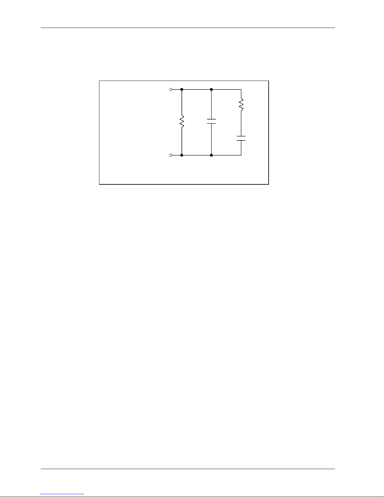
Connect the equipment with a line analogue circuit in place of the telecommunications network (Figure 2-3) and ensure
that the line input is connected to a signal source and the line output is connected to a measuring instrument.
Figure 2-3 : Line Analogue Circuit
The internal DIL switches SW2 – (See Figure 2-4) should be at the ‘ON’ position giving Noise Gate Threshold – ‘OFF’, CAP
SET – ‘ON’ and RES SET – ‘ON’.
Power the equipment and operate the line divert switch connecting the equipment to the line analogue. With 0 dB at
1KHz at the line input measure the voltage across the line analogue, which should read – 9dB. This may be adjusted by
means of the limit level control, RV2, as follows:-
• With +20 dBm line input set the voltage across the line analogue to 4 dB and recheck that 0 dB line input gives – 9dB
at line analogue.
• Remove the 0 dB line input and connect the signal source at –74 dB nominal into the MIC Input and set the MIC GAIN,
RV1, to give –9 dB at the line analogue.
• Remove all line and mic inputs and inject –13dB 1K Hz signal across the analogue line and adjust the output level
control, RV3, to give 0 dBu at the output (unterminated). Set the input level to –30 dB 1KHz and set the NOISE GATE
DIL SWITCH ON and adjust the NOISE GATE THRESHOLD control, RV4, to just operate the noise gate and produce a
noise gated level of approximately –52 dB.
Check that a –29 dB input will open the gate to give an output level of –16 dB. Reset the NOISE GATE DIL SWITCH OFF.
Remove the signal input from the line analogue. Set the line input to –20 dB 1KHz. With an oscilloscope set to 5V/div,
1mS/cm, probe on T1 and set RV5 SAMPLE THRESHOLD anticlockwise until a gating waveform is just observed. Check at
–21 dB input the gate waveform is suppressed. This sets the SAMPLE THRESHOLD.
With a 0 dB 1kHz signal at the line input, observe the line output and adjust RES SET RV6 for minimum residual 1kHz and
then CAP SET RV7 for minimum residual 1kHz. Reset RV6 and RV7 to obtain a complete null at typically –55 dB 1kHz.
Reset the DIL switches to RES AUTO and CAP AUTO and NOISE GATE ON for automatic operation.
Pin 2
HY-02
Tel ep ho ne Li n e P lu g
Pin 5
Tel ep ho ne Li n e
Analogue Circuit
820R
0.022uF
150R
0.1uF

Configuration & Controls
Sonifex HY-02 User Handbook 13
HY-02 Internal Controls & Adjustments
Please refer to Figure 2-4 for information on the location of controls defined below.
Warning Note : The power must be switched off at the supply, or the power lead must be disconnected, before
attempting to remove the panels or cover. Removal of the panels and cover can expose dangerous voltages.
Warning Note : The B.T. plug should be disconnected from the telecommunications network exchange line before
removing the equipment covers.
Auto Disconnect – K-Break
If you want the line to automatically disconnect once the call has finished, you can enable the K-break, by connecting
pins T2 and T3 on the HY-02 main circuit board. The K-break signal only operates in the UK and is available on nearly all
electro-mechanical exchange systems. The signal consists of a momentary disconnection or significant reduction in
current (to below 1mA) lasting from about 1ms to 100ms (modern design exchange systems are designed to have a Kbreak signal lasting 50ms). British Telecommunications plc may, in some situations where no end of call signal is
available, be able to provide one at the request of the customer.
Auto Dial Tone Detect
A plug-in accessory PCB is available which can be used to detect dial tone in the UK. Combined with K-break this can
allow unattended call answering and call completion. Please contact Sonifex for further information and pricing on the HYDTD option.
Adjusting Output Level
Preset potentiometer RV3 can be adjusted using a jeweller’s screwdriver to adjust the gain of the output stage by +8dB
to –14 dB to give 0 dB signals at the output.
Adjusting the Microphone Gain Level
The MIC INPUT will accept 200 ohm microphone level signals and is balanced/floating with a maximum gain of 74dB. The
available gain can be adjusted between 74 dB and 40 dB by using a jeweller’s screwdriver to adjust RV1 on the main HY02 circuit board.
Changing Remote Status From Momentary to Permanent
The status of the remote input can be changed from momentary to permanent (latching) by adjusting switch SW1 on the
main circuit board.
1 – Momentary
2 – Permanent (Latched)
Removing Remote Lamp Dim Function
If you want the remote lamp to be ON to indicate line diverted, but not dim when the line is not diverted, simply remove
R12 from the circuit on the HY02-4 PCB.
Using a LED for the Remote Lamp
Remove R12 from the circuit on the HY02-4 PCB. It should work ok then.
Switching the Noise Gate On/Off
An output noise gate operates when the telephone signal is below the noise gate threshold control. This noise gate
reduces the output gain by 34 dB under no signal conditions eliminating the affects of telephone line cross talk. The noise
gate can be switched off if you don’t wish to use it by adjusting switch 1 on SW2 on the main circuit board.
ON – Noise Gate Off
OFF – Noise Gate On
Adjusting the Noise Gate Threshold
The noise gate is factory set to –26 dBu to avoid interaction with the equipment null. To adjust the noise gate threshold,
use a jeweller’s screwdriver to adjust RV4 on the main HY-02 circuit board.
Note : The noise gate threshold is factory set for optimum performance, so will not normally need
adjustment.
Important Note : There are a number of other controls which are factory set, or should only be used when
testing/aligning the product. These are RV2, RV5, RV6, RV7 and SW2 switches 2 and 3. Please note that
these controls should not be adjusted in normal operation and could damage the performance of your
product if altered.

Configuration & Controls
14 Sonifex HY-02 User Handbook
Figure 2-4 : HY-02 Preset Controls and Alignments
T2
T3
Link For
K-Break
Remote
Status
Momentary
Permanent
Mic Gain
Limit Level
Noise Gate
Threshold
Output
Level
Cap Set On
Res Set On
Noise Gate Off
Cap Auto
Res Auto
Noise Gate On
Sample
Threshold
Res Set
Cap Set
HY-02 Preset Controls and Alignments
1
1
2
2
3
ON
SW1
RV4 RV3
RV1
RV2
SW2
RV6
RV5
RV7
R12
Remote Lamp
Functions

Technical Specification
Sonifex HY-02 User Handbook 15
Technical Specification
HY-02 Connection Details
All of the connections are located on the rear of the HY-02 :
Line Input
The line input is an XLR 3 pin female connector (XLR-3-31, 10k ohm balanced floating).
Pin 1 : Screen
Pin 2 : Phase
Pin 3 : Non-phase
Mic Input
The mic input is a stereo jack female connector (200 ohm balanced floating).
Tip : Phase
Ring : Non-phase
Sleeve : Screen
Line Output
The line output is an XLR 3 pin male connector (XLR-3-32, 50 ohm balanced floating).
Pin 1 : Screen
Pin 2 : Phase
Pin 3 : Non-phase
Handset
This is the connection for a telephone handset and is a BT605A socket (accepts standard BT telephone plug).
NTTP Port
This is the telephone line connection and is an NTTP BT6/502 cord plug which plugs into a standard BT line jack socket.
The telephone line is connected via the white and red wires on the connector (the latch is adjacent to Pin 6).
Pin 1 : Not used
Pin 2 : White wire, BT line A
Pin 3 : Green wire, Earth recall
Pin 4 : Blue wire, Ringer
Pin 5 : Red wire, BT line B
Pin 6 : Not used
Remote
The HY-02 is equipped with a 5 way IP40 socket (678 series) which is assigned as follows :
Pin 1 : Lamp Hybrid Unit 1
Pin 2 : Divert Switch (Line Connect), Hybrid Unit 1
Pin 3 : Common
Pin 4 : Lamp Hybrid Unit 2
Pin 5 : Divert Switch (Line Connect), Hybrid Unit 2
The mating connector for this remote is supplied with your HY-02 unit. Check your packaging if you can’t find it as often,
this is thrown out when unpacking.
MIC. MIC.
SERIAL NO. HY
POWER 1 POWER 2 REM OTE 100mA ; 20 x 5mm
SERIAL NO.
HY
DC
POWER
OUTPUT INPUT HANDSET
LINE
NTTP
PORT
SERIAL NO.
HY
DC
POWER
OUTPUT INPUT HANDSET
LINE
NTTP
PORT

Technical Specification
16 Sonifex HY-02 User Handbook
Power 1 & Power 2
The hybrid units are connected to the central power supply by a 7 way IP 40 connector with the following assignments :
Pin 1 : +15V
Pin 2 : -15V
Pin 3 : Common
Pin 4 : Earth
Pin 5 : Earth
Pin 6 : Remote line connect switch
Pin 7 : Remote line connect lamp
Mains Power
The central power supply is connected via an IEC Connector (CEE22, 230V - 50Hz, or 115V – 60Hz).
Protective Earth Terminal
This earth bond screw terminal is a screen terminal which must be connected to an earth point.
RD-02R Connection Details
The HANDSET and NTTP PORT connections are as per the HY-02. The other connections are :
Divert Control
The divert control is a 5 way IP40 connector which should be connected to the REMOTE socket on the rear of the power
supply unit.
Ring Lamp
This is a 3 way IP40 socket (678 series) which is assigned as follows :
Pin 1 : Not connected
Pin 2 : Remote ring light NPN emitter
Pin 3 : Remote ring light NPN collector

Technical Specification
Sonifex HY-02 User Handbook 17
Technical Specification
Feature Value
Clean feed input line 10kΩ balanced 0dB
Clean feed limiting input +4dBu
Microphone input 200Ω balanced
Bandwidth to telephone line 250Hz – 4kHz, -3dB ref 1kHz
Telephone line impedance Nominally 600ohm
Telephone line impedance range 300Ω to 1500Ω
Output Balanced floating 0dBu 50Ω
Rejection Ratio 45dB on 1kHz tone, typically 28dB on complex waveforms, reference peak level of
0dB
Power 230V 50Hz, or 115V 60Hz.
6W for HY-02, HY-02S, RD-02R.
12W for HY-02T, HY-02D.
The RD-02 draws power from a connected unit.
Physical Specification
Order Code and Description Height Width Depth* Total Nett
Weight
HY-02 analogue free standing single, 2 units each of : 4.5cm 14.3cm 23.8cm 1.8kg
HY-02D analogue free standing twin, 3 units each of : 4.5cm 14.3cm 23.8cm 3.0kg
HY-02S analogue rack-mount single 4.5cm (1U) 48.3cm (19” rack
fitting)
23.8cm 1.8kg
HY-02T analogue rack-mount twin 4.5cm (1U) 48.3cm (19” Rack
fitting)
23.8cm 3.0kg
RD-02 free standing ringing detector 4.5cm (1U) 14.3cm 23.8cm 0.7kg
RD-02R HY-02 with RD-02 rack-mount 4.5cm (1U) 48.3cm (19” Rack
fitting)
23.8cm 2.3kg
*Depth is measured from the front to the end of the connectors fitted to the back of the units.
Accessories
Stock Code Description
HY-PSUS HY-02 single power supply, free standing
HY-PSUT HY-02 double power supply, free standing
HY-DTD Dial tone detect add-on board
HY-CON Conversion kit, HY-02 free standing to 19” rack-mount
Recommended Spare Parts
The following spare parts are available from Sonifex Ltd, or your dealer. Please quote the correct stock code when
ordering spare parts :
Stock Code Description
45-606 Mains transformer 18V 6VA
19-008 White square lens
10-024 Lamp
10-021 Square switch
45-505 5 way remote connector

Technical Specification
18 Sonifex HY-02 User Handbook
Approvals Information
Sonifex is a BABT approved manufacturing facility with a licence to build telecommunications equipment and all telecom
products are compliant with BS6301, BS7002, BS415 and CTR21. The following product description is necessary for BABT
approval and provides information on the connection and operating conditions of the units.
Manufacturer
Sonifex Limited,
61 Station Road,
Irthlingborough,
Northants,
NN9 5QE
United Kingdom
Equipment Type
HY-02 telephone balance unit.
BABT Approval Numbers
HY-02 : S/3619/23/L/501792
RD-02 : S/3619/3/L/501781
Power Supply : NS/3619/123/L/601748
Functions
The HY-02 Telephone Balance Unit is suitable for use with the HY-02 power supply for connection to B.T. exchange lines
with a series connected telephone at the ‘HANDSET’ port. The hybrid unit is used as a four wire to two wire convertor.
Incoming calls received at the handset may be diverted to the hybrid unit and produce a ‘telephone’ signal at the output
of the unit. 0dB signals presented at the line input are transmitted to the telephone line only. The HY-02 automatically
balances the telephone line.
Specified Systems
The HY-02 is suitable for connection to any exchange line forming part of a Public Switched Telephone Network, PSTN, or
a Relevant Branch system for PSTN lines or any extension. This equipment is not suitable as an extension to a payphone.
A definition of Relevant Branch System for PSTN is given in BS6789 : Section 6.1 : 1986 Clause 2.9; including the note to
that clause.
Ringer Equivalence Number
The REN=1 marking on the rear of this equipment relates to the performance of the apparatus when used in combination
with other items of apparatus.
The REN indicates the maximum number of items that should be connected simultaneously to the line. This equipment
may be connected with series apparatus up to REN = 4 maximum.
Accessory Ports
Barriered Ports - The Handset series connection complies with BS6301.
Accessory Ports - Line Input
Microphone Input
Line Output
This equipment is provided with a line cord and BT plug to BS6312 and is internally wired as specified in BS6305 1982.
Conditions
This apparatus is not designed for use under controlled conditions of temperature and relative humidity.
Series Connection
When connected into the loop connection between the main apparatus and the PSTN, this apparatus introduces a voltage
drop at a current of 40mA of 0.300V.
The apparatus should not be used in conjunction with other series connected apparatus such that the aggregate declared
voltage drops, together with that of any relevant wiring at 40mA, exceeds 2.0 volts.
Facilities
This apparatus has been approved for use as a telephone hybrid unit (four wire to two wire converter) and for use with a
series connected simple telephone. Any other usage will invalidate the approval of the apparatus if as a result it then
ceases to comply with the standards against which approval was gained.
Statutory Mark
Approved for connection to telecommunications systems specified in the instructions for use subject to the conditions set
out in them.
 Loading...