

Page 1

GUIDE
AVN
A Guide to Media Networking &
Configuration of the AVN Product Range
Manufacturers of Audio Products for AV,
Installed Sound, Broadcast Radio & Broadcast TV
Page 2

AVN – A Guide to Media Networking v2.0
For the latest Sonifex handbook information please visit the
Sonifex website at www.sonifex.co.uk
This is the AVN – A Guide to Media Networking & configuration of the AVN Product Range
AW10846A, Stock Code: 30-220
Revision 1.03, May 2018
©Sonifex Ltd, 2018
All Rights Reserved
Sonifex Ltd, 61, Station Road, Irthlingborough,
Northants, NN9 5QE, England.
Tel: +44 (0)1933 650 700
Fax: +44 (0)1933 650 726
Email: sales@sonifex.co.uk
Website: http://www.sonifex.co.uk
Information in this document is subject to change without notice and does not represent a
commitment on the part of the vendor. Sonifex Ltd shall not be liable for any loss or damage
whatsoever arising from the use of information or any error contained in this manual.
No part of this manual may be reproduced or transmitted in any form or by any means, electronic
or mechanical, including photocopying, recording, information storage and retrieval systems, for any
purpose other than the purchaser’s personal use, without the express written permission of Sonifex
Ltd. Unless otherwise noted, all names of companies, products and persons contained herein are
part of a completely fictitious adaptation and are designed solely to document the use of Sonifex
product.
Made in the UK by
Page 3

Contents
What is AVN? 1
AVN in the Audio World - AES67 2
Discovery 2
Audio Over IP - How it Works 2
Synchronisation - Using PTPv2 3
Buffering 4
Infrastructure 5
Setting the AVN Product Options 6
Information Page 7
Network Settings 8
PTP Profiles 10
AoIP Streams Web Page 13
References and Standards 15
Contents
Page 4

Figures
Figures
Fig 1-1: AVN Overview Diagram 1
Fig 1-2: The AVN Hierarchical Structure Diagram 4
Fig 1-3: The Information Page 7
Fig 1-4: Network Settings Page 8
Fig 1-5: PTP Profiles Page 10
Table 1-1: DSCP Names & Their Corresponding IP Precedence 12
Fig 1-6: The AoIP Streams Web Page 13
Fig 1-7: The Auto Multicast Option 14
Page 5
What is AVN?
The Sonifex AVN (Audio Video Network) product range is a collection of
products designed to take advantage of the latest developments in network
technology to provide a packet based system of transmitting live audio
data using Internet protocols. This is know as Audio-Over IP (AoIP). AoIP is
useful in environments where audio data needs to be transported such as a
series of studios and galleries, office buildings, sports stadiums, theatres or
houses of worship.
AVN – A Guide to Media Networking 1
In traditional systems, a continuous flow of digitised data or even analogue
data is sent down a single cable via a point-to-point connection between
each device. To send the data to more than one destination, a router or
distribution amplifier is required.
In the AoIP world, devices connect to a centralised Ethernet switch (or
switches) and the media content of any source is chopped into pieces and
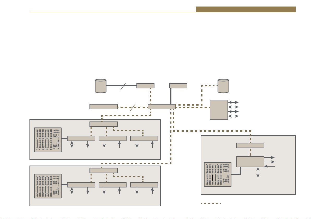
STUDIO 1
Local
Console
STUDIO 2
Console
Audio
Local
Audio
Fig 1-1: AVN Overview Diagram
Hard Disk
Based Audio
Storage
Talkback Units Ethernet Switch
Ethernet Switch
Mix Eng Portal
Mon HP Mic HP Mic
Mix Eng Portal
Mon HP Mic HP Mic
Presenter Guest(s)
Ethernet Switch
Presenter Guest(s)
Portal
Portal
Portal
GPS Antenna
GMC
System Wide Audio
Portals
NEWS ROOM
Console
RAVENNA Capable
Hard Disk
Audio Storage
MADI
SDI
Telephony
Audio (Analogue
or Digital) Inputs & Outputs
Ethernet Switch
AoIP
Mix Eng
Mon
HP
Mic
Local
Audio
1
Page 6

1 AVN – A Guide to Media Networking
sent in packets with an address header to determine the destinations.
It is quite feasible to label a single packet to go to many destinations
(multicasting) and this is handled by the Ethernet switch using IGMP
(Internet Group Management Protocol). This means that a single network
cable can carry many streams of distinct data in either direction. AVN
devices could send audio to hundreds of different destinations and receive
audio from hundreds of different sources on a single Ethernet connection.
An AoIP based system has a positive impact on the installation and
modification of media systems. Each product only requires one cable to
connect it to a network switch and re-routing data is simply arranged in
software, rather than requiring possibly extensive rewiring with new cables,
connectors and routing equipment. The cabling requirements for all devices
is also identical – the ubiquitous Cat6 or Cat5e with RJ45 connectors –
which are easily available and inexpensive, anywhere in the world.
Of course, added flexibility for interconnections comes at a management
cost, and in addition to the packets containing actual data, there a number
of further communication, control and synchronisation protocols that
need to be handled for a fully implemented system. Our AVN products use
several network protocols including: TCP, UDP, HTTP, RTP, RTSP, SDP, SAP,
PTP, mDNS, DNS-SD and IGMP.
AVN in the Audio World - AES67
Audio over IP can be achieved in a variety of ways for example RAVENNA,
Dante, Livewire, and Cobranet. The majority of these existed as noncompatible solutions, but there is now an overarching solution through
the AES67 standard which helps these competing systems to inter-operate.
With the exception of Cobranet from the above, most AoIP solutions
claim compatibility with AES67. There are some choices to be made about
implementation, and some of the outlying methods are not, in general,
being supported, but gradually the use of AoIP in a professional audio
environment is becoming standardised on AES67. AVN products are based
on a RAVENNA solution, and we are committed to providing the extra
protocols to be able to successfully connect with other AES67 products.
Discovery
Discovery is the act of finding other equipment on the local network, and
is essentially an ‘announcement of services supported’ protocol. When a
device is first connected to a network, and periodically after that, it will
send a broadcast message to the network as an “I’m here and can do this”
notification.
We use the Bonjour protocol for Discovery – also known as mDNS, DNS-SD
or Avahi. Bonjour is an Apple implementation and is embedded in their
products. There is a download on our website to use it on PCs. We also have
a small PC application – again downloadable from our website - that can
report on the various Bonjour enabled network products that are available
on your network. SAP is the other major method for discovery used in the
professional audio AoIP world, it is simpler than Bonjour, but with probably
less PC visibility. Our AVN products can also support SAP for discovering
audio streams.
The Discovery mechanism includes an announcement of the services that
the device will support, and in our AVN product range this will include the
RAVENNA AoIP solution, in both default and AES67 modes; and a Sonifex
specific service for network connected GPIO. Audio streams are also
announced using SAP.
Audio Over IP - How it Works
We can discover audio streams in 2 ways. The first method is using Bonjour
to find compatible devices (AES67 or RAVENNA) which provide some audio
streams for us to listen to. At this stage we don’t know what the streams
contain or where they are (in IP address terms). So we interrogate the
device using RTSP to obtain the SDP (Session Description Protocol) packets
for the streams which allows us to find out what streams are available (in
2
Page 7

AVN – A Guide to Media Networking 1
terms of number of channels, sample rates, and sample size) and to what
multicast IP address they are assigned. We can chose a suitable stream and
again using RTSP we express an interest in using the stream – this can be
considered as establishing a connection. AVN products, along with most
other similar devices, continually send their streams regardless of the
numbers of listeners, but it is entirely feasible that some products will only
start sending audio once the RTSP connection has been established.
The second stream discovery method uses SAP (Session Announcement
Protocol). Instead of using RTSP, the SDP packets for streams are announced
on the network using SAP. Essentially we receive the same information via
SAP that we receive using the Bonjour/RTSP method, they are 2 methods
that can be used to achieve the same result.
At this point (whether the data was obtained via Bonjour/RTSP or SAP) we
now know the stream contents, so can accept the RTP audio packets from
the designated multicast address, can de-packetise the data, and then ‘play’
it out. We have successfully connected and received a stream, but that’s not
quite the whole story. Unlike the analogue domain where data is effectively
real time, or the digital audio domain where clocking is embedded in the
data stream, we have no reference between the source device and the
receiving device to ensure that the clocking is synchronous.
Early AoIP solutions used 2 main methods. The first relied on a distributed
wordclock so audio data clocks were generated locally on both devices from
the same source and were essentially synchronous – but this required extra
cabling which cancels out a major benefit of AoIP which is the simplification
of wiring requirements. The second used the incoming buffering as a crude
clock error gauge – so as the buffer got to nearly empty it was assumed that
the local clock was running too quickly and conversely as the buffer got to
nearly full the local clock was running too slowly. This information was used
to either adjust the clock to correct the data flow or, using clever algorithms
to minimise audible artefacts, samples were discarded or added to correct
the error. The downside is that the buffer needed to be considerably
bigger than the size of the data packets, so this increased latency (the gap
between audio being sent by the source and it being played out at the
receiver).
Synchronisation - Using PTPv2
The latest AoIP implementations use the Precision Time Protocol – known
as PTPv2 or the IEEE.1588-2008 standard - to synchronise independent
clocks running in the source and destination. The PTP system was designed
to provide highly accurate real time stamping of IP packets. To achieve
this, the source clocks required a GPS receiver to capture and use the GPS
satellite time information as a reference. These devices are known as Grand
Master Clocks. The AVN-GMC which is part of the Sonifex AVN product
range is designed for the particular requirements of the professional audio
AoIP environment.
In an AoIP environment what we generally need is not the actual time, but
synchronised time, so in small systems most devices can act as a Master
Clock with no requirement for the time stamps to reflect the actual time.
There is a prioritisation method defined in IEEE.1588 that sets the way that
master clocks handle which device is designated as the master clock in a
network system.
There are various flavours of PTP – called profiles – and these determine
the regularity of the various requests and announcements made by and
expected by the Master Clock. There are a number of pre-defined profiles
that have been designed to meet certain requirements
There is also a hierarchical structure available, whereby a Master Clock
supplies signals to what is known as a boundary clock, which in turn
supplies PTP packets to other devices. Many top-end Ethernet switches
have such an option and this has the benefit of reducing network overhead
on both the network infrastructure and on the Master Clock. Usage of PTP
requires a good network infrastructure and really only works across a LAN
where IP packet deliveries are consistent – see the ‘Infrastructure’ section
3
Page 8

1 AVN – A Guide to Media Networking
Ethernet Switch
IP Audio Devices
IP Audio Devices
IP Audio Devices
IP Audio Devices
IP Audio Devices
IP Audio Devices
IP Audio Devices
IP Audio Devices
IP Audio Devices
IP Audio Devices
IP Audio Devices
AVN - GMC
PTP Switch
Ethernet Switch
PTP Switch
for best practice. In solutions where you might want to use AoIP across
a WAN or leased line connection or even broadband, then the 2 ends of
the conversation would need independent Grand Master Clocks that are
synchronised to the common GPS time.
Buffering
AoIP is affected by the packetized and negotiated nature of IP, so we cannot
expect the data to arrive at consistent time intervals. This means that we
need to buffer data at the source device – to fill the designated packet size,
PTPv2 Grandmaster Clock
Cat 5 Cable
Fibre or Cat5e/Cat6
depending on distance
Ethernet Switch
and at the receiver device to allow for the packet nature and the variation
in timing of packets being received. There is a straightforward trade-off
between latency and network overhead, when the packet size is larger, the
buffering requirement increases and therefore latency is higher, but fewer
packets are required so the network overhead is reduced – and vice-versa
for smaller packet sizes. The various arrangements are again known as
profiles and we always support the middle ground ‘Default’ profile as a
norm, with other profiles available according to the device and its design
parameters.
These devices have an internal clock and will source all PTP
time requests from subsequent devices in the network
These 2 devices will have a less accurate
time stamp due to the variation in latency
from the 2 non-PTP switches
Fig 1-2: The AVN Hierarchical Structure Diagram
4
These 6 devices will have an accurate
time stamp as they will receive the time
from the local PTP switch
These devices will have a moderately
accurate time stamp due to the variation
in latency from the single non-PTP switch
Page 9

AVN – A Guide to Media Networking 1
Infrastructure
The infrastructure requirements of an AoIP solution are relatively simple
– cabling, Ethernet Switches, and clock source. Cabling is straightforward
and you should use Cat6 or Cat5e cables with standard pin to pin RJ45
connectors. Ethernet Switches are available with many different capabilities
and the necessity for these depends on the complexity of your network. For
a rough idea of the switch requirements based on the type of installation
see the table below:
No Switch required Just 2 devices connected to each other
10/100 unmanaged switch
or hub
10/100 managed switch with
L3 QoS (DiffServ) and IGMP
Snooping
10/100/1000 managed
switch with L3 QoS (DiffServ)
and IGMP Snooping
10/100/1000 managed
switch with L3 QoS (DiffServ),
IGMP Snooping and
IEEE.1588 transparent time
stamping
10/100/1000 managed
switch with L3 QoS (DiffServ),
IGMP Snooping, and
Boundary Clock
2 or 3 devices with low network overhead
– some devices are 1Gbe only so will need
a faster Ethernet switch
Multiple (<15) devices all with 10/100
connectivity (by definition these should be
low network overhead)
Multiple (<15) devices, some with 1Gbe
connectivity – this is the minimum we
would recommend for a non-laboratory
installation
Multiple (>10) devices, or several devices
with 1Gbe connectivity
Multiple (>10) devices, or several devices
with 1Gbe connectivity and with a number
of intermediate switch elements to the
Master Clock
As a rule we recommend that AoIP networks are kept separate from normal
office networks - most managed switches these days have VLAN capability
and running the AoIP and office on different VLANS would provide sufficient
separation. The nature of office network with file transfers and live
streaming can be network traffic heavy and may affect the successful audio
transmission, and, conversely, office transfers may well be slowed during
periods of high audio connectivity.
This might be an issue if you need to manage or monitor the status of AVN
devices from office PCs. Consequently the higher spec AVN equipment has
2 Ethernet ports, the first for command and control (C & C) and the second
for the AoIP connectivity (and C&C). For AVN devices with only one port
then we suggest using a bridge or router to connect between the office and
AoIP networks, which will minimise the traffic below between them; or use
a second network card, connected to the AoIP network; or attach a laptop
to the AoIP network on occasions where you need to set up or monitor the
AVN devices.
5
Page 10

1 AVN – A Guide to Media Networking
Setting the AVN Product Options
All AVN products will have an embedded web server, which means that you
can use a browser - Chrome, Firefox, Safari, Internet Explorer etc – to access
the devices and check their status, change settings, or update firmware.
The following web pages, with minor differences to suit specific products
requirements, and the explanations, are applicable to all AVN products.
To access the embedded web server, the unit needs to be connected to a
network via the network ports on the rear panel – where more than 1 port
is available either port may be used and in this case, generally, the upper
port is the general access Ethernet port and the lower port is the audio over
IP (AoIP) port.
By default, both ports are set to static address mode with the upper port
or only port IP address set to 192.168.0.100 and the second, lower port
IP address set to 192.168.1.100 with both ports using a subnet mask of
255.255.255.0.
Ethernet Port IP Address: 192.168.0.100
AoIP Port IP Address: 192.168.1.100
Subnet Mask: 255.255.255.0.
If the network address mode for the port to be used has been set to
dynamic, the unit will attempt to acquire an IP address from a DHCP server
or auto configuration if no DHCP server is found. Where the unit has a front
panel with an OLED screen and rotary navigation control then the current
IP address of these ports can be accessed by going to the main menu and
selecting ‘System Info’ for details.
If a port has yet to acquire an IP address or has failed to link, the
corresponding IP address and subnet mask will show 0.0.0.0.
Once the IP address of the required port is known, simply type this into
the address bar of a web browser. The Information page of the connected
product will be displayed. This is the default page and will always be
displayed first when connecting to the embedded web server. Each page of
the web server shows the device identifier in the upper right hand corner,
with the unique host name underneath. This makes it easier to identify
the connected device, especially when configuring multiple units at the
same time. The right hand side of each page has a brief help section that
describes the content of each section.
6
Page 11
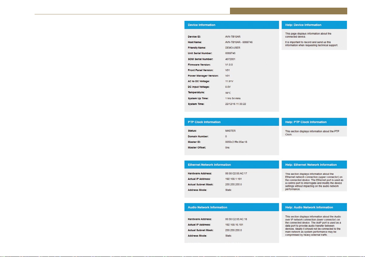
Information Page
This page will show general information about the device – this is a
typical page for connected equipment. The information may change
from product to product, according to the power supply used by the
device and the number of Ethernet ports available.
Device Information shows the identifiers for the device, the serial
numbers of the relevant components, the firmware versions of
software running on the device, the voltage status, a temperature
reading and system timers.
PTP Clock Information provides information about the source of the
PTP clock that is used to synchronise audio play-out. The source can
be local (MASTER) or remote (SLAVE) and the domain and ID will
identify the source and type. The offset quantifies the accuracy of
the internally generated clock with respect to the source. All AVN
devices can be a MASTER PTP source, but we would recommend
that the priorities are set up so that the MASTER is a GMC or a
higher powered central unit.
Network Information is displayed for each Ethernet port fitted and
shows the MAC address and the currently used IP settings of that
port.
AVN – A Guide to Media Networking 1
Fig 1-3: The Information Page
7
Page 12

1 AVN – A Guide to Media Networking
Network Settings
• Friendly Name – The friendly name is a local name that identifies the
unit on the network. It is a good idea to assign a user name or location
as this is easily recognised by other users. The default friendly name is
the host name which is made from the device ID and the 7 digit product
serial number i.e. AVN-TB10AR-1234567. The host name is unique, but
the friendly is user settable and does not have to be unique – though,
generally, this is a GOOD idea. When the device is addressed across the
internet the host name is used, but for user interaction the host name is
aliased to the device’s friendly name to ease identification.
• Address Mode – Each network port has its own independent address
mode which determines how the port obtains its IP address. When set
to dynamic, the unit will attempt to acquire an IP address automatically
from either a DHCP server or via auto configuration if no response from
a DHCP server is received. The actual IP address will be shown on the
device information page or in the front panel menu if an OLED screen is
fitted to the device. When static mode is used, the IP address and subnet
mask values entered will be assigned to the corresponding network port.
• Static IP Address – This is the IP address that will be assigned to the
corresponding network port when static address mode is selected. It is
important to ensure that this IP address is not currently in use on the
network. This value is not used when the address mode is dynamic.
• Static Subnet Mask – This is the subnet mask that will be used for the
corresponding network port when static address mode is selected. This
value is not used when the address mode is dynamic.
If any of the network configuration options are changed and submitted,
the unit will automatically restart to implement the new settings. If the IP
address of the network port that is currently being used to access the web
server is changed, a new connection will need to be made once the unit has
restarted. Otherwise, the new page will be shown automatically once the
restart is complete.
Fig 1-4: Network Settings Page
8
Page 13

Network Defaults
Friendly Name: DDDDDD-xxxxxxx
Where DDDDDD is the device type
and xxxxxxx is the product serial
number
Ethernet Port:
Address Mode: Static
Static IP Address: 192.168.0.100
Static Subnet Mask: 255.255.255.0
AoIP Port or shared port: (where fitted)
Address Mode: Static
Static IP Address: 192.168.1.100
Static Subnet Mask: 255.255.255.0
AVN – A Guide to Media Networking 1
9
Page 14

1 AVN – A Guide to Media Networking
PTP Profiles
The PTP Profiles web page show the currently selected PTP profile and
allows the parameters in each profile to be edited. Similar changes can be
made from the front panel when an OLED display and rotary navigation
control is present.
Active Profile – There are 3 PTP profiles available: Default, AES Media, and
Custom. This drop down list selects which of the profiles will be active.
DSCP – The DSCP or Differentiated Services Code Point value is used by
Diffserv to control the precedence of outgoing PTP packets. Network
hardware can use this value to ensure PTP data has higher priority over
other network traffic. See table on page 12 – DSCP Names & Their
Corresponding IP Precedence for more information.
Profile Select – This drop down list selects the profile to view and change
settings. All of the available profiles can be edited.
Reset to Defaults – Selecting this checkbox and pressing the submit button
resets the selected profile to the default settings for that profile.
Delay Mechanism – This selects the method for calculating and maintaining
the clock synchronisation communication delay between master and
slave devices. Both P2P (Peer to Peer) and E2E (End to End) methods are
supported. The best method for a particular installation will depend on the
type of network hardware used. If all the switches are known to be IEEE
1588 capable, P2P should be used. Otherwise it is best to use E2E.
Announce Interval – This is the rate at which the announce message is sent,
one per the selected time. The announce message forms part of the Best
Mater Clock Algorithm (BMCA) and contains the properties of the clock
which sends it. If a device receives an announce message from a better
clock, it will enter the slave state.
10
Fig 1-5: PTP Profiles Page
Page 15

AVN – A Guide to Media Networking 1
Announce Timeout – This is the time the unit will wait for an announce
message and is a multiple of announce intervals. If no announce messages
are received within the timeout interval, the unit will assume the role of
grandmaster.
Sync Interval – This is the rate at which the sync message is sent, one per
the selected time. The sync and follow up messages are sent from the
master to the slave to determine the difference in clock frequency. This
information is used in conjunction with the network delay to synchronise
the clocks.
Delay Req Interval – This defines the rate at which a slave clock sends delay
request messages to the master. The delay request message allows a slave
device to calculate the network delay from the slave to the master. This
option is only valid when using the E2E delay mechanism.
Peer Delay Req Interval – This is the rate at which a device exchanges peer
delay measurement messages. This allows each unit to track the network
delays between itself and its connected neighbours. This option is only valid
when using the P2P delay mechanism.
Priority 1 & Priority 2 – These values define a precedence setting used
by the best master clock algorithm when selecting a grandmaster clock.
Priority 2 defines a fine tune setting when multiple clock sources have
similar ordering criteria.
Domain – This defines the group of PTP devices that the unit will
communicate with.
Slave Only – This option limits the unit to being a slave PTP clock only.
PTP Profiles Defaults
Active Profile: Default
DSCP: AF PHB
Default Profile:
Delay Mechanism: E2E
Announce Interval: 2 secs
Announce Timeout: 3 secs
Sync Interval: 1 sec
Delay Req Interval: 1 sec
Peer Delay Req Interval: 1 sec
Priority 1: 128
Priority 2: 128
Domain: 0
Slave Only: Disabled
11
Page 16
1 AVN – A Guide to Media Networking
AES Media Profile:
Delay Mechanism: E2E
Announce Interval: 2 secs
Announce Timeout: 3 secs
Sync Interval: 1/8 sec
Delay Req Interval: 1 sec
Peer Delay Req Interval: 1 sec
Priority 1: 128
Priority 2: 128
Domain: 0
Slave Only: Disabled
Custom Profile:
Delay Mechanism: E2E
Announce Interval: 2 secs
Announce Timeout: 3 secs
Sync Interval: 1 sec
Delay Req Interval: 1 sec
Peer Delay Req Interval: 1 sec
Priority 1: 128
Priority 2: 128
Domain: 0
Slave Only: Disabled
Slave Only: Disabled
DSCP Name DS Field Value IP Precedence (Description)
CS0 0 0: Best effort
CS1, AF11-AF13 8, 10, 12, 14 1: Priority
CS2, AF21-AF23 16, 18, 20, 22 2: Immediate
CS3, AF31-AF33 24, 26, 28, 30
3: Flash (mainly used for voice
signalling)
CS4, AF41-AF43 32, 34, 36, 38 4: Flash Override
CS5, EF PHB 40, 46 5: Critical (mainly used for RTP)
VOICE ADMIT 44
5: Critical (uses Call Admission
Control)
CS6 48 6: Internetwork Control
CS7 56 7: Network Control
Table 1-1: DSCP Names & Their Corresponding IP Precedence
12
Page 17
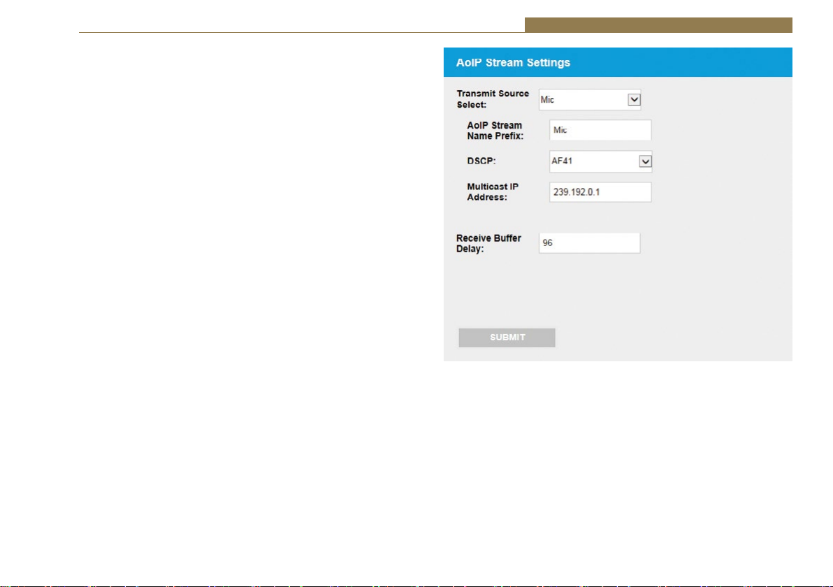
AoIP Streams Web Page
The AoIP Streams page shows the current configuration of the AoIP
transmit and receive options. This allows the user to select the various
output streams available on the device and edit their settings. This shows
a typical page, but the options may vary according to the actual device in
question
Transmit Source Select – There may be any number of streams that a
device can provide. This drop down list selects the transmit source to view
and edit.
AoIP Stream Name Prefix – The AoIP stream name prefix forms part of
the AoIP stream name which will be displayed on remote devices when
searching for AoIP streams. This stream name is comprised of the AoIP
stream name prefix set here for the selected transmit source, and the
intercom name, for the AVN-TB product range. For example, if the default
input 1 AoIP stream name prefix “Input1” is used, and the intercom name is
set to “DEMO-USER”, the advertised AoIP stream name would be “Input1@
DEMO-USER”. Often the prefixes are preset and not editable, in which case
the stream name will be displayed as a fixed string.
DSCP – The DSCP or Differentiated Services Code Point value is used by
Diffserv to control the precedence of outgoing AoIP data packets for the
selected transmit source. Network hardware can use this value to ensure
audio data has higher priority over other network traffic. See table on
page 12 – ‘DSCP Names & Their Corresponding IP Precedence’ for more
information.
Multicast IP Address – The multicast IP address is the IPv4 multicast
destination address for the selected transmit source. Remote network
devices that are configured to receive this source, will use this IP address to
access the audio data. It is important to ensure that the IP address entered
here is unique on the network. No two AoIP stream sources can share the
same multicast IP address.
AVN – A Guide to Media Networking 1
Fig 1-6: The AoIP Streams Web Page
AES67 requires audio multicast streams to be within the ‘administratively
scoped range’, which is restricted to 239.0.0.0 to 239.255.255.255.
Our recommendation to avoid address conflict is to setup the unit to use
addresses derived from the current IP address set for that port and a
session count. So if the AoIP port has an address of 192.168.123.45 then
the multicast addresses should be of the form 239.s.123.45 where s is the
session count. The session count ‘s’ is simply a number that is incremented
for every AoIP stream that the user creates.
13
Page 18
1 AVN – A Guide to Media Networking
This means the first stream should have a multicast address of
239.0.123.45, the next stream should be 239.1.123.45 and so on. Where
the unit creates non-audio streams (eg metering info) then the full range
of multicast addresses are available (224.0.0.0 to 239.255.255.255) and
it makes sense to use a first octet outside the AoIP value of 239 so for
instance 238.0.123.45.
At all times it is important to recognise that other equipment on the
network may not use the same rules and so the user will need to be fully
aware of such equipment, and its IP addresses, before choosing any IP
address for AVN equipment.
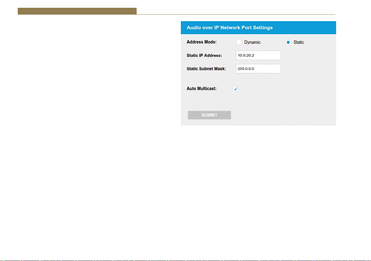
Auto Multicast - Where ‘Auto Multicast’ is available in the ‘AoIP Network
Port Settings’, enabling this will automatically generate the Multicast IP
addresses for the transmit AoIP streams. This option is enabled by default.
Since we use the default of 192.168.0.100 and 192.168.1.100 for the IP
addresses of the Ethernet and AoIP ports respectively, for units that have a
fixed number of sessions the Multicast address is 239.x.1.100 - where x is
the session number.
For units that have dynamic sessions, the Multicast address is 239.x.y.z
- where x is the session number, y and z are the 3rd and 4th octets of
the IP address respectively. For example if the unit’s IP address is set to
192.168.16.200 the sessions will be created with the default multicast
address of 239.x.16.200
Note that when this option is enabled, changing of the session addresses
is NOT allowed. This option is only active while the addressing mode of
AoIP port of the device is set to ‘static’. When in dynamic mode this option
is ignored and the session addresses can be changed. If the addressing
mode is then changed back to static this will in turn revert the session
addresses back to their defaults as per the above rules.
Fig 1-7: The Auto Multicast Option
Auto Multicast Summary - When the ‘Auto Multicast’ option is enabled
and the addressing mode is ‘static’ the session addresses will always be in
the form of 239.x.y.z
where x is the session number, y and z are the 3rd and 4th octets of the
AoIP port’s IP address respectively.
14
Page 19

References and Standards
Free download from datatracker.ietf.org – search by RFC number
IP - Internet Protocol. RFC 791
UDP - User Datagram Protocol. RFC 768
TCP - Transmission Control Protocol. RFC 793
IGMP - Internet Group Management Protocol (Version2).
RFC 2236
DHCP - Dynamic Host Configuration Protocol. RFC 2131
Auto-IP - Dynamic Configuration of IPv4 Link-Local Addresses.
RFC 3927
RTSP - Real Time Streaming Protocol. RFC 2326
SDP - Session Description Protocol. RFC 4566
RTP - A Transport Protocol for Real Time
Applications. RFC 3550
RTCP - Real Time Transport Control Protocol. RFC 3550
mDNS - Multicast DNS. RFC 6762
DNS-SD - DNS-Based Service Discovery. RFC 6763
HTTP/1.1 - Hypertext Transfer Protocol. RFC 2616
URL - Uniform Resource Locators. RFC 1738
DiffServ - Definition of the Differentiated Services
in IPv4 and IPv6 headers. RFC 2474
Configuration Guidelines for DiffServ
Service Classes.RFC 4594
AVN – A Guide to Media Networking 1
Purchase from standards.IEEE.org
PTPv2 - IEEE Standard for a Precision Clock Synchronization
Protocol for Networked Measurement and Control
Systems. IEEE 1588-2008
Purchase from www.aes.org/publications/standards/
AES67-2015 - AES standard for audio applications of networks High-performance streaming audio-over-IP
interoperability
View at www.ravenna-network.com/about-ravenna/resources
RAVENNA Network Principles 1.0
RAVENNA Network Requirements 0.2
RAVENNA and AES67 1.0
Sonifex & Ember+ Apps
www.sonifex.co.uk/downloads/servdisc.zip
www.sonifex.co.uk/downloads/tinyEmber.zip
15
Page 20

www.sonifex.co.uk
t:+44 (0)1933 650 700
f:+44 (0)1933 650 726
sales@sonifex.co.uk
 Loading...