

Page 1
User's Manual
LVN-020-UM-01-EN
Page 2

FCC regulation warning (for USA)
Note: This equipment has been tested and found to comply with the limits for a Class B digital device, pursuant to
part 15 of the FCC Rules. These limits are designed to provide reasonable protection against harmful interference in
a residential installation. This equipment generates, uses and can radiate radio frequency energy and, if not installed
and used in accordance with the instructions, may cause harmful interference to radio communications. However,
there is no guarantee that interference will not occur in a particular installation. If this equipment does cause harmful
interference to radio or television reception, which can be determined by turning the equipment o and on, the user is
encouraged to try to correct the interference by one or more of the following measures:
—Reorient or relocate the receiving antenna.
—Increase the separation between the equipment and receiver.
—Connect the equipment into an outlet on a circuit dierent from that to which the receiver is connected.
—Consult the dealer or an experienced radio/TV technician for help.
Legal disclaimers
Sonicware Inc. (hereafter, “SONICWARE” strives to assure that this document is as accurate and current as possible,
but will bear no responsibility for any compensation, claims or losses due to content included in this document.
Moreover, information in this document could be changed without notice. SONICWARE retains the right to change
product specications and programs at any time. SONICWARE will bear no responsibility for any errors depicted in this
document. SONICWARE will bear no responsibility for any losses resulting from the use of this information, functions or
performance, regardless of contracts, lack of caution or other conduct.
Copyrights and registered trademarks
• SONICWARE is a registered trademark of Sonicware Inc.
• MIDI is a registered trademark of the Association of Musical Electronics Industry (AMEI).
• Other company names, product names, standard names and registered trademarks in this document are the
property of their respective owners.
• All the trademarks and registered trademarks in this document are not intended to violate the copyrights of their
owners, but rather are included for the purpose of identication only.
• Recording from copyrighted sources, including audio les, CDs, records, videos, tapes, broadcasts,
streamed content and works of art, without permission of the copyright holder for any purpose
other than personal use is prohibited by law.
• Sonicware Inc. will not assume any responsibility related to infringements of copyrights.
Important safety precautions
You must read the following precautions in order to use the product safely and prevent accidents.
WARNING: Failure to follow these precautions could result in serious harm to the user or even
death.
• Operation using an AC adapter
Do not do anything that could exceed the ratings of outlets and other electrical wiring equipment.
Disconnect the AC adapter with USB output from the outlet when lightning occurs and when not in use for a
periods of time.
• Operation using batteries
Use-commercially available 1.5V AA batteries.
Carefully read the precautions of the batteries being used.
2
Page 3

Be sure to insert the batteries with +/ - ends oriented correctly.
Do not use new and old batteries together. Do not use batteries of dierent types together.
Remove the batteries when they will not be used for a long time.
If a leak occurs, thoroughly wipe the battery compartment and battery terminals to remove the leaked uid.
• Do not open the case and disassemble or modify the product.
• Do not drop, strike or apply excessive force to the unit.
• Did not put liquid on or in the unit.
• Do not put foreign objects into the case.
• Do not use at a loud volume. Doing so could generate loud sounds that might lead to hearing loss.
• When transporting this unit, use the individual packing box and cushioning material that it came with when
purchased new.
• When the unit is powered on, do not wrap it in cloth, plastic or other materials.
• Do not step on or apply pressure to the power cord.
• Do not use in the following environmental conditions. Doing so could cause malfunctions.
Locations with direct sunlight, environments that exceed 40ºC, or near stoves and other heat sources
Locations with extremely low or high temperatures
Locations with extremely high humidity or where the product could become wet
Locations with frequent vibrations or much dust or sand
• If the unit becomes broken or malfunctions, immediately turn the power o and stop using it.
Usage Precautions
Failure to follow these precautions could cause injury to the user and physical damage.
• When connecting cables or turning the unit on or o, minimize the input levels of connected devices or turn them
o.
• Cleaning
If the screen or the case become dirty, wipe them gently with a soft cloth.
Do not use chemicals, including alcohol, benzene, thinner or cleansers.
If a soft dry cloth is not enough to clean the unit, wipe them with a slightly damp cloth that has been wrung out
well.
Do not turn the power on until the unit is completely dry.
3
Page 4

Contents
Preparing to play ……………………………………………………………………… 5
Part names …………………………………………………………………………… 5
Connecting …………………………………………………………………………… 5
Preparing for startup ……………………………………………………………… 6
Starting up …………………………………………………………………………… 6
Turning the unit o ………………………………………………………………… 6
Sound memories, tracks, and patterns ……………………………………… 6
Tracks …………………………………………………………………………………… 6
Basic operations ……………………………………………………………………… 7
Adjusting the overall volume …………………………………………………… 7
Changing the octave range ……………………………………………………… 7
Basic knob operation ……………………………………………………………… 7
Selecting and playing tracks …………………………………………………… 7
Changing the velocity ……………………………………………………………… 7
Sweeping notes while playing …………………………………………………… 7
Holding notes ………………………………………………………………………… 7
Changing step button parameters ……………………………………………… 7
Track settings ………………………………………………………………………… 8
Selecting tracks ……………………………………………………………………… 8
Clearing all notes in a track ……………………………………………………… 8
Restoring track sound settings to the last saved state ………………… 8
Changing the synth engine ……………………………………………………… 8
Adjusting synth engines …………………………………………………………… 8
Changing the lter type …………………………………………………………… 9
Changing the lter cuto frequency …………………………………………… 9
Adjusting the lter envelope ……………………………………………………… 9
Changing the LFO type …………………………………………………………… 9
Changing the LFO starting delay ……………………………………………… 9
Adjusting the LFO speed …………………………………………………………10
Adjusting the amount of LFO eect on pitch ………………………………10
Adjusting the amount of LFO eect on lter cuto ………………………10
Changing track note playback probability ……………………………………10
Setting the level of track output sent to the eect ………………………10
Changing the sweep amount ……………………………………………………10
Changing the sweep speed ………………………………………………………10
Changing the sweep curve ……………………………………………………… 10
Changing track pitch by semitone (transposing) …………………………11
Changing the voice mode …………………………………………………………11
Changing the legato speed ………………………………………………………11
Changing the arpeggiator type …………………………………………………11
Changing the track swing amount ………………………………………………11
Changing the track release and gate time ……………………………………11
Changing track levels ………………………………………………………………12
Adjusting track panning ……………………………………………………………12
Muting tracks …………………………………………………………………………12
Setting track MIDI channels ………………………………………………………12
Copying tracks ……………………………………………………………………… 12
Pattern playback and settings ……………………………………………… 13
Pattern playback …………………………………………………………………… 13
Selecting patterns ………………………………………………………………… 13
Changing pattern volume …………………………………………………………13
Selecting multiple patterns and playing them in order
(chain playback) ……………………………………………………………………13
Saving patterns ……………………………………………………………………… 13
Initializing patterns …………………………………………………………………14
Reloading patterns …………………………………………………………………14
Changing the eect type …………………………………………………………14
Changing eect parameters ………………………………………………………14
Setting the sequencer mode ……………………………………………………14
Setting pattern BPM ……………………………………………………………… 15
Setting the global BPM ……………………………………………………………15
Setting the BPM mode ……………………………………………………………15
Adjusting the metronome volume ………………………………………………15
Changing pattern names …………………………………………………………15
Synchronizing the tempo with another
device connected to the SYNC IN ………………………………………………16
Synchronizing tempo with an ELZ_1 or
Pocket Operator (PO) ………………………………………………………………16
Examples of synchronization connections with
external devices ………………………………………………………………………16
Track sequencing ………………………………………………………………… 17
Step recording ……………………………………………………………………… 17
Copying and pasting steps during step recording …………………………17
Automatically advancing steps during step recording
(auto step mode) …………………………………………………………………… 17
Recording in real time ………………………………………………………………17
Directly inputting notes on steps ………………………………………………18
Enabling the input of longer notes (tied notes) ……………………………18
Recording parameter locking automation ……………………………………18
Recording parameter locking automation in real time ……………………18
Recording sound locking automation to steps………………………………18
Turning parameter locking automation on/o ………………………………18
Initializing parameter lock automation …………………………………………19
Clearing note and parameter lock automation data ………………………19
Changing the track length ………………………………………………………… 19
Changing the note length of a single step …………………………………19
Setting the track playback unit used during
random playback ……………………………………………………………………19
Sound editing ………………………………………………………………………… 20
Editing sounds ………………………………………………………………………20
Clearing sounds ………………………………………………………………………20
Copying sounds ………………………………………………………………………20
Changing sound names ……………………………………………………………21
Changing sound bank names ……………………………………………………21
Capturing synth engine sounds (capture mode) ……………………………21
Creating sounds with operators using the editing overlay ……… 22
Selecting the operator to edit ……………………………………………………22
Muting operators …………………………………………………………………… 22
Setting connection levels and feedback between operators …………… 22
Setting operator ratios ……………………………………………………………22
Setting operator levels ……………………………………………………………23
Setting operator detuning …………………………………………………………23
Setting operators to xed mode …………………………………………………23
Setting the frequency when in xed mode ……………………………………23
Setting operator envelopes ………………………………………………………23
Setting operator envelope curves ……………………………………………… 24
Turning the pitch envelope on/o ………………………………………………24
Setting the pitch envelope ……………………………………………………… 24
Setting the operator keyboard gain scaling depths
(left/right) …………………………………………………………………………… 24
Setting the operator keyboard gain scaling curves
(left/right) ………………………………………………………………………………25
Setting the operator keyboard gain scaling position ……………………… 25
Setting operator velocity sensitivity ……………………………………………25
Setting the operator keyboard time scaling …………………………………25
Setting operator to mixer connection levels …………………………………26
Setting the mixer output level ……………………………………………………26
Selecting algorithms and setting operator connections …………………26
Changing the voice mode and playing during sound editing …………… 27
External input settings ………………………………………………………… 28
Changing the FX send amount ………………………………………………… 28
Changing the gain ……………………………………………………………………28
Setting mono/stereo ………………………………………………………………28
MIDI settings ………………………………………………………………………… 29
Setting track MIDI channels ………………………………………………………29
Setting the MIDI channels for pattern parameters ………………………… 29
Setting the MIDI channel for accessing the active track
(auto channel) …………………………………………………………………………29
Setting the output channel ………………………………………………………29
Setting the program change channel …………………………………………29
Turning control change transmission on/o …………………………………29
Turning MIDI clock output on/o ………………………………………………29
Setting MIDI OUT ……………………………………………………………………29
Setting MIDI command receipt and transmission …………………………29
Turning active sensing transmission on/o …………………………………30
Turning active sensing reception on/o ………………………………………30
Turning program change transmission on/o
Turning program change reception on/o …………………………………… 30
Saving and loading user data ………………………………………………… 31
Exporting pattern data …………………………………………………………… 31
Exporting sound data ………………………………………………………………31
Exporting sound banks …………………………………………………………… 31
Importing sound data ………………………………………………………………31
Importing sound banks …………………………………………………………… 31
Backing up user data ………………………………………………………………31
Restoring user data …………………………………………………………………32
System settings …………………………………………………………………… 33
Setting the automatic power o function ……………………………………33
Setting the battery type …………………………………………………………… 33
Setting the master tuning …………………………………………………………33
Setting the clock source ………………………………………………………… 33
Setting SYNC IN polarity …………………………………………………………33
Setting SYNC OUT polarity ………………………………………………………33
Setting knob movement behavior ………………………………………………33
Enabling/disabling speaker output ……………………………………………34
Setting the headphone gain ………………………………………………………34
Checking the system version ……………………………………………………34
Restoring to factory default settings (factory reset) …………………… 34
Updating the rmware ………………………………………………………………34
Appendix ……………………………………………………………………………… 36
………………………………30
4
Page 5
Preparing to play
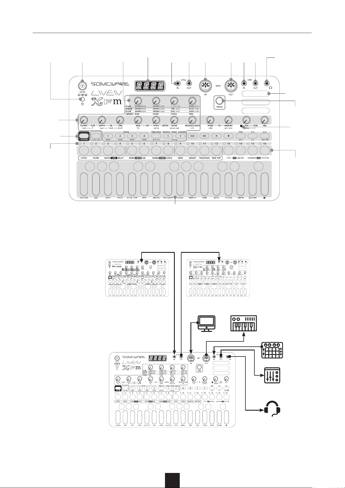
Part names
POWER
switch
Knobs
Buttons
Step LEDs
DC9V
jack
Main knobs
1–4
Display SYNC
IN
Keyboard
SYNC
OUT
MIDI
IN
MIDI
OUT
LINEINLINE
OUT
Headphone
jack
Speaker
VALUE
knob
TEMPO
LED
Step
buttons
Connecting
Note : Use cables that are 3 m or shorter.
5
Page 6
Preparing to play
Preparing for startup
① Connect an AC adapter that conforms to the
specifications (9V output, 1 A or more, EIAJ-03
standard, 1.7mm inner diameter, 4.75mm outer
diameter, center +) to the DC9V jack on the LIVEN
XFM.
(Always use an AC adapter with these specica
tions. Using an AC adapter with dierent specications could cause damage.)
② Plug the AC adapter into an outlet.
• To power the LIVEN XFM using batteries, open the
cover on the bottom and install 6 AA batteries.
• BT.LO will appear on the display at a regular interval
if the remaining battery charge is low.
• BT.LO will appear on the display when starting up if
the remaining battery charge is low.
• When BT.LO appears, replace the batteries right
away.
banks of 16.
Up to 128 patterns can be saved in 8 banks of 16.
When shipped new from the factory, preset sounds
and sequences are saved in some sound memories
and patterns.
• If a parameter being shown is the same as the
-
original, a dot will appear at the bottom right of the
display.
Tracks
Patterns have four tracks, and dierent sounds can
be set for each track. In addition, sequences can be
created for each track.
• A maximum of six notes can be generated
simultaneously (six-voice polyphony).
• If the maximum number of simultaneous notes is
exceeded, notes will be turned off starting with
tracks with the lowest priority. (If notes have been
released, however, these notes will be turned off
before other notes using the same track priority
order.)
• The track priority order from high to low in is 4 > 3
> 2 > 1.
Starting up
① Press and hold the POWER switch to turn on the
LIVEN XFM.
Turning the unit o
① Press and hold the POWER switch to turn off the
LIVEN XFM.
• Sound settings that have been edited will be lost
when the power is turned off, so save them as
necessary beforehand.
Sound memories, tracks, and patterns
Sound memories save FM synthesizer sound
settings.
Tracks save the sound memories they use, filter
and other tone settings, sequences and other
performance data.
Patterns save data for their four tracks and other
pattern-related settings, including tempo and eects.
Up to 512 sound memories can be saved in 32
6
Page 7
Basic operations
This section explains basic operations.
Adjusting the overall volume
① Turn the
• The level is shown on the display.
• This can be adjusted from -∞ to +6 dB with 0 dB
as the middle value (63–64).
• The setting range is 0 – 127.
VOL knob.
Changing the octave range
① Press the button to lower the
button to raise the octave by
one.
• The octave can be raised or lowered by ± 3 from
the standard octave.
• Depending on the octave, the
cursor button changes to green ( ± 1), orange ( ±
2) or red ( ± 3). (They are unlit when the octave has
not been changed.)
• The octave is saved for each track.
Basic knob operation
Turning a knob will change the parameter printed in
uppercase letters.
Turning a knob while pressing the
parameter printed in lowercase letters.
will change the
• The parameter value is shown on the display.
• The setting range is 0 – 127.
Sweeping notes while playing
① While pressing the func button, press the
button to sweep down or the
button to sweep up.
• Press the button again to turn
sweep o. (The button will become unlit.)
② Play the keys.
• Patterns recorded with sweep active will also sweep
during pattern playback.
Holding notes
① Play a key while pressing the button to hold the
note.
• Press the same key again to stop holding it.
• Press the
button to stop holding notes for the selected
track.
• During pattern playback, stopping will stop holding
all notes.
button while pressing and holding the
• status can be held by pressing the while
pressing the
holding.)
. (Press the again to stop
Selecting and playing tracks
① Press a track button to select it. (The selected track
button will light red.)
The buttons of tracks that are not selected light
green (or orange when muted).
Changing the velocity
① While pressing shift, turn the
velo knob.
Changing step button parameters
① While pressing the button, press the desired step
button.
• The current setting value will be shown.
• Sequence mode settings will be reflected
immediately.
② Press the step button repeatedly or turn the
VALUE knob to change the parameter value.
• The parameter value is shown on the display.
• The
7
VALUE knob cannot be used with STUTTER
and RANDOM.
Page 8
Track settings
This section explains how to adjust track settings,
including for the synth engine, filter, LFO, envelope
generator (EG) and eects.
Selecting tracks
① Press the desired TRACK button.
The selected track button lights red.
The buttons of tracks that are not selected light
green (or orange when muted).
The rst 16 steps of the track sequence are shown
by the step LEDs.
• The track number is shown on the display.
• The parameters shown in the blue areas on the top
of the unit can be controlled separately for each
track.
Clearing all notes in a track
① While pressing and holding , press a TRACK
button to clear the notes on that track.
• The type of data to be cleared will be shown on the
display.
② Turn the
③ Press the
• CLR will appear on the display.
VALUE knob to select NOTE.
button.
• CLR will appear on the display.
• When track sound settings are reloaded, the sound
is restored to its last saved state.
• The following parameter changes are cleared.
1. All synth engine settings
2. Voice mode
3. All lter settings
4. All sweep settings
5. Track level
6. Panning
7. FX send level
8. All LFO settings
9. RELEASE & GATE
10. Swing
Changing the synth engine
① While pressing the button, press the button
to select the synth engine.
• The synth engine name appears on the display.
• This can also be changed with the
• Four types of synth engines can be chosen.
1. X-LAB (XLAB on display): This synth blends two
sounds to create a new sound.
2. XFORM (XFRM on display): This synth switches
between two sounds after the set amount of
time.
3. X-LFO (XLFO on display): This synth morphs
cyclically through two sounds.
4. LIBRARY (LIB on display): This simple synth plays
selected sounds.
VALUE knob.
Restoring track sound settings to
the last saved state
① While pressing and holding , press the TRACK
button for the track to be restored to saved sound
settings.
• The type of data to be cleared will be shown on the
display.
② Turn the
③ Press the
VALUE knob to select SND.
button.
Adjusting synth engines
① Turn
engine parameter list" on p.36.)
• Parameter values are shown on the display.
• Turn these knobs while pressing and holding the
• See the preset sound list (separate le) for details
8
main knobs 1–4. (See "Table 1. Synthesizer
button to adjust other synth engine parameters.
about the preset sounds.
Page 9
Track settings
Changing the lter type
① While pressing the button, press the button
to select the type.
The
• The lter type name is shown on the display.
• This can also be changed with the VALUE knob.
• Ten types of lters can be selected.
1. LPF./\ (LP/\ on display): This filter cuts high
2. LPF.|\_ (LP|\_ on display): This filter cuts high
3. LPF./|_ (LP/|_ on display): This filter cuts high
4. HPF./\ (HP/\ on display): This filter cuts low
5. HPF.|\_ (HP|\_ on display): This filter cuts low
6. HPF./|_ (HP/|_ on display): This filter cuts low
7. BPF./\ (BP/\ on display): This filter only allows
8. BPF./|_ (BP/|_ on display): This lter only allows
9. BPF.|\_ (BP|\_ on display): This lter only allows
10. OFF: No lter is used.
LED will light.
frequencies using an envelope with attack and
decay.
frequencies using an envelope with decay.
frequencies using an envelope with attack.
frequencies using an envelope with attack and
decay.
frequencies using an envelope with decay.
frequencies using an envelope with attack.
frequencies in a specic range to pass using an
envelope with attack and decay.
frequencies in a specic range to pass using an
envelope with decay.
frequencies in a specic range to pass using an
envelope with attack.
Changing the lter cuto frequency
① Turn the
• The parameter value is shown on the display.
• The setting range is 0 – 127.
• The frequency can be changed in a range of 70 –
21600 Hz.
CUTOFF knob.
• The setting range is 0 – 127.
• The resonance can be changed in a range of 0.1 –
10.
• For BPF, the bandwidth can be changed in a 0.1 –
2.0 octave range.
Adjusting the lter envelope
① Turn the
• The parameter value is shown on the display.
• The setting ranges are - 63 – +63 for DEPTH and
0 – 127 for TIME.
• The time can be changed in a range of 27 ms – 40 s.
• For LPF./\, HPF/\ and BPF./\, TIME changes the
attack and the decay.
• For LPF.|\_, HPF.|\_ and BPF.|\_, TIME changes the
decay.
• For LPF./|_, HPF./|_ and BPF./|_, TIME changes the
attack.
• Filters of the same type (e.g. LPF./\ and LPF.|\_)
share DEPTH and TIME settings.
DEPTH and TIME knobs.
Changing the LFO type
① While pressing the button, press the
button, and select the LFO shape.
• The type is shown on the display.
• This can also be changed with the
• Eight types of lters can be selected.
1. SINE (sine wave)
2. SQAR (square wave)
3. TRI (triangle wave)
4. SAW (sawtooth wave)
5. R.SAW (reverse sawtooth wave)
6. RNDM (random wave)
7. LOG (logarithmic wave)
8. R.LOG (reverse logarithmic wave)
VALUE knob.
Adjusting the lter resonance
① While pressing the button, turn the
• The parameter value is shown on the display.
• For BPF, this adjusts the width of the band.
reso knob.
Changing the LFO starting delay
① While pressing the button, press the
button, and change the delay time.
• The time is shown on the display.
• This can also be changed with the
9
VALUE knob.
Page 10
Track settings
• The time can be changed in a range of 0 – 8000
ms.
Adjusting the LFO speed
① Turn the
• The parameter value is shown on the display.
• The setting range is 0 – 127.
• The frequency can be changed in a range of 0.1 –
30 Hz.
RATE knob.
Adjusting the amount of LFO eect on
pitch
① Turn the
• The parameter value is shown on the display.
• The setting range is 0 – 127.
• This changes it in a range of - 2 – +2 octaves.
PITCH knob.
• The parameter value is shown on the display.
• The setting options are OFF and 1 – 127.
• This changes it in a range of 0 – 100%.
• For insert type eects, OFF enables direct output,
while other settings disable direct output, sending
the signal to the eect at 0 dB.
Changing the sweep amount
① While pressing the button, press , and
set the sweep amount.
• The sweep amount is shown on the display.
• This can also be changed with the
• T h e
semitones or 1 – 2 octaves.
• Pressing the
semitone, 1 octave and 2 octave values.
amount can be set to 1 – 11
button cycles through 1
VALUE knob.
Adjusting the amount of LFO eect on
lter cuto
① Turn the
• The parameter value is shown on the display.
• The setting range is 0 – 127.
• This changes it in a range of 0 – 100%.
FILTER knob.
Changing track note playback probability
① While pressing the button, turn the knob to
set the probability.
• The probability is shown on the display.
• The setting range is 25 – 100.
• This changes it in a range of 25 – 100%.
• This only aects playback from the sequencer.
Setting the level of track output sent to
the eect
① While pressing the button, turn the → fx knob
to set the send amount.
Changing the sweep speed
① While pressing the button, turn the
knob to set the sweep speed.
• The parameter value is shown on the display.
• The setting range is 0 – 31.
sweep spd
Changing the sweep curve
① While pressing the button, press the
button, and set the sweep curve.
• The type is shown on the display.
• This can also be changed with the
• Three types can be chosen.
1. LINEAR (LINE on display): After input, the note
changes linearly to the range amount.
2. EXP: After input, the note changes gradually
at rst and then rapidly in the latter half to the
range amount.
3. LOG: After input, the note changes rapidly at rst
and then gradually slows to the range amount.
VALUE knob.
10
Page 11
Track settings
Changing track pitch by semitone
(transposing)
① While pressing the button, press the
button, and change the pitch.
(This raises/lowers the key of the track in
semitones.)
• The semitone change is shown on the display.
• The setting range is - 12 – +12 (in semitones).
• This is saved in the track settings.
• If the pitch is changed during pattern playback, the
actual change of pitch will occur the next time the
pattern begins.
• If transposition puts a note outside the 0–127
range, it will make no sound.
Changing the voice mode
① While pressing the
button, and select the voice mode.
• The voice mode name is shown on the display.
• This can also be changed with the
• Four voice modes can be chosen.
1. POLY: Up to six voices can be output
simultaneously in this mode (voice priority
increases in order from track 1 to 4)
2. MONO: In this single voice mode, each note
retriggers the sound.
3. LEGATO (LGT on display): In this single voice
mode, overlapping notes are not retriggered.
4. ARPEGGIATOR (ARP on display): Pressed keys
are played one at a time in this mode.
button, press the
VALUE knob.
Changing the arpeggiator type
① While pressing the button, press the
button, and select ARP.
② While pressing the
button, and select the arpeggiator type.
• The name of the type appears on the display
• This can also be changed with the
• Twelve arpeggiator types can be selected.
1. UP: Plays notes from lowest to highest
repeatedly
2. DOWN: Plays notes from highest to lowest
repeatedly
3. UP DOWN (UP.DN on display): Plays notes from
lowest to highest to lowest to highest repeatedly
4. DOWN UP (DN.UP on display): Plays notes from
highest to lowest to highest to lowest repeatedly
5. UP & DOWN (U.A.D on display): Plays notes from
lowest to highest, then plays from highest to
lowest, repeatedly
6. DOWN & UP (D.A.U on display): Plays notes from
highest to lowest, then plays from lowest to
highest, repeatedly
7. RANDOM (RNDM on display): Plays notes in
random order
8. UP+1 (UP+1 on display): Plays notes from
lowest to highest for 2 octaves repeatedly
9. UP+2 (UP+2 on display): Plays notes from
lowest to highest for 3 octaves repeatedly
10. DOWN - 1 (DN-1 on display): Plays notes from
highest to lowest for 2 octaves repeatedly
11. DOWN - 2 (DN-2 on display): Plays notes from
highest to lowest for 3 octaves repeatedly
12. PLAY ORDER (P.O on display): Plays notes in
the order played on the keyboard
button, press the
VALUE knob.
Changing the legato speed
① While pressing the button, press the
button, and select MONO or LGT.
② While pressing the
button, and set the speed.
• The parameter value is shown on the display.
• This can also be changed with the
• The setting range is 0 – 127.
• The time can be changed in a range of 0 – 10000
ms.
button, press the
VALUE knob.
Changing the track swing amount
① While pressing the button, turn the
knob.
• The parameter value is shown on the display.
• The setting range is 0 – 75.
• This can be set in a range of 0 – 75%.
Changing the track release and
gate time
① Turn the
11
RELEASE & GATE knob.
swing
Page 12
Track settings
• Parameter values are shown on the display.
• The setting range is 0 – 127.
• From 85 – 127, the release time becomes longer
as the value becomes higher. (100% and higher)
• From 42 – 84, the release time becomes shorter as
the value becomes smaller. (Less than 100%)
• From 0 – 41, the gate time becomes shorter as the
value becomes smaller. (10 – 90%)
• The gate time only affects sound from the
sequencer.
• This setting is applied even when the voice mode is
arpeggiator or the sequence mode is STUTTER.
Changing track levels
① While pressing the button, turn the
knob.
• The parameter value is shown on the display.
• The setting range is 0 – 127.
• This can be adjusted from -∞ to +6 dB with 0 dB
as the middle value.
track level
• The channel is shown on the display.
• The setting range is OFF and CH.01 – CH.16.
• The channel will be used for sending and receiving.
• By default, the channel numbers are the same as
the track numbers.
Copying tracks
① Select the pattern track to be copied.
② While pressing the
key.
• COPY will appear on the display.
③ Select the pattern track where the copied track will
be pasted.
④ While pressing the
key.
• DONE will appear on the display.
button, press the COPY
button, press the PASTE
Adjusting track panning
① While pressing the button, turn the
knob.
• The panning is shown on the display.
• The setting range is L63–CNTR–R63.
track pan
Muting tracks
② While pressing the button, press a TRACK button
to mute that track.
The TRACK button will light orange.
• MUTE will appear on the display.
• While pressing the func button, press the TRACK
button again to stop muting it.
Setting track MIDI channels
① While pressing the button, press the MIDI CH
key and select T1.CH – T4.CH.
② Turn the
VALUE knob to select the channel.
12
Page 13
Pattern playback and settings
This section explains how to play patterns and make
settings for them.
Pattern playback
① Press the button.
• Press the button again to stop playback.
• At the playback position, the step LED will become
lit if unlit or become unlit if lit.
• The 1/3 or 2/4 page button that corresponds to
the current playback position will light red. The
other page button will be lit green or orange.
• During pattern playback, press a page button to
keep that page visible on the step buttons. That
button will light red. Press the
or button) to stop staying on that page.
(When the playback position is on another page,
that button will blink rapidly with the same color as
when stopped. When the playback position is not
on another page, that button will blink normally with
the same color as when stopped.
• The page buttons correspond to the steps as
follows.
Steps 1–16:
Steps 17–32:
Steps 33–48:
Steps 49–64:
button lit green
button lit green
button lit orange
button lit orange
button (or ,
clearing edited settings.
• If you select a dierent pattern when the sequencer
is playing, it will switch to the selected pattern after
the current pattern is nished.
Changing pattern volume
① While pressing the button, turn the
knob.
• The parameter value is shown on the display.
• The setting range is 0 – 127.
• This can be adjusted from -∞ to +6 dB with 0 dB
as the middle value.
ptn level
Selecting multiple patterns and playing
them in order (chain playback)
① Press the button twice (lights orange).
② Press the
pattern banks.
③ Press step buttons to select patterns in the order to
be played.
The step LED for the selected pattern lights and its
number is shown on the display.
④ Press the
selected order.
button to play the patterns in the
buttons to select
Selecting patterns
① Press the
• The pattern number is shown.
② Press the
pattern banks.
• The banks number 1 – 8.
③ Press a step button to select a pattern (and end
pattern selection mode).
• The
patterns. (Press the
• Selecting the already selected pattern will reload it,
button.
buttons to select
VALUE knob can also be turned to select
button to conrm.)
• After the last pattern has played, that pattern will
continue playing in a loop.
• Press the
• Press the step button for a selected pattern again
to deselect it.
• STUTTER mode cannot be used during chain
playback.
button again to end chain playback.
Saving patterns
① While pressing the button, press the button.
② Use the
bank.
③ Press a step button to select the save destination.
• DONE will appear on the display.
• Press another mode button or the
to cancel saving the patch memory.
• The
VALUE knob can also be turned to select
buttons to select the
or button
13
Page 14
Pattern playback and settings
save destination pattern numbers. (Press the
button to conrm.)
Initializing patterns
① While pressing the button, press the button.
• When pattern initialization has completed, will
appear on the display.
• All pattern and track settings as well as note and
parameter lock data will be cleared.
Reloading patterns
① Press the button.
② Press the
corresponds to the current pattern.
• When a pattern is reloaded, all pattern data is
restored to the last saved state.
• When a pattern is reloaded while it is playing, it
will be reloaded at the same time as the pattern
change.
button or the step button that
Changing the eect type
① While pressing the button, press the
button.
② Turn the
The
• The eect type name is shown on the display.
• Twelve types of eects can be chosen.
1. OFF
2. CHORUS (CHRS on display)
3. FLANGER (FLNG on display)
4. SEND DELAY (S.DLY on display)
5. INSERT DELAY (I.DLY on display)
6. CRUSH (CRSH on display)
7. REVERB (RVB on display)
8. MONO REVERB (M.RVB on display)
9. DISTORTION (DIST on display)
10. LOW PASS FILTER (LPF on display)
11. HIGH PASS FILTER (HPF on display)
12. ISOLATOR (ISO on display)
13. TREMOLO (TRML on display)
VALUE knob to select the eect.
button lights when the eect is not OFF.
• Eects include insert and send types. When insert
eects are OFF, they are disabled and the sound is
output directly. Otherwise, signals are sent to insert
eects at 0 dB and not output directly.
Insert effects: I.DLY, CRSH, DIST, LPF, HPF, ISO,
TRML
Send eects: CHRS, FLNG, S.DLY, RVB, M.RVB
Changing eect parameters
① Turn the
• The parameter value is shown on the display.
• The SPEED parameter changes the eect time, and
the AMOUNT parameter changes the strength of
the eect.
• The setting range is 0 – 127.
SPEED and AMOUNT knobs.
Setting the sequencer mode
① While pressing the button, press the
or
(selected sequencer mode lights).
• This mode can also be changed during playback.
• Two sequencer modes can be selected.
1. STUTTER mode
• In this mode, pressing step buttons plays the
notes assigned to them in the selected track while
sequencer playback continues. (Unselected tracks
play normally.)
• Playback will occur normally when no step buttons
are being pressed.
• When all step buttons are released, playback will
continue from after the step that corresponds to
the number of steps that have already played.
2. RANDOM mode
• In this mode, the sequencer plays randomly
according to the RND STEP setting of each track.
(See “Setting the track playback unit used during
random playback” on p.19)
• Press the same sequence mode button again to
resume normal playback. (Press the other sequence
mode button to switch to that mode immediately.)
button to select the sequencer mode
14
Page 15
Pattern playback and settings
Setting pattern BPM
① Turn the
• BPM will appear on the display.
• The setting range is 40 – 250.
• The TEMPO LED blinks in time with the set tempo.
• When the tempo is shown on the display, the
VALUE knob can be turned to change it in 0.1-beat
increments.
PTN BPM knob.
Setting the global BPM
① While pressing the button, turn the
BPM knob.
• BPM will appear on the display.
• The setting range is 40 – 250.
• The TEMPO LED blinks in time with the set tempo.
• When the tempo is shown on the display, the
VALUE knob can be turned to change it in 0.1-beat
increments.
global
Setting a pre-count
① While pressing the button, press the PRE
COUNT key.
• PR.CTwill appear on the display.
② Turn the
• The count number is shown on the display.
• The setting options are OFF and 1 – 8.
• The volume of the pre-count is the same as for
the metronome. (See “Adjusting the metronome
volume” on p.15.)
VALUE knob to change the pre-count.
Changing pattern names
① While pressing the button, press the DATA
button, and select P.N.ED.
• The name of the pattern currently selected is
shown on the display.
Setting the BPM mode
① While pressing the button, press the BPM key,
and select PTN or GLBL.
• The mode is shown on the display.
• Two modes can be selected.
1. PATTERN (PTN on display): The BPM set with
the pattern is used.
2. GLOBAL (GLBL on display): The global BPM is
used.
Adjusting the metronome volume
① Press the METRO key. (MTRO appears on the
display.)
② Turn the
volume.
• The metronome volume is shown on the display.
• The setting range is 0 – 15.
VALUE knob to adjust the metronome
② Turn the
to edit.
• The and step buttons can also
be used to select.
③ Press the
④ Input the name.
• Use the
input position left and right. (Three dot positions
occur between the four characters.)
• Turn the
turn the dot on/o at a dot position).
⑤ Press the
to pattern selection.
VALUE knob to select the pattern name
button.
buttons to move the
VALUE knob to select the character (or
button to conrm the input and return
15
Page 16
Pattern playback and settings
Synchronizing the tempo with another
device connected to the SYNC IN
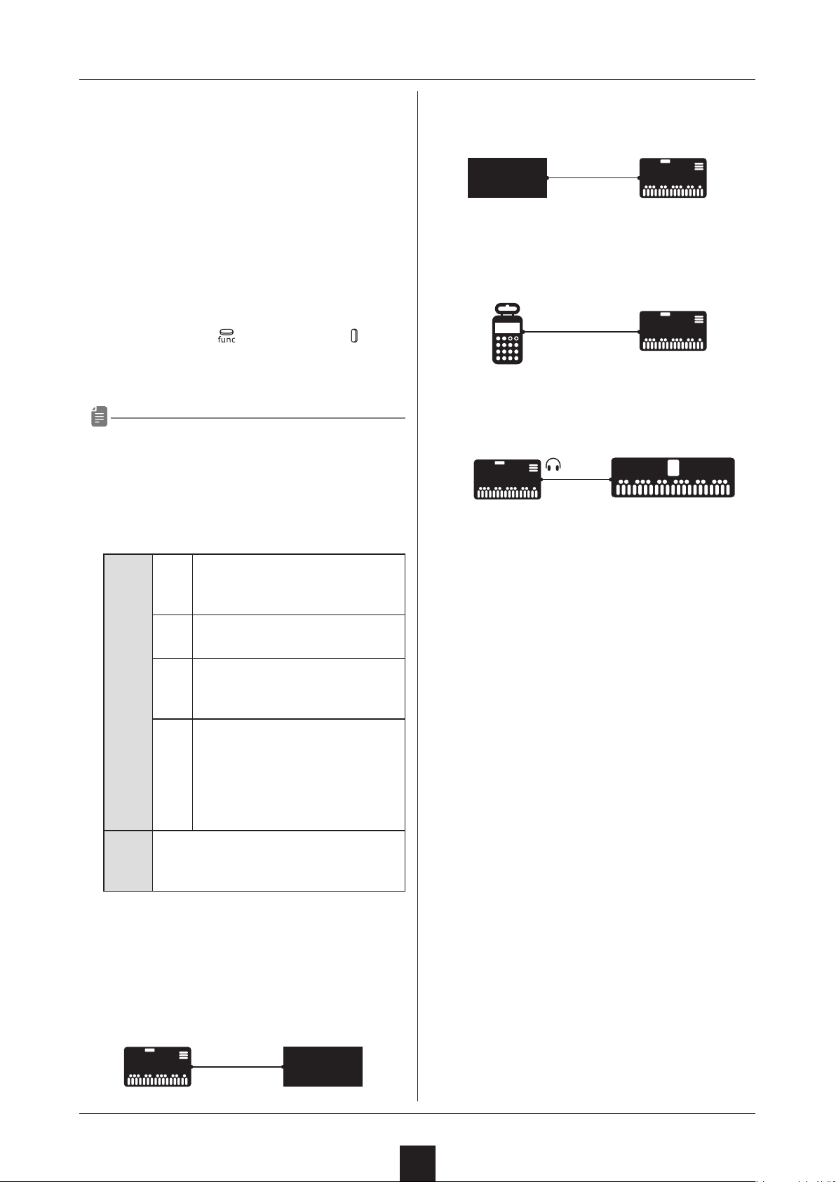
① Connect the LIVEN XFM SYNC IN to the sync output
of the connected device.
② Set the clock source to SYNC. (See “Setting the
clock source” on p.33.)
Synchronizing tempo with an ELZ_1 or
Pocket Operator (PO)
① Connect the LIVEN XFM headphone out to the
ELZ_1 AUX IN or PO input.
② While pressing the
key, and select A.OUT.
③ Turn the VALUE knob to select ON.
• A synchronization signal is output from the left
channel of the headphone output.
• A mono mix signal is output from the right channel
of the headphone output.
•CLOCK MENU
button, press the CLOCK
Example 2 : External device as master synchronizes
with LIVEN XFM
Master Synchronized
External
device
SYNC
OUT
Mono
mini pin cable
SYNC
IN
SRC : SYNC
Example 3 : Pocket Operator as master synchronizes
LIVEN XFM
Master Synchronized
OUT
PUT
Stereo
mini pin cable
LINE
IN
SRC : LN.IN
Example 4 : LIVEN XFM as master synchronizes
with ELZ_1 or Pocket Operator
Master Synchronized
Stereo
mini pin cable
AUX
IN
SRC : INT
A.OUT : ON
MIDI/SYNC synchronization of
INT
external device using LIVEN XFM
clock as master (Example 1)
MIDI synchronization using exter
MIDI
nal device clock as master
SYNC synchronization using exter
SRC
SYNC
nal device clock as master (Exam-
ple 2)
Audio SYNC synchronization using
external device (Pocket Operator)
LN.IN
clock as master (Example 3)
Synchronization signal input on
left channel of LIVEN XFM LINE IN,
mono signal input on right channel
Turn this on when connecting LIVEN XFM
A.OUT
to ELZ_1 or Pocket Operator using Audio
SYNC (Example 4)
Examples of synchronization connections with external
devices
-
-
Example 1 : LIVEN XFM as master synchronizes
external device
Master Synchronized
SYNC
OUT
Mono
mini pin cable
SYNC
IN
External
device
SRC : INT
16
Page 17
Track sequencing
This section explains sequence input and settings for
individual tracks.
Step recording
① Press the button (lights red).
The LED for the current step will blink. The LEDs for
steps that already have notes will light.
② Press the
button for the selected page will light red.)
• The pattern length corresponds to page buttons as
follows.
1 – 16
17 – 32
33 – 48
49 – 64
• Page buttons are enabled or disabled according to
the length of the pattern.
③ Press the step button for the position to input.
The input note sounds (continuously with sustain),
and the step LED blinks.
• The
the step position. (Step notes will sound during
movement).
or button to select the page. (The
button lit green
button lit green
button lit orange
button lit orange
VALUE knob can also be turned to change
keys will overwrite notes on steps. (See “Recording
sound locking automation to steps” on p.18.)
• Notes cannot be tied from the last page to the rst
page.
• During tied note input, if a step in a position earlier
than the current step is pressed, it will be reversed.
• The CLR button can be used even when not
recording.
Copying and pasting steps during
step recording
① Press the button (lights red).
The LED for the current step will blink. The LEDs for
steps that already have notes will light.
② Press the button for the step to be copied.
The LED for the selected step will blink.
③ While pressing the
• COPY will appear on the display.
④ Press the button for the paste destination step.
⑤ While pressing the
key.
• DONE will appear on the display.
• Tie data will not be copied.
button, press the COPY key.
button, press the PASTE
④ Play notes on the keyboard.
The notes of keys pressed sound (continuously with
sustain).
• Playing the same note that has already been input
on the step will clear it.
• By pressing a dierent step button while continuing
to hold a keyboard key, notes can be input on all
the steps in between. (Changing pages is also
possible.) If tie is enabled, a tied note will be input
between the steps. (If the same note already exists
on a step of the tied note, it will be overwritten.)
• While pressing and holding
to delete note and parameter lock data for that
step. (If that step includes a tied note, the entire
tied note will be deleted. It will not be divided.)
• When AUTO STEP is ON, after all keyboard keys are
released, the sequencer will advance to the next
step, and the note on that step will sound.
• When sound locking is activated, playing keyboard
, press a step button
Automatically advancing steps during
step recording (auto step mode)
① While pressing the button, press the AUTO
STEP key, and select ON or OFF.
• ON or OFF will appear on the display.
Recording in real time
① After pressing the button, press the button.
② While the pattern is playing back, play the keyboard
at the desired input times.
• If a pre-count has been set, playback will start after
the pre-count. (The pre-count will be shown on the
display.)
17
Page 18
Track sequencing
• To input tied notes, while pressing the
press the
• When sound locking is activated, playing keyboard
keys will overwrite notes on steps. (See “Recording
sound locking automation to steps” on p.18.)
button to enable the tie function.
button,
Directly inputting notes on steps
① Press
• During pattern playback, press a page button to
lock to that page. Press
② Press and hold the button for the step that you want
to add a note to.
③ Play notes on the keyboard.
• Notes can also be directly input on steps by
pressing step buttons while playing the keyboard.
or to select the page.
to unlock.
Enabling the input of longer notes (tied
notes)
① While pressing the button, press the button
to turn it on (lit red).
simultaneously.
Recording parameter locking automation
in real time
① Select the track on which you want to record
parameter operations.
② While pressing the
button (lights red).
③ Press the
• If a pre-count has been set, playback will start after
the pre-count. (The pre-count will be shown on the
display.)
④ Use the knobs to change parameters.
button to play the pattern.
button, press the
Recording sound locking automation to
steps
① Select the track on which you want to record the
current sound.
② Press
③ Press the
④ Press and hold the button for the step on which you
want to input the current sound.
⑤ Play notes on the keyboard.
or to select the page.
button twice (lights orange).
Recording parameter locking automation
① Select the track on which you want to record
parameter operations.
② Press
• During pattern playback, press a page button to
lock to that page. Press
③ Press and hold the button for the step on which you
want to change a parameter.
④ Use the knobs to change parameters.
• After parameters have been recorded, this data will
not be saved if the pattern is not saved.
• Parameters cannot be recorded in STUTTER mode.
• FX SPEED, FX AMOUNT, ptn level, velo, PTN BPM
and global BPM cannot be parameter locked.
• Multiple step parameters cannot be changed
or to select the page.
to unlock.
• Locking works the same way when step recording.
• During real-time recording, notes input with the
current sound (parameter lock data) are also
recorded. (Only synth engine parameter data is
recorded. Filter, LFO and sweep parameters, as
well as
GATE and → fx data is not recorded.)
• Notes will be overwritten during recording.
, swing, track pan, track level, RELEASE &
Turning parameter locking automation
on/o
① Select the track on which parameter locking will be
turned on/o. (See “Selecting tracks” on p.8.)
② Press the
This lights green when parameter locking is on and
orange when both parameter and sound locking are
on. When neither are on, it is unlit.
When parameter locking is on, recorded parameter
lock data is applied to change parameters.
button.
18
Page 19
Track sequencing
Initializing parameter lock automation
① Select the pattern on which to clear parameter
locks. (See “Selecting patterns” on p.13.)
② Select the track on which to clear parameter locks.
(See “Selecting tracks” on p.8.)
③ Press and hold the
④ Press the
• When parameter lock data initialization has
completed, CLR will appear on the display.
button.
button.
Clearing note and parameter lock
automation data
① While pressing the button, press a step to clear
its note and parameter data.
• While pressing the button, steps that have
parameter lock data blink.
• When recording notes (
will be cleared.
• When recording parameters (
only parameter data will be cleared.
• Normally, when the
red, note and parameter data will be cleared.
button lit red), only notes
button lit red),
and buttons are lit
• Notes can be set to 1/1, 1/2, 1/.4, 1/4, 1/.8,
1/2T, 1/8, 1/.16, 1/4T, 1/16, or 1/32. (“.”
indicates a dotted note, and “T” indicates a triplet
length.)
Setting the track playback unit used
during random playback
① While pressing the
button (lights unless OFF).
② Turn the
unit.
• The playback unit is shown on the display.
• The set playback unit will be used for random
playback.
• The setting options are OFF, 1, 2, 4, 8 and 16.
• Playback will include all steps.
• If set to OFF, the track will not be played randomly
even when the sequence mode is set to RANDOM.
VALUE knob to change the playback
button, press the
Changing the track length
① While pressing the button, press the
button.
② Turn the
• The length is shown on the display.
• The setting range is 1 – 64.
• Pressing the
of 16, 32, 48 and 64 steps.
• Playback will loop using the set number of steps for
each track.
VALUE knob to change the length.
button cycles through lengths
Changing the note length of
a single step
① While pressing the button, press the button.
② Turn the
• The note length is shown on the display.
VALUE knob to change the note length.
19
Page 20
Sound editing
This section explains how to create and edit sounds.
Editing sounds
① While pressing the button, press the EDIT key.,
and use the included sound editing panel overlay.
The step LED for the selected sound will light.
• The name of the current bank is shown on the
display.
• When in sound editing mode, patterns cannot be
played back.
• Play the keyboard to hear the selected sound.
• While pressing the
buttons to change octaves.
② Press the
bank.
• There are 32 banks.
• The bank name appears temporarily on the display.
• The potentiometer
turned to select banks.
button, press the
buttons to select the
VALUE knob can also be
⑦ Use the buttons and
knob to select the save destination.
• The save location can also be selected by pressing
a step button.
• The bank name is shown on the display while an
button is being pressed.
• The sound name is shown on the display while the
VALUE knob is being turned.
• The sound of the save destination can be checked
by playing the keyboard while pressing the
button.
⑧ Press the
⑨ Input the name. (The character at the current
position blinks.)
• Use the buttons to move the
input position left and right. (Three dot positions
occur between the four characters.)
• Turn the
turn the dot on/o at a dot position).
• Uppercase alphabet letters and numbers can be
used.
button.
VALUE knob to select the character (or
VALUE
③ Turn the
• Sounds can also be selected by pressing the step
buttons.
• The sound name appears on the display.
④ Press the
The selected
⑤ Adjust parameters. (For details, see “Editing sound
parameters”.)
• Parameter values are shown on the display.
• “----” appears for buttons that do not affect
parameter adjustment.
• The EDITED LED lights when values differ from
saved values.
VALUE knob to select a sound.
button to enter sound editing mode.
and buttons light.
⑩ Press the
sound editing mode.
button to save the sound and end
Clearing sounds
① Follow steps ① – ④ in “Editing sounds”.
② Press the
• INIT will appear on the display.
• The selected sound will be set to default values.
• The sound can be further edited after this.
button.
Copying sounds
① Follow steps ① – ④ in “Editing sounds”.
② Press the
③ Use the
knob to select the number of the sound to be copied.
button.
buttons and
VALUE
⑥ When done editing parameters, press the
The step LED for the selected sound will light.
button.
20
Page 21
Sound editing
• The save destination can also be selected by
pressing a step button.
• The bank name is shown on the display while an
button is being pressed.
• The sound name is shown on the display while the
VALUE knob is being turned.
• The sound of the copy source can be checked by
playing the keyboard while pressing the
④ Press the
sound editing mode.
button to copy the sound and start
button.
Changing sound names
① Follow steps ① – ④ in “Editing sounds”.
② Press the
③ Input the name.
• Use the buttons to move the
input position left and right. (Three dot positions
occur between the four characters.)
• Turn the
turn the dot on/o at a dot position).
• Uppercase alphabet letters and numbers can be
used.
button.
VALUE knob to select the character (or
Capturing synth engine sounds
(capture mode)
① While pressing the button, press the
key.
• Capture mode can only be enabled when the synth
engines are X-LAB and LIBRARY.
• CPTR will appear on the display.
② Use the
knob to select the save destination.
• The save destination can also be selected by
pressing a step button.
• The bank name is shown on the display while an
button is being pressed.
• The sound name is shown on the display while the
VALUE knob is being turned.
• The sound of the save destination can be checked
by playing the keyboard while pressing the
button.
• While pressing the
buttons to change octaves.
③ Press the
button to return to normal mode.
buttons and
button, press the
CAPTURE
VALUE
④ Press the
return to sound editing mode.
button to save the name change and
Changing sound bank names
① Follow steps ① – ② in “Editing sounds”.
② Press the
③ Input the name.
• Use the buttons to move the
input position left and right. (Three dot positions
occur between the four characters.)
• Turn the
turn the dot on/o at a dot position).
• Uppercase alphabet letters and numbers can be
used.
④ Press the
return to sound selection.
button.
VALUE knob to select the character (or
button to save the name change and
• Press the CLR button to cancel saving.
• The captured sound might be slightly dierent from
the original sound.
21
Page 22
Creating sounds with operators using the editing overlay
This section explains how to edit sound parameters.
Use the included sound editing panel overlay when
editing.
Explanations assume that sound editing mode has
already been enabled
Follow steps ① – ④ in “Editing sounds” to activate sound
editing mode.
• In sound editing mode, the
buttons function as octave buttons.
• The voice mode can be changed by pressing the
play button.
• The page 2 adj knob can be used to adjust the
voice mode (legato speed)
Selecting the operator to edit
① Press the OPERATOR button for the operator to
edit.
The selected OPERATOR button lights red.
• The step buttons enclosed in the orange line
are parameters that can be used to control each
oscillator and the mixer separately.
• In the QUICK EDIT area, regardless of the selected
operator, parameters for each operator can be
changed directly.
• If a step button that cannot be controlled or does
not have parameters is pressed, “----” will appear on
the display.
② Press the button.
③ Press an OP/MIXER RECEIVE LEVEL
The OP/MIXER RECEIVE LEVEL
• The setting value is shown on the display.
④ Turn the
of the operator selected in step ① .
• The level is shown on the display.
• When the connection source and connection
destination are different operators, the setting
range is 0 – 127. When they are the same operator,
the range is -63.0 - +64.0.
• Setting values higher than 63.0 will gradually
increase noise.
• This is the feedback value for connections to
the same operator (for example, setting the OP1
connection level when operator 1 is selected).
• When the feedback is negative, the sound will
change to contain increasingly more odd harmonics.
• Feedback can also be set by turning the
(page 2) of each operator.
• Both the encoder and potentiometer
knobs can be used. (With feedback, the encoder
type knob adjusts in 0.1 increments while the
potentiometer type knob adjusts in 1.0 increments.)
VALUE knob to set the connection level
1 – 4 button.
1 – 4 LED lights.
fb knobs
VALUE
Muting operators
① Press the OPERATOR button for the selected
operator.
The OPERATOR button will light orange (or red when
selected).
• OFF will appear on the display.
• Pressing the OPERATOR button of a muted
operator will select it. Pressing the button again
will stop muting the operator. (ON will appear on the
display.)
• The operators are only muted during sound editing,
and the mute setting is not saved.
Setting connection levels and feedback
between operators
① Press an OPERATOR button to select that operator.
Setting operator ratios
① Press an OPERATOR button to select that operator.
② Press the
③ Press the
The
• The setting value is shown on the display.
④ Turn the
• The ratio is shown on the display with a decimal
point.
• The setting range is 0.5 – 32 in 0.01 steps.
• This can also be set by turning the
FINE knobs of each operator. (The RATIO knob
button.
button.
LED will light.
VALUE knob to set the ratio.
RATIO and
22
Page 23
Creating sounds with operators using the editing overlay
can only change the value to 0.5 or a whole number,
while the
values.)
• Both the encoder and potentiometer
knobs can be used.
FINE knob can change it by decimal
VALUE
Setting operator levels
① Press an OPERATOR button to select that operator.
② Press the
③ Press the
The
• The setting value is shown on the display.
• This can also be set by turning the
(page 2) of each operator.
④ Turn the
button.
button.
LED will light.
VALUE knob to set the level.
level knobs
Setting operators to xed mode
① Press an OPERATOR button to select that operator.
② Press the
③ Press the
The
• The setting value is shown on the display.
④ Turn the
• ON or OFF will appear on the display.
• When ON, the operator will output the set frequency
regardless of input notes.
• Both the encoder and potentiometer
knobs can be used.
button.
button.
LED will light.
VALUE knob to turn this ON/OFF.
VALUE
• The level is shown on the display.
• The setting range is 0 – 127.
• The value can be set from -∞ to +6 dB (63 is 0
dB).
• Both the encoder and potentiometer
knobs can be used.
VALUE
Setting operator detuning
① Press an OPERATOR button to select that operator.
② Press the
③ Press the
The
• The setting value is shown on the display.
④ Turn the
button.
button.
LED will light.
VALUE knob to set the detuning.
Setting the frequency when in xed
mode
① Press an OPERATOR button to select that operator.
② Press the
③ Press the
The
• The setting value is shown on the display.
④ Turn the
• The frequency is shown on the display.
• The setting range is 1.0 – 9831 Hz.
• This can also be set by turning the
and
• Both the encoder and potentiometer
knobs can be used.
button.
button.
LED will light.
VALUE knob to set the frequency.
FINE knobs of each operator.
RATIO/FREQ
VALUE
• The detuning is shown on the display.
• The setting range is - 63 – +63.
• This can also be set by turning the
(page 2) of each operator.
• Both the encoder and potentiometer
knobs can be used.
detune
knobs
VALUE
Setting operator envelopes
① Press an OPERATOR button to select that operator.
② Press the
• Press for LEVEL settings and
23
or button.
for time
Page 24
Creating sounds with operators using the editing overlay
settings.
③ Press an envelope generator button.
The LED for that envelope generator button will light.
• The setting value is shown on the display.
④ Turn the
• The level or time is shown on the display.
• The setting range is 0 – 127.
• Both the encoder and potentiometer
knobs can be used.
• When A LEVEL is set to 0, after playing a key and
the set time elapses, decay will begin.
• Although these are labeled ADSR, the LEVEL values
can be set freely, so envelopes with a variety of
shapes can be set.
VALUE knob to set the envelope value.
VALUE
② Press the button.
③ Press the
The
• The setting value is shown on the display.
④ Turn the
• ON or OFF will appear on the display.
• Both the encoder and potentiometer
knobs can be used.
button.
LED will light.
VALUE knob to turn it on or o.
VALUE
Setting the pitch envelope
① Press the button.
② Press the
• Press PAGE 1 for LEVEL settings and page 2 for
time settings.
or button.
Setting operator envelope curves
① Press an OPERATOR button to select that operator.
② Press the
③ Press the
The
• The setting value is shown on the display.
④ Turn the
• The curve is shown on the display.
• The setting range is - 18 - +18.
• As the number increases in the negative direction,
the envelope curve takes eect faster.
• As the number increases in the positive direction,
the envelope curve takes eect slower.
• At 0 the envelope curve becomes linear.
• Both the encoder and potentiometer
knobs can be used.
button.
or button.
or button LED will light.
VALUE knob to set the curve.
VALUE
③ Press an envelope generator button.
• The setting value is shown on the display.
④ Turn the
• The level or time is shown on the display.
• The LEVEL setting range is - 48 – +48.
• The time setting range is 0 – 127.
• Both the encoder and potentiometer
knobs can be used.
• When A LEVEL is set to 0, after playing a key and
the set time elapses, decay will begin.
• Although these are labeled ADSR, the LEVEL values
can be set freely, so envelopes with a variety of
shapes can be set.
VALUE knob to set the envelope value.
VALUE
Turning the pitch envelope on/o
① Press an OPERATOR button to select that operator.
Setting the operator keyboard gain
scaling depths (left/right)
① Press an OPERATOR button to select that operator.
② Press the
24
button.
Page 25
Creating sounds with operators using the editing overlay
③ Press the
The
• The setting value is shown on the display.
④ Turn the
• The depth is shown on the display.
• The setting range is - 63 – +63.
• Both the encoder and potentiometer
knobs can be used.
or button.
or LED will light.
VALUE knob to set the depth.
VALUE
Setting the operator keyboard gain
scaling curves (left/right)
① Press an OPERATOR button to select that operator.
② Press the
③ Press the
The
• The setting value is shown on the display.
④ Turn the
button.
or button.
or LED will light.
VALUE knob to select the curve.
④ Turn the
• The scaling position is shown on the display.
• Seven scaling positions can be selected: C1, C2,
C3, C4, C5, C6 and C7.
• Both the encoder and potentiometer
knobs can be used.
VALUE knob to set the scaling position.
VALUE
Setting operator velocity sensitivity
① Press an OPERATOR button to select that operator.
② Press the
③ Press the
The
• The setting value is shown on the display.
④ Turn the
sensitivity.
• The sensitivity is shown on the display.
• The higher the value, the more velocity will affect
the operator level.
• The setting range is 0 – 127.
• Both the encoder and potentiometer
knobs can be used.
button.
button.
LED will light.
VALUE knob to set the velocity
VALUE
• The curve is shown on the display.
• Two curve types can be chosen.
1. LINEAR(LINE on display)
2. EXPONENTIAL (EXP on display)
• Both the encoder and potentiometer
knobs can be used.
VALUE
Setting the operator keyboard gain
scaling position
① Press an OPERATOR button to select that operator.
② Press the
③ Press the
The
• The setting value is shown on the display.
button.
button.
LED will light.
Setting the operator keyboard time
scaling
① Press an OPERATOR button to select that operator.
② Press the
③ Press the
The
• The setting value is shown on the display.
④ Turn the
scaling aects time.
• The parameter value is shown on the display.
• The higher the value, the more envelope time is
lengthened for low notes and shortened as notes
become higher.
button.
button.
LED will light.
VALUE knob to set how much keyboard
25
Page 26
Creating sounds with operators using the editing overlay
• The setting range is 0 – 127.
• Both the encoder and potentiometer
knobs can be used.
VALUE
Setting operator to mixer connection
levels
① Press the button.
② Press the
③ Press an OP/MIXER RECEIVE LEVEL
The OP/MIXER RECEIVE LEVEL
• The setting value is shown on the display.
④ Turn the
of the operator to the mixer.
• The level is shown on the display.
• The setting range is 0 – 127.
• This can be adjusted from -∞ to 0 dB.
• This can also be set by turning the
RECEIVE LEVEL
• Both the encoder and potentiometer
knobs can be used.
button.
1 – 4 button.
1 – 4 LED lights.
VALUE knob to set the connection level
1 – 4 knobs.
VALUE
MIXER
① While pressing the button, press the
button.
The
• The setting value is shown on the display.
• The setting range is AL01–AL16.
② Turn the
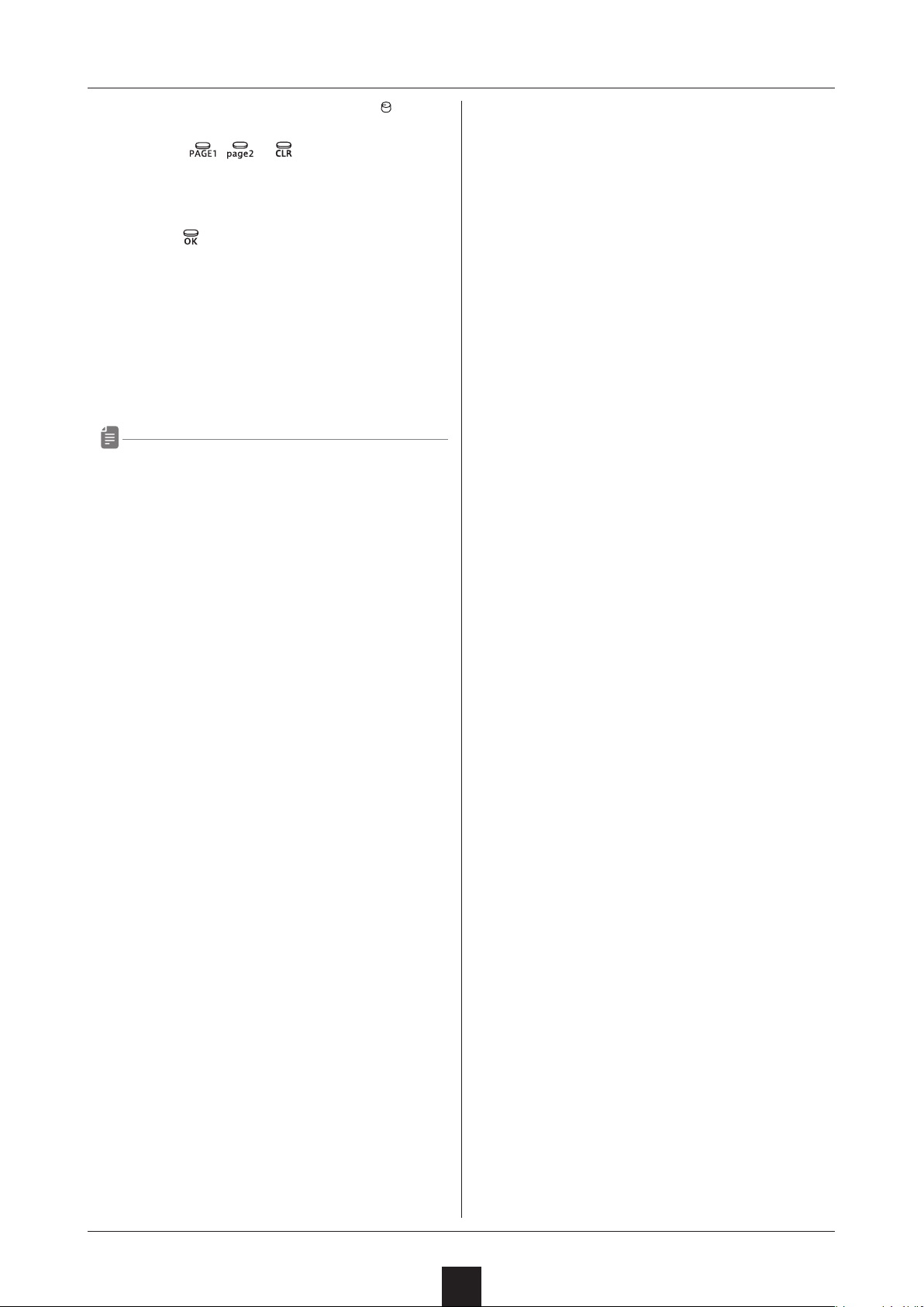
• The algorithm number is shown on the display
• The following 16 algorithm types can be selected.
(
OP4 shown in order from left to right.)
and buttons will light.
VALUE knob to select the algorithm.
is “carrier” and is “modulator” with OP1 to
Setting the mixer output level
① Press the button.
② Press the
③ Press the
The
• The setting value is shown on the display.
④ Turn the
level.
• The level is shown on the display.
• The setting range is - 63 – +63.
• This changes it in a range of - 12 – +12 dB.
button.
button.
LED will light.
VALUE knob to set the MIXER output
Selecting algorithms and setting
operator connections
26
Page 27
Creating sounds with operators using the editing overlay
• Both the encoder and potentiometer
knobs can be used.
• Press the
selection.
, or button to end algorithm
VALUE
③ Press the
algorithm selection.
button to select the algorithm and end
Changing the voice mode and playing
during sound editing
① Press the VOICE MODE button to select the voice
mode.
• The mode is shown on the display.
• 3 voice modes can be chosen.
1. POLY: Up to 6 voices can be output
simultaneously in this mode
2. MONO: In this single voice mode, each note
retriggers the sound.
3. LEGATO (LGT on display): In this single voice
mode, overlapping notes are not retriggered.
• The legato time can be changed using page 2 adj.
27
Page 28
External input settings
This section explains settings related to external input.
Changing the FX send amount
① While pressing the button, press the
button, and set the send amount.
The
OFF.
• The send amount is shown on the display.
• This can also be changed with the
• The setting options are OFF and 1 – 127.
• Pressing the
10, 30, 50, 70, 90, 110 and 127 values.
Changing the gain
① While pressing the button, press the LINE IN
button, and select GAIN.
② Turn the
LED will light for any setting other than
VALUE knob.
button cycles through OFF,
VALUE knob to change the gain.
• The gain is shown on the display.
• The setting range is 0 – 127.
• This can be adjusted from -∞ to +6 dB.
• 90 is 0 dB.
• When using an insert effect that is OFF, it will be
disabled and the sound output directly. Otherwise,
signals are sent to the insert eect at 0 dB and not
output directly.
Setting mono/stereo
① While pressing the button, press the LINE IN
button, and select MONO.
② Turn the
VALUE knob to turn this ON/OFF.
28
Page 29
MIDI settings
This section explains settings related to MIDI.
Setting track MIDI channels
① While pressing the button, press the MIDI CH
key, and select T1.CH - T4.CH.
② Turn the
• The channel is shown on the display.
• The setting range is OFF and CH.01 – CH.16.
• The channel will be used for sending and receiving.
VALUE knob to set the channel.
Setting the MIDI channels for pattern
parameters
① While pressing the button, press the MIDI CH
key, and select PT.CH.
② Turn the
• The channel is shown on the display.
• The setting range is OFF and CH.01 – CH.16.
• The channel will be used for sending and receiving.
VALUE knob to set the channel.
Setting the MIDI channel for accessing
the active track (auto channel)
① While pressing the button, press the MIDI CH
key, and select AT.CH.
② Turn the
VALUE knob to set the channel.
Setting the program change channel
① While pressing the button, press the MIDI CH
key, and select PC.CH.
② Turn the
change channel.
• The channel is shown on the display.
• The setting options are AUTO and CH.01–CH.16.
VALUE knob to change the program
Turning control change transmission
on/o
① While pressing the button, press the MIDI key,
and select TX.CC.
② Turn the
• ON/OFF will appear on the display.
• Control change reception is always enabled.
VALUE knob to turn this ON/OFF.
Turning MIDI clock output on/o
① While pressing the button, press the MIDI key,
and select TX.CK.
② Turn the
• ON/OFF will appear on the display.
VALUE knob to turn this ON/OFF.
• The channel is shown on the display.
• The setting range is OFF and CH.01 – CH.16.
• The channel will be used for sending and receiving.
Setting the output channel
① While pressing the button, press the MIDI CH
key, and select O.CH.
② Turn the
use.
• The channel is shown on the display.
• The setting options are TRCK and AUTO.
VALUE knob to select the channel to
Setting MIDI OUT
① While pressing the
and select M.OUT.
② Turn the
• OUT/THRU will appear on the display.
VALUE knob, and set MIDI OUT.
button, press the MIDI key,
Setting MIDI command receipt and
transmission
① While pressing the button, press the MIDI key,
and select M.CMD.
② Turn the
command setting.
• The setting is shown on the display.
VALUE knob, and select the MIDI
29
Page 30
MIDI settings
• 4 settings can be chosen.
1. OFF: Neither transmit nor receive
2. RX: Only receive
3. TX: Only transmit
4. RX.TX: Transmit and receive
Turning active sensing transmission
on/o
① While pressing the button, press the MIDI key,
and select TX.AS.
② Turn the
• ON/OFF will appear on the display.
VALUE knob to turn this ON/OFF.
Turning active sensing reception
on/o
① While pressing the button, press the MIDI key,
and select RX.AS.
② Turn the
VALUE knob to turn this ON/OFF.
• ON/OFF will appear on the display.
• When a program change message is received, it
switches to the pattern of the received number.
• ON/OFF will appear on the display.
Turning program change transmission
on/o
① While pressing the button, press the MIDI key,
and select TX.PC.
② Turn the
• ON/OFF will appear on the display.
• When a new pattern is selected, and the sequencer
is stopped, a MIDI program change message will
be sent instantly which corresponds with the new
pattern number.
• When a new pattern is selected, and the sequencer
is playing, a MIDI program change message will be
sent after the current pattern ends and the new
pattern starts.
VALUE knob to turn this ON/OFF.
Turning program change reception on/o
① While pressing the button, press the MIDI key,
and select RX.PC.
② Turn the
VALUE knob to turn this ON/OFF.
30
Page 31
Saving and loading user data
This section explains ways to save and load user data.
User data can be saved and loaded via MIDI. Connect a
device that can transmit and receive data by MIDI to the
LIVEN XFM.
Exporting pattern data
① Select the pattern you want to export. (See
“Selecting patterns” on p.13.)
② While pressing the
key, and select P.EXP.
③ Turn the
④ Press the
• Regardless of data transmission status, the
button can be pressed to cancel.
• After transmission completes, DONE will appear on
the display and normal mode will resume.
VALUE knob to select PTN.
button to start transmission.
button, press the DATA
Exporting sound data
① Enter sound editing mode and select the sound you
want to export. (See “Editing sounds”steps ① – ④
on p.20.)
② Press the
button to start transmission.
• After reception completes, the received pattern
data will be applied to the current pattern. (It will
not be saved.)
• Save the received pattern data if necessary.
Importing sound data
① Enter sound editing mode and select the import
destination sound. (See “Editing sounds” steps ① ④ on p.20.)
② Start transmitting data from the transmitting device.
• After reception completes, the received sound data
will be applied to the current sound (It will not be
saved.)
• Save the received sound data if necessary.
Importing sound banks
① Enter sound editing mode and select the import
destination bank. (See “Editing sounds” steps ① – ②
on p.20.)
② Start transmitting data from the transmitting device.
• Regardless of data transmission status, the
button can be pressed to cancel.
• After transmission completes, DONE will appear on
the display and sound editing mode will resume.
Exporting sound banks
① Enter sound editing mode and select the bank you
want to export. (See “Editing sounds” steps ① – ②
on p.20.)
② Press the
• Regardless of data transmission status, the
button can be pressed to cancel.
• After transmission completes, DONE will appear on
the display and bank selection status will resume.
button to start transmission.
Importing pattern data
① Put the unit into normal mode, and start transmitting
data from the transmitting device.
• After receiving completes, SAVE will appear on the
display.
③ Press the
• After saving completes, DONE will appear on the
display.
button.
Backing up user data
① While pressing the 4 button, press the POWER
switch to turn on the LIVEN XFM.
② Turn the
③ Press the
• The step button LEDs show the progress of data
transmission. (They will light in order from step
button LED 1. Transmission is complete when all
step LEDs 1–16 have lit.)
• Regardless of data transmission status, the
VALUE knob to select EXPT.
button to start transfer.
31
Page 32
Saving and loading user data
button can be pressed to cancel.
• After transmission completes, DONE will appear on
the display, and the unit will start up normally.
• The size of the backup data is 2,657,568 bytes.
• If the size of the data is dierent, the backup might
have failed. If this occurs, before step ③ , turn the
VALUE knob while pressing the
increase the transmission interval. (The default
value is 0.)
Restoring user data
① While pressing the button, press the POWER
switch to turn on the LIVEN XFM.
② Turn the
③ Press the
from the other device.
• The step button LEDs show the progress of data
transmission. (They will light in order from step
button LED 1. Transmission is complete when all
step LEDs 1–16 have lit.)
• Regardless of the data reception status, the
Crouton can be pressed to cancel. (Received data
will be discarded.)
VALUE knob to select IMPT.
button, and start data transmission
button to
④ After receiving completes, SAVE will appear on the
display. Press the
data to restore the unit.
• After restoration completes, DONE will appear on
the display, and the unit will start up normally.
button to use the received
32
Page 33
System settings
This section explains settings related to the system.
Setting the automatic power o function
① Press and hold the button.
② Press the
③ Turn the
power o setting.
• Automatic power o has four settings.
1. OFF: Automatic power o is disabled.
2. 30 minutes (0.5 on display): Power will turn off
automatically after 30 minutes without operation.
3. 1 hour (1H on display): Power will turn off
automatically after 1 hour without operation.
4. 3 hours (3H on display): Power will turn off
automatically after 3 hours without operation.
5. 6 hours (6H on display): Power will turn off
automatically after 6 hours without operation.
• Unsaved data will be cleared when the power turns
o automatically. Always save data that is needed.
SYSTEM key, and select A.PWR.
VALUE knob to select the automatic
Setting the battery type
① Press and hold the button.
② Press the
③ Turn the
battery.
SYSTEM key, and select BATT.
VALUE knob to select the type of
Setting the clock source
① Press and hold the button.
② Press the
③ Turn the
• The clock source is shown on the display.
• Four types of clock sources can be selected.
1. INTERNAL (INT on display): Use LIVEN XFM
internal clock
2. MIDI: Use clock from MIDI
3. SYNC: Use clock from SYNC IN
4. LINE IN (LN.IN on display): Use clock from LINE IN
CLOCK key, and select SRC.
VALUE knob to set the clock source.
Setting SYNC IN polarity
① Press and hold the button.
② Press the
③ Turn the
• The polarity is shown on the display.
• Two types of polarity can be selected.
1. FALL: Synchronizes with the falling of the sync
signal.
2. RISE: Synchronizes with the rising of the sync
signal.
CLOCK key, and select S.I.PO.
VALUE knob to set the polarity.
• Three types of batteries can be selected.
1. Alkaline (ALKL on display)
2. Nickel-metal hydride (NIMH on display)
3. Lithium (LTHM on display)
• The remaining charge shown could be higher
than the actual amount depending on the type of
rechargeable battery.
• Please set this correctly because it effects
operation time.
Setting the master tuning
① Press and hold the button.
② Press the
③ Turn the
• The master tuning setting (in cents) will appear on
the display.
• The setting range is -75 – +75.
SYSTEM key, and select TUNE.
VALUE knob to set the master tuning.
Setting SYNC OUT polarity
① Press and hold the button.
② Press the
③ Turn the
• The polarity is shown on the display.
• Two types of polarity can be selected.
1. FALL: Synchronizes with the falling of the sync
signal.
2. RISE: Synchronizes with the rising of the sync
signal.
CLOCK key, and select S.O.PO.
VALUE knob to set the polarity.
Setting knob movement behavior
① Press and hold the
② Press the latch button to turn knob latching on/o.
• Two types of knob movement behavior can be
button.
33
Page 34
System settings
selected.
1. Jump (
the parameter changes immediately.
2. Latch (
affect the parameter value until its position
reaches that value. Then, the value follows the
knob.
• When in latch mode, the movement of the dots
on the display show the direction of the current
parameter value. (If the parameter value is lower
than the knob setting, they light to appear to be
flowing left. If the value is higher, they appear to
be owing right. The farther away the value is, the
faster they ow.)
button unlit): When a knob is moved,
button lit red): The knob does not
Enabling/disabling speaker output
① Press and hold the button.
② Press the
key and select MUTE or SPK.
Setting the headphone gain
① Press and hold the button.
② Press the
key, and select the gain.
preset version (P M.m on display).
• Press the same page button again to show the
build number.
• Press the
button to start up normally.
Restoring to factory default settings
(factory reset)
① While pressing the 3 button, press and hold
the POWER switch.
• The LIVEN XFM will start up, and F.RST will appear
on the display.
② Press the
• After resetting completes, DONE will appear on the
display.
• Press the
button.
button to cancel.
• The headphone gain is shown on the display.
• Three volume settings can be selected.
1. LOUD
2. NORM
3. SOFT
• Set this correctly to prevent damage to the
headphones or external device being used.
Checking the system version
① While pressing the 2 button, press and hold
the POWER switch.
• The LIVEN XFM will start up, and VER. will appear
on the display.
② Press the
button to show the system version.
Updating the rmware
① While pressing the button, press and hold the
POWER switch.
• The LIVEN XFM will start up, and UPDT will appear
on the display.
② Transmit the rmware from the sending device (Sys.
Ex).
• The step LEDs will light to show the progress.
(100% when step LED 16 is reached.)
• RCV will appear on the display.
• When receiving completes, the
green and the
button will light red.
button will light
• The system version (S M.m) is shown on the display
(M: major version, m: minor version).
• Press the
M.m on display). Press the
button to check the boot version (B
button to check the
③ After transmission completes, press the
to execute the update.
• Press the button to cancel the update and start
up normally.
34
button
Page 35

System settings
• The step LEDs will light to show the progress.
(100% when step LED 16 is reached.)
• If the update occurred properly, DONE will appear. (If
a problem occurred, an error code will appear.)
④ Restart the unit.
35
Page 36
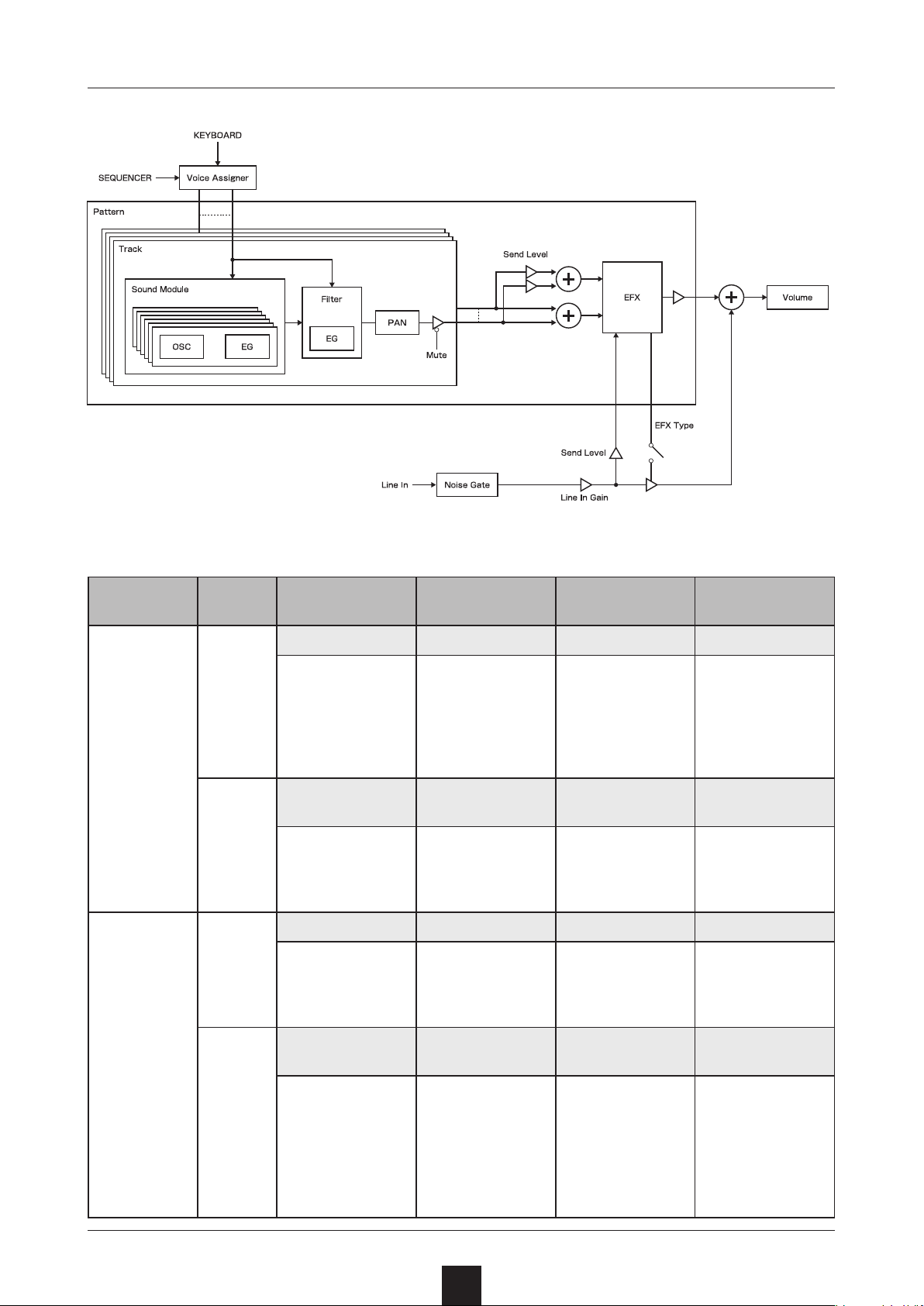
Appendix
Figure 1. Sound architecture
Table 1. Synthesizer engine parameter list
Synth engine
X-LAB
shift
button
OFF
ON
OFF
Main Knob 1 Main Knob 2 Main Knob 3 Main Knob 4
Sound 1 Sound 2 Combination Combination color
Sounds 1 to 16 of
the selected bank
(The default value
is 1)
Bank 1 Bank 2
1~32
(The default value
is 1)
Sound 1 Sound 2 Switching time Delay
Sounds 1 to 16 of
the selected bank
(The default value
is 1)
Sounds 1 to 16 of
the selected bank
(The default value
(The default value
Sounds 1 to 16 of
the selected bank
(The default value
is 2)
1~32
is 1)
is 2)
<63 ~ <01、01>
~ 63>
(The default value
is <01)
Pitch lock &
envelope lock
--.--、--.EG、PT.--、
PT.EG
(The default value
is PT.--)
0 ~ 127
(The default value
is 10)
RED、ORNG、
YLLW、GRRN、
BLUE、LI.BL、
PRPL
(The default value
is RED)
Tone
0 ~ 127
(The default value
is 127)
0 ~ 127
(The default value
is 63)
XFORM
ON
Bank 1 Bank 2
1~32
(The default value
is 1)
1~32
(The default value
is 2)
36
Pitch lock &
envelope lock
--.--、--.EG、PT.--、
PT.EG
(The default value
is PT.--)
Switching color
RED、ORNG、
YLLW、GRRN、
BLUE、LI.BL、
PRPL、WHT、
BLCK
(The default value
is RED)
Page 37
Appendix
Synth engine
X-LFO
shift
button
OFF
ON
Main Knob 1 Main Knob 2 Main Knob 3 Main Knob 4
Sound 1 Sound 2 LFO rate LFO shape
SINE(sine wave)、
SAQR(square
wave)、TRI
(triangle wave)、
SAW(sawtooth
Sounds 1 to 16 of
the selected bank
(The default value
is 1)
Bank 1 Bank 2
1~32
(The default value
is 1)
Sounds 1 to 16 of
the selected bank
(The default value
is 2)
1~32
(The default value
is 1)
0 ~ 127(The
default value is
63)
Pitch lock &
envelope lock
--.--、--.EG、PT.--、
PT.EG
(The default value
is PT.--)
wave)、R.SAW
(reverse sawtooth
wave)、RAND
(random wave)、
LOG(logarithmic
wave)、R.LOG
(reverse
logarithmic wave)
(The default value
is SINE)
Morphing color
RED、ORNG、
YLLW、GRRN、
BLUE、LI.BL、
PRPL、WHT、
BLCK
(The default value
is RED)
Bank Sound Attack time Tone
OFF
LIBRARY
ON
1~32
(The default value
is 1)
― ― ― ―
― ― ― ―
(The default value
X-LAB
• 1 ↔ 2: This adjusts the balance of SOUND 1 and
SOUND 2 in the combined sound.
• COLOR: This adjusts the balance of the operators
in the combined sound.
• lock: This turns pitch and envelope locking on and
o.
• tone: This adjusts high-frequency elements.
XFORM
• TIME: This adjusts the time switching from SOUND
1 to SOUND 2
• DELAY: This adjusts the time before switching from
SOUND 1 to SOUND 2.
• lock: This turns pitch and envelope locking on and
o.
• color: This adjusts the balance of the operators at
the time they change.
1~16
is 1)
-63 ~ ORG ~ +63
(The default value
is ORG)
0 ~ 127
(The default value
is 127)
X-LFO
• RATE: This adjusts the morphing frequency of
SOUND 1 and SOUND 2.
• SHAPE: This adjusts the morphing shape.
• lock: This turns pitch and envelope locking on and
o.
• color: This adjusts the balance of the operators at
the time they change.
LIBRARY
• ATTACK: This adjusts the attack time of each
operator.
• TONE: This adjusts high-frequency elements.
37
 Loading...