

Page 1

COMPREHENSIVE INTERNET SECURIT Y
SSSS So n i c WALL Security Ap p l i a n c es
SonicOS Enhanced 2.5
™
Administrator's Guide
Page 2

PART 1: Introduction to SonicOS Enhanced 2.5
Chapter 1: Introduction . . . . . . . . . . . . . . . . . . . . . . . . . . . . . . . . . . . . . . . . . . . . . . . . . . . . . . . .1
SonicOS Enhanced 2.5 . . . . . . . . . . . . . . . . . . . . . . . . . . . . . . . . . . . . . . . . . . . . . . . . . . . . 1
What’s New in SonicOS Enhanced 2.5. . . . . . . . . . . . . . . . . . . . . . . . . . . . . . . . . . . . . . . 1
About this Guide. . . . . . . . . . . . . . . . . . . . . . . . . . . . . . . . . . . . . . . . . . . . . . . . . . . . . . . . . . 2
Organization of this Guide . . . . . . . . . . . . . . . . . . . . . . . . . . . . . . . . . . . . . . . . . . . . . . . . 3
Guide Conventions . . . . . . . . . . . . . . . . . . . . . . . . . . . . . . . . . . . . . . . . . . . . . . . . . . . . . . 5
SonicWALL Technical Support. . . . . . . . . . . . . . . . . . . . . . . . . . . . . . . . . . . . . . . . . . . . . . . 6
SonicWALL Support Solutions . . . . . . . . . . . . . . . . . . . . . . . . . . . . . . . . . . . . . . . . . . . . . 6
More Information on SonicWALL Products . . . . . . . . . . . . . . . . . . . . . . . . . . . . . . . . . . . . . 7
Chapter 2: Getting Started. . . . . . . . . . . . . . . . . . . . . . . . . . . . . . . . . . . . . . . . . . . . . . . . . . . . . 9
Configuring Your Management Station . . . . . . . . . . . . . . . . . . . . . . . . . . . . . . . . . . . . . . . 9
Accessing the Management Interface. . . . . . . . . . . . . . . . . . . . . . . . . . . . . . . . . . . . . . . 10
Troubleshooting . . . . . . . . . . . . . . . . . . . . . . . . . . . . . . . . . . . . . . . . . . . . . . . . . . . . . . . 11
Using the Management Interface . . . . . . . . . . . . . . . . . . . . . . . . . . . . . . . . . . . . . . . . . . 12
PART 2: System
Chapter 3: Viewing Status Information . . . . . . . . . . . . . . . . . . . . . . . . . . . . . . . . . . . . . . 17
System > Status . . . . . . . . . . . . . . . . . . . . . . . . . . . . . . . . . . . . . . . . . . . . . . . . . . . . . . . . . 17
Wizards . . . . . . . . . . . . . . . . . . . . . . . . . . . . . . . . . . . . . . . . . . . . . . . . . . . . . . . . . . . . . . 18
System Messages. . . . . . . . . . . . . . . . . . . . . . . . . . . . . . . . . . . . . . . . . . . . . . . . . . . . . . 18
System Information . . . . . . . . . . . . . . . . . . . . . . . . . . . . . . . . . . . . . . . . . . . . . . . . . . . . . 18
Latest Alerts . . . . . . . . . . . . . . . . . . . . . . . . . . . . . . . . . . . . . . . . . . . . . . . . . . . . . . . . . . 18
Registration and Security Services . . . . . . . . . . . . . . . . . . . . . . . . . . . . . . . . . . . . . . . . . 19
Network Interfaces . . . . . . . . . . . . . . . . . . . . . . . . . . . . . . . . . . . . . . . . . . . . . . . . . . . . . 22
Chapter 4: Managing SonicWALL Security Services Licenses. . . . . . . . . . . . . . 23
System > Licenses . . . . . . . . . . . . . . . . . . . . . . . . . . . . . . . . . . . . . . . . . . . . . . . . . . . . . . . 23
Security Services Summary . . . . . . . . . . . . . . . . . . . . . . . . . . . . . . . . . . . . . . . . . . . . . . 23
Manage Security Services Online . . . . . . . . . . . . . . . . . . . . . . . . . . . . . . . . . . . . . . . . . . 24
Manual Upgrade . . . . . . . . . . . . . . . . . . . . . . . . . . . . . . . . . . . . . . . . . . . . . . . . . . . . . . . 25
Manual Upgrade for Closed Environments . . . . . . . . . . . . . . . . . . . . . . . . . . . . . . . . . . . 25
Chapter 5: Configuring SonicWALL Security Appliance Administration Settings27
System > Administration . . . . . . . . . . . . . . . . . . . . . . . . . . . . . . . . . . . . . . . . . . . . . . . . . . 27
Firewall Name . . . . . . . . . . . . . . . . . . . . . . . . . . . . . . . . . . . . . . . . . . . . . . . . . . . . . . . . . 27
Administrator Name & Password . . . . . . . . . . . . . . . . . . . . . . . . . . . . . . . . . . . . . . . . . . 28
Login Security . . . . . . . . . . . . . . . . . . . . . . . . . . . . . . . . . . . . . . . . . . . . . . . . . . . . . . . . . 28
Web Management Settings. . . . . . . . . . . . . . . . . . . . . . . . . . . . . . . . . . . . . . . . . . . . . . . 28
Advanced Management . . . . . . . . . . . . . . . . . . . . . . . . . . . . . . . . . . . . . . . . . . . . . . . . . 29
Enabling SNMP Management. . . . . . . . . . . . . . . . . . . . . . . . . . . . . . . . . . . . . . . . . . . . . 30
Enable GMS Management . . . . . . . . . . . . . . . . . . . . . . . . . . . . . . . . . . . . . . . . . . . . . . . 31
VPN Client Download URL . . . . . . . . . . . . . . . . . . . . . . . . . . . . . . . . . . . . . . . . . . . . . . . 33
Chapter 6: Configuring Time Settings . . . . . . . . . . . . . . . . . . . . . . . . . . . . . . . . . . . . . . . 35
System > Time . . . . . . . . . . . . . . . . . . . . . . . . . . . . . . . . . . . . . . . . . . . . . . . . . . . . . . . . . . 35
System Time . . . . . . . . . . . . . . . . . . . . . . . . . . . . . . . . . . . . . . . . . . . . . . . . . . . . . . . . . . 36
NTP Settings. . . . . . . . . . . . . . . . . . . . . . . . . . . . . . . . . . . . . . . . . . . . . . . . . . . . . . . . . . 36
SONICWALL SONICOS ENHANCED 2.5 ADMINISTRATOR’S GUIDE
i
Page 3

:
Chapter 7: Managing SonicWALL Security Appliance Firmware. . . . . . . . . . . . .37
System > Settings . . . . . . . . . . . . . . . . . . . . . . . . . . . . . . . . . . . . . . . . . . . . . . . . . . . . . . . .37
Settings . . . . . . . . . . . . . . . . . . . . . . . . . . . . . . . . . . . . . . . . . . . . . . . . . . . . . . . . . . . . . . 37
Firmware Management . . . . . . . . . . . . . . . . . . . . . . . . . . . . . . . . . . . . . . . . . . . . . . . . . . 38
SafeMode - Rebooting the SonicWALL Security Appliance. . . . . . . . . . . . . . . . . . . . . . . 40
FIPS (PRO 3060/PRO 4060/PRO 5060) . . . . . . . . . . . . . . . . . . . . . . . . . . . . . . . . . . . . . 41
Chapter 8: Using Diagnostic Tools & Restarting the SonicWALL Security Appliance
43
System > Diagnostics . . . . . . . . . . . . . . . . . . . . . . . . . . . . . . . . . . . . . . . . . . . . . . . . . . . . . 43
Diagnostic Tools. . . . . . . . . . . . . . . . . . . . . . . . . . . . . . . . . . . . . . . . . . . . . . . . . . . . . . . . 44
System > Restart . . . . . . . . . . . . . . . . . . . . . . . . . . . . . . . . . . . . . . . . . . . . . . . . . . . . . . . . .48
PART 3: Network
Chapter 9: Configuring Interfaces . . . . . . . . . . . . . . . . . . . . . . . . . . . . . . . . . . . . . . . . . . . .51
Network > Interfaces . . . . . . . . . . . . . . . . . . . . . . . . . . . . . . . . . . . . . . . . . . . . . . . . . . . . . . 51
Setup Wizard . . . . . . . . . . . . . . . . . . . . . . . . . . . . . . . . . . . . . . . . . . . . . . . . . . . . . . . . . .51
Physical Interfaces . . . . . . . . . . . . . . . . . . . . . . . . . . . . . . . . . . . . . . . . . . . . . . . . . . . . . . 51
SonicOS Enhanced Secure Objects . . . . . . . . . . . . . . . . . . . . . . . . . . . . . . . . . . . . . . . . 52
Transparent Mode . . . . . . . . . . . . . . . . . . . . . . . . . . . . . . . . . . . . . . . . . . . . . . . . . . . . . . 52
Interface Settings . . . . . . . . . . . . . . . . . . . . . . . . . . . . . . . . . . . . . . . . . . . . . . . . . . . . . . . 52
Inteface Traffic Statistics . . . . . . . . . . . . . . . . . . . . . . . . . . . . . . . . . . . . . . . . . . . . . . . . . 53
Configuring the LAN/DMZ/Custom Interface (Static) . . . . . . . . . . . . . . . . . . . . . . . . . . . 53
Configuring the LAN/DMZ/Custom Interface
(Transparent Mode) . . . . . . . . . . . . . . . . . . . . . . . . . . . . . . . . . . . . . . . . . . . . . . . . . . . 55
Configuring the WLAN Interface. . . . . . . . . . . . . . . . . . . . . . . . . . . . . . . . . . . . . . . . . . . . 57
Configuring the WAN Interface. . . . . . . . . . . . . . . . . . . . . . . . . . . . . . . . . . . . . . . . . . . . . 57
Configuring the Advanced Settings for the WAN Interface . . . . . . . . . . . . . . . . . . . . . . . 60
Chapter 10:Setting Up WAN Failover and Load Balancing . . . . . . . . . . . . . . . . . . .63
Network > WAN Failover & LB . . . . . . . . . . . . . . . . . . . . . . . . . . . . . . . . . . . . . . . . . . . . . . 63
WAN Failover Caveats . . . . . . . . . . . . . . . . . . . . . . . . . . . . . . . . . . . . . . . . . . . . . . . . . . . 63
Setting Up WAN Failover and Load Balancing. . . . . . . . . . . . . . . . . . . . . . . . . . . . . . . . . 64
WAN Load Balancing Statistics . . . . . . . . . . . . . . . . . . . . . . . . . . . . . . . . . . . . . . . . . . . . 68
Chapter 11:Configuring Zones . . . . . . . . . . . . . . . . . . . . . . . . . . . . . . . . . . . . . . . . . . . . . . . .69
Network > Zones . . . . . . . . . . . . . . . . . . . . . . . . . . . . . . . . . . . . . . . . . . . . . . . . . . . . . . . . .69
How Zones Work . . . . . . . . . . . . . . . . . . . . . . . . . . . . . . . . . . . . . . . . . . . . . . . . . . . . . . . 69
Predefined Zones . . . . . . . . . . . . . . . . . . . . . . . . . . . . . . . . . . . . . . . . . . . . . . . . . . . . . . . 70
Security Types . . . . . . . . . . . . . . . . . . . . . . . . . . . . . . . . . . . . . . . . . . . . . . . . . . . . . . . . .71
Allow Interface Trust. . . . . . . . . . . . . . . . . . . . . . . . . . . . . . . . . . . . . . . . . . . . . . . . . . . . . 71
Enabling SonicWALL Security Services on Zones. . . . . . . . . . . . . . . . . . . . . . . . . . . . . . 71
The Zone Settings Table . . . . . . . . . . . . . . . . . . . . . . . . . . . . . . . . . . . . . . . . . . . . . . . . . 72
Adding a New Zone . . . . . . . . . . . . . . . . . . . . . . . . . . . . . . . . . . . . . . . . . . . . . . . . . . . . . 73
Deleting a Zone . . . . . . . . . . . . . . . . . . . . . . . . . . . . . . . . . . . . . . . . . . . . . . . . . . . . . . . . 73
Configuring the WLAN Zone . . . . . . . . . . . . . . . . . . . . . . . . . . . . . . . . . . . . . . . . . . . . . . 73
Chapter 12:Configuring DNS Settings . . . . . . . . . . . . . . . . . . . . . . . . . . . . . . . . . . . . . . . .77
Network > DNS . . . . . . . . . . . . . . . . . . . . . . . . . . . . . . . . . . . . . . . . . . . . . . . . . . . . . . . . . .77
ii
SONICWALL SONICOS ENHANCED 2.5 ADMINISTRATOR’S GUIDE
Page 4

Chapter 13:Configuring Address Objects . . . . . . . . . . . . . . . . . . . . . . . . . . . . . . . . . . . . 79
Network > Address Objects . . . . . . . . . . . . . . . . . . . . . . . . . . . . . . . . . . . . . . . . . . . . . . . . 79
Types of Address Objects . . . . . . . . . . . . . . . . . . . . . . . . . . . . . . . . . . . . . . . . . . . . . . . . 79
Address Object Groups. . . . . . . . . . . . . . . . . . . . . . . . . . . . . . . . . . . . . . . . . . . . . . . . . . 80
Creating and Managing Address Objects . . . . . . . . . . . . . . . . . . . . . . . . . . . . . . . . . . . . 80
Default Address Objects and Groups . . . . . . . . . . . . . . . . . . . . . . . . . . . . . . . . . . . . . . . 81
SonicWALL PRO 5060 . . . . . . . . . . . . . . . . . . . . . . . . . . . . . . . . . . . . . . . . . . . . . . . . . . 81
SonicWALL PRO 4060 . . . . . . . . . . . . . . . . . . . . . . . . . . . . . . . . . . . . . . . . . . . . . . . . . . 82
SonicWALL PRO 3060 . . . . . . . . . . . . . . . . . . . . . . . . . . . . . . . . . . . . . . . . . . . . . . . . . . 83
SonicWALL PRO 2040 . . . . . . . . . . . . . . . . . . . . . . . . . . . . . . . . . . . . . . . . . . . . . . . . . . 84
Adding an Address Object . . . . . . . . . . . . . . . . . . . . . . . . . . . . . . . . . . . . . . . . . . . . . . . 85
Creating Group Address Objects . . . . . . . . . . . . . . . . . . . . . . . . . . . . . . . . . . . . . . . . . . 85
Public Server Wizard . . . . . . . . . . . . . . . . . . . . . . . . . . . . . . . . . . . . . . . . . . . . . . . . . . . 86
Chapter 14:Configuring Routes . . . . . . . . . . . . . . . . . . . . . . . . . . . . . . . . . . . . . . . . . . . . . . 87
Network > Routing . . . . . . . . . . . . . . . . . . . . . . . . . . . . . . . . . . . . . . . . . . . . . . . . . . . . . . . 87
Route Advertisement . . . . . . . . . . . . . . . . . . . . . . . . . . . . . . . . . . . . . . . . . . . . . . . . . . . 87
Route Policies . . . . . . . . . . . . . . . . . . . . . . . . . . . . . . . . . . . . . . . . . . . . . . . . . . . . . . . . . . 89
Policy Based Routing . . . . . . . . . . . . . . . . . . . . . . . . . . . . . . . . . . . . . . . . . . . . . . . . . . . 89
Route Policies Table . . . . . . . . . . . . . . . . . . . . . . . . . . . . . . . . . . . . . . . . . . . . . . . . . . . . 90
A Route Policy Example . . . . . . . . . . . . . . . . . . . . . . . . . . . . . . . . . . . . . . . . . . . . . . . . . 90
Chapter 15:Configuring NAT Policies . . . . . . . . . . . . . . . . . . . . . . . . . . . . . . . . . . . . . . . . 93
Network > NAT Policies . . . . . . . . . . . . . . . . . . . . . . . . . . . . . . . . . . . . . . . . . . . . . . . . . . . 93
NAT Policies Table . . . . . . . . . . . . . . . . . . . . . . . . . . . . . . . . . . . . . . . . . . . . . . . . . . . . . 94
NAT Policy Settings Explained . . . . . . . . . . . . . . . . . . . . . . . . . . . . . . . . . . . . . . . . . . . . 95
NAT Policies Q&A . . . . . . . . . . . . . . . . . . . . . . . . . . . . . . . . . . . . . . . . . . . . . . . . . . . . . . 96
Creating NAT Policies. . . . . . . . . . . . . . . . . . . . . . . . . . . . . . . . . . . . . . . . . . . . . . . . . . . 97
Chapter 16:Managing ARP Traffic . . . . . . . . . . . . . . . . . . . . . . . . . . . . . . . . . . . . . . . . . . 105
Network > ARP. . . . . . . . . . . . . . . . . . . . . . . . . . . . . . . . . . . . . . . . . . . . . . . . . . . . . . . . . 105
Navigating and Sorting the ARP Cache Table Entries . . . . . . . . . . . . . . . . . . . . . . . . . 105
Flushing the ARP Cache. . . . . . . . . . . . . . . . . . . . . . . . . . . . . . . . . . . . . . . . . . . . . . . . 106
Chapter 17:Setting Up the DHCP Server . . . . . . . . . . . . . . . . . . . . . . . . . . . . . . . . . . . 107
Network > DHCP Server . . . . . . . . . . . . . . . . . . . . . . . . . . . . . . . . . . . . . . . . . . . . . . . . . 107
Enabling DHCP Server . . . . . . . . . . . . . . . . . . . . . . . . . . . . . . . . . . . . . . . . . . . . . . . . . 107
Configuring DHCP Server for Dynamic Ranges . . . . . . . . . . . . . . . . . . . . . . . . . . . . . . 108
Configuring Static DHCP Entries . . . . . . . . . . . . . . . . . . . . . . . . . . . . . . . . . . . . . . . . . 110
Current DHCP Leases . . . . . . . . . . . . . . . . . . . . . . . . . . . . . . . . . . . . . . . . . . . . . . . . . 111
Chapter 18:Using IP Helper . . . . . . . . . . . . . . . . . . . . . . . . . . . . . . . . . . . . . . . . . . . . . . . . . 113
Network > IP Helper . . . . . . . . . . . . . . . . . . . . . . . . . . . . . . . . . . . . . . . . . . . . . . . . . . . . . 113
IP Helper Settings . . . . . . . . . . . . . . . . . . . . . . . . . . . . . . . . . . . . . . . . . . . . . . . . . . . . . 113
IP Helper Policies . . . . . . . . . . . . . . . . . . . . . . . . . . . . . . . . . . . . . . . . . . . . . . . . . . . . . 114
Adding an IP Helper Policy . . . . . . . . . . . . . . . . . . . . . . . . . . . . . . . . . . . . . . . . . . . . . . 114
Editing an IP Helper Policy . . . . . . . . . . . . . . . . . . . . . . . . . . . . . . . . . . . . . . . . . . . . . . 114
Deleting IP Helper Policies . . . . . . . . . . . . . . . . . . . . . . . . . . . . . . . . . . . . . . . . . . . . . . 114
Chapter 19:Setting Up Web Proxy Forwarding . . . . . . . . . . . . . . . . . . . . . . . . . . . . . 115
Network > Web Proxy . . . . . . . . . . . . . . . . . . . . . . . . . . . . . . . . . . . . . . . . . . . . . . . . . . . 115
Configuring Automatic Proxy Forwarding (Web Only) . . . . . . . . . . . . . . . . . . . . . . . . . 115
Bypass Proxy Servers Upon Proxy Failure . . . . . . . . . . . . . . . . . . . . . . . . . . . . . . . . . . 116
SONICWALL SONICOS ENHANCED 2.5 ADMINISTRATOR’S GUIDE
iii
Page 5

:
PART 4: Wireless
Chapter 20:Managing SonicPoints. . . . . . . . . . . . . . . . . . . . . . . . . . . . . . . . . . . . . . . . . . 119
Wireless > SonicPoints . . . . . . . . . . . . . . . . . . . . . . . . . . . . . . . . . . . . . . . . . . . . . . . . . . . 119
Before Managing SonicPoints . . . . . . . . . . . . . . . . . . . . . . . . . . . . . . . . . . . . . . . . . . . . . . 119
SonicPoint Provisioning Profiles . . . . . . . . . . . . . . . . . . . . . . . . . . . . . . . . . . . . . . . . . . . . 120
Configuring a SonicPoint Profile. . . . . . . . . . . . . . . . . . . . . . . . . . . . . . . . . . . . . . . . . . . 120
Updating SonicPoint Settings. . . . . . . . . . . . . . . . . . . . . . . . . . . . . . . . . . . . . . . . . . . . . 123
Updating SonicPoint Firmware. . . . . . . . . . . . . . . . . . . . . . . . . . . . . . . . . . . . . . . . . . . . 124
Automatic Provisioning (SDP & SSPP) . . . . . . . . . . . . . . . . . . . . . . . . . . . . . . . . . . . . . 124
SonicPoint States . . . . . . . . . . . . . . . . . . . . . . . . . . . . . . . . . . . . . . . . . . . . . . . . . . . . . . 125
Chapter 21:Viewing Station Status . . . . . . . . . . . . . . . . . . . . . . . . . . . . . . . . . . . . . . . . . . 127
Wireless > Station Status . . . . . . . . . . . . . . . . . . . . . . . . . . . . . . . . . . . . . . . . . . . . . . . . . 127
Event and Statistics Reporting . . . . . . . . . . . . . . . . . . . . . . . . . . . . . . . . . . . . . . . . . . . . 127
Chapter 22:Using and Configuring IDS . . . . . . . . . . . . . . . . . . . . . . . . . . . . . . . . . . . . . 129
Wireless > IDS. . . . . . . . . . . . . . . . . . . . . . . . . . . . . . . . . . . . . . . . . . . . . . . . . . . . . . . . . .129
Detecting Wireless Access Points . . . . . . . . . . . . . . . . . . . . . . . . . . . . . . . . . . . . . . . . . 129
Wireless Intrusion Detection Services . . . . . . . . . . . . . . . . . . . . . . . . . . . . . . . . . . . . . . 129
PART 5: Firewall
Chapter 23:Configuring Access Rules . . . . . . . . . . . . . . . . . . . . . . . . . . . . . . . . . . . . . . 133
Firewall > Access Rules . . . . . . . . . . . . . . . . . . . . . . . . . . . . . . . . . . . . . . . . . . . . . . . . . . 133
Stateful Packet Inspection Default Access Rules Overview. . . . . . . . . . . . . . . . . . . . . . 134
Using Bandwidth Management with Access Rules Overview . . . . . . . . . . . . . . . . . . . . 134
Configuration Task List . . . . . . . . . . . . . . . . . . . . . . . . . . . . . . . . . . . . . . . . . . . . . . . . . . . 135
Displaying Access Rules with View Styles . . . . . . . . . . . . . . . . . . . . . . . . . . . . . . . . . . . 135
Configuring Access Rules for a Zone. . . . . . . . . . . . . . . . . . . . . . . . . . . . . . . . . . . . . . . 136
Adding Access Rules . . . . . . . . . . . . . . . . . . . . . . . . . . . . . . . . . . . . . . . . . . . . . . . . . . . 137
Editing an Access Rule . . . . . . . . . . . . . . . . . . . . . . . . . . . . . . . . . . . . . . . . . . . . . . . . . 138
Deleting an Access Rule . . . . . . . . . . . . . . . . . . . . . . . . . . . . . . . . . . . . . . . . . . . . . . . . 138
Enabling and Disabling an Access Rule. . . . . . . . . . . . . . . . . . . . . . . . . . . . . . . . . . . . . 139
Displaying Access Rule Traffic Statistics . . . . . . . . . . . . . . . . . . . . . . . . . . . . . . . . . . . . 139
Access Rule Configuration Examples . . . . . . . . . . . . . . . . . . . . . . . . . . . . . . . . . . . . . . . . 139
Enabling Ping . . . . . . . . . . . . . . . . . . . . . . . . . . . . . . . . . . . . . . . . . . . . . . . . . . . . . . . . . 139
Blocking LAN Access for Specific Services . . . . . . . . . . . . . . . . . . . . . . . . . . . . . . . . . . 140
Enabling Bandwidth Management on an Access Rule. . . . . . . . . . . . . . . . . . . . . . . . . . 140
Chapter 24:Configuring Advanced
Access Rule Settings141
Firewall > Advanced . . . . . . . . . . . . . . . . . . . . . . . . . . . . . . . . . . . . . . . . . . . . . . . . . . . . . 141
Detection Prevention . . . . . . . . . . . . . . . . . . . . . . . . . . . . . . . . . . . . . . . . . . . . . . . . . . . 142
Dynamic Ports . . . . . . . . . . . . . . . . . . . . . . . . . . . . . . . . . . . . . . . . . . . . . . . . . . . . . . . . 142
Source Routed Packets . . . . . . . . . . . . . . . . . . . . . . . . . . . . . . . . . . . . . . . . . . . . . . . . . 142
TCP Connection Inactivity Timeout . . . . . . . . . . . . . . . . . . . . . . . . . . . . . . . . . . . . . . . . 142
Access Rule Service Options . . . . . . . . . . . . . . . . . . . . . . . . . . . . . . . . . . . . . . . . . . . . . 142
Chapter 25:Setting Access Rule Schedules . . . . . . . . . . . . . . . . . . . . . . . . . . . . . . . . 143
Firewall > Schedules . . . . . . . . . . . . . . . . . . . . . . . . . . . . . . . . . . . . . . . . . . . . . . . . . . . . . 143
Schedules. . . . . . . . . . . . . . . . . . . . . . . . . . . . . . . . . . . . . . . . . . . . . . . . . . . . . . . . . . . .143
Adding a Schedule . . . . . . . . . . . . . . . . . . . . . . . . . . . . . . . . . . . . . . . . . . . . . . . . . . . . . 144
Deleting Schedules . . . . . . . . . . . . . . . . . . . . . . . . . . . . . . . . . . . . . . . . . . . . . . . . . . . . 144
iv
SONICWALL SONICOS ENHANCED 2.5 ADMINISTRATOR’S GUIDE
Page 6

Chapter 26:Configuring Firewall Services. . . . . . . . . . . . . . . . . . . . . . . . . . . . . . . . . . . 145
Firewall > Services . . . . . . . . . . . . . . . . . . . . . . . . . . . . . . . . . . . . . . . . . . . . . . . . . . . . . . 145
Default Services Overview . . . . . . . . . . . . . . . . . . . . . . . . . . . . . . . . . . . . . . . . . . . . . . . . 146
Custom Services Configuration Task List . . . . . . . . . . . . . . . . . . . . . . . . . . . . . . . . . . . . 146
Supported Protocols . . . . . . . . . . . . . . . . . . . . . . . . . . . . . . . . . . . . . . . . . . . . . . . . . . . 146
Adding Custom Services. . . . . . . . . . . . . . . . . . . . . . . . . . . . . . . . . . . . . . . . . . . . . . . . 147
Adding a Custom Services Group. . . . . . . . . . . . . . . . . . . . . . . . . . . . . . . . . . . . . . . . . 148
Chapter 27:Configuring Multicast Settings . . . . . . . . . . . . . . . . . . . . . . . . . . . . . . . . . . 151
Firewall > Multicast. . . . . . . . . . . . . . . . . . . . . . . . . . . . . . . . . . . . . . . . . . . . . . . . . . . . . . 151
Multicast Snooping . . . . . . . . . . . . . . . . . . . . . . . . . . . . . . . . . . . . . . . . . . . . . . . . . . . . 152
Multicast Policies . . . . . . . . . . . . . . . . . . . . . . . . . . . . . . . . . . . . . . . . . . . . . . . . . . . . . 152
IGMP State Table . . . . . . . . . . . . . . . . . . . . . . . . . . . . . . . . . . . . . . . . . . . . . . . . . . . . . 152
Configuration Example . . . . . . . . . . . . . . . . . . . . . . . . . . . . . . . . . . . . . . . . . . . . . . . . . 153
Chapter 28:Configuring VoIP Support. . . . . . . . . . . . . . . . . . . . . . . . . . . . . . . . . . . . . . . 155
Firewall > VoIP . . . . . . . . . . . . . . . . . . . . . . . . . . . . . . . . . . . . . . . . . . . . . . . . . . . . . . . . . 155
VoIP Protocols . . . . . . . . . . . . . . . . . . . . . . . . . . . . . . . . . . . . . . . . . . . . . . . . . . . . . . . 155
Configuring the VoIP Settings . . . . . . . . . . . . . . . . . . . . . . . . . . . . . . . . . . . . . . . . . . . . 156
PART 6: VPN
Chapter 29:Configuring VPN Policies . . . . . . . . . . . . . . . . . . . . . . . . . . . . . . . . . . . . . . . 161
VPN > Settings. . . . . . . . . . . . . . . . . . . . . . . . . . . . . . . . . . . . . . . . . . . . . . . . . . . . . . . . . 161
VPN Policy Wizard . . . . . . . . . . . . . . . . . . . . . . . . . . . . . . . . . . . . . . . . . . . . . . . . . . . . 162
VPN Global Settings . . . . . . . . . . . . . . . . . . . . . . . . . . . . . . . . . . . . . . . . . . . . . . . . . . . 163
VPN Policies . . . . . . . . . . . . . . . . . . . . . . . . . . . . . . . . . . . . . . . . . . . . . . . . . . . . . . . . . 163
Currently Active VPN Tunnels . . . . . . . . . . . . . . . . . . . . . . . . . . . . . . . . . . . . . . . . . . . 164
Configuring GroupVPN Policies . . . . . . . . . . . . . . . . . . . . . . . . . . . . . . . . . . . . . . . . . . . . 164
Configuring GroupVPN with IKE using Preshared Secret on the WAN Zone. . . . . . . . 165
Configuring GroupVPN with IKE using 3rd Party Certificates. . . . . . . . . . . . . . . . . . . . 168
Exporting a VPN Client Policy. . . . . . . . . . . . . . . . . . . . . . . . . . . . . . . . . . . . . . . . . . . . 170
Site-to-Site VPN Configurations . . . . . . . . . . . . . . . . . . . . . . . . . . . . . . . . . . . . . . . . . . . . 171
VPN Planning Sheet for Site-to-Site VPN Policies . . . . . . . . . . . . . . . . . . . . . . . . . . . . 171
Creating Site-to-Site VPN Policies . . . . . . . . . . . . . . . . . . . . . . . . . . . . . . . . . . . . . . . . . . 172
Configuring a VPN Policy with IKE using Preshared Secret . . . . . . . . . . . . . . . . . . . . . 174
Configuring a VPN Policy using Manual Key . . . . . . . . . . . . . . . . . . . . . . . . . . . . . . . . 177
Configuring a VPN Policy with IKE using a Third Party Certificate . . . . . . . . . . . . . . . . 181
Chapter 30:Configuring Advanced VPN Settings . . . . . . . . . . . . . . . . . . . . . . . . . . . 185
VPN>Advanced . . . . . . . . . . . . . . . . . . . . . . . . . . . . . . . . . . . . . . . . . . . . . . . . . . . . . . . . 185
Advanced VPN Settings . . . . . . . . . . . . . . . . . . . . . . . . . . . . . . . . . . . . . . . . . . . . . . . . 185
Chapter 31:Configuring DHCP Over VPN . . . . . . . . . . . . . . . . . . . . . . . . . . . . . . . . . . 187
VPN > DHCP over VPN . . . . . . . . . . . . . . . . . . . . . . . . . . . . . . . . . . . . . . . . . . . . . . . . . . 187
DHCP Relay Mode . . . . . . . . . . . . . . . . . . . . . . . . . . . . . . . . . . . . . . . . . . . . . . . . . . . . 187
Configuring the Central Gateway for DHCP Over VPN . . . . . . . . . . . . . . . . . . . . . . . . 187
Configuring DHCP over VPN Remote Gateway . . . . . . . . . . . . . . . . . . . . . . . . . . . . . . 189
Current DHCP over VPN Leases . . . . . . . . . . . . . . . . . . . . . . . . . . . . . . . . . . . . . . . . . 191
Chapter 32:Configuring L2TP Server . . . . . . . . . . . . . . . . . . . . . . . . . . . . . . . . . . . . . . . 193
VPN > L2TP Server . . . . . . . . . . . . . . . . . . . . . . . . . . . . . . . . . . . . . . . . . . . . . . . . . . . . . 193
Configuring the L2TP Server . . . . . . . . . . . . . . . . . . . . . . . . . . . . . . . . . . . . . . . . . . . . 194
SONICWALL SONICOS ENHANCED 2.5 ADMINISTRATOR’S GUIDE
v
Page 7

:
Chapter 33:Configuring VPN Certificates . . . . . . . . . . . . . . . . . . . . . . . . . . . . . . . . . . . 197
VPN>CA Certificates . . . . . . . . . . . . . . . . . . . . . . . . . . . . . . . . . . . . . . . . . . . . . . . . . . . . . 197
Implementing Certificates for VPN Policies . . . . . . . . . . . . . . . . . . . . . . . . . . . . . . . . . . 198
Importing CA Certificates into the SonicWALL Security Appliance . . . . . . . . . . . . . . . . 198
Certificate Details . . . . . . . . . . . . . . . . . . . . . . . . . . . . . . . . . . . . . . . . . . . . . . . . . . . . . . 199
Delete This Certificate . . . . . . . . . . . . . . . . . . . . . . . . . . . . . . . . . . . . . . . . . . . . . . . . . . 199
Certificate Revocation List (CRL) . . . . . . . . . . . . . . . . . . . . . . . . . . . . . . . . . . . . . . . . . . 199
VPN > Local Certificates . . . . . . . . . . . . . . . . . . . . . . . . . . . . . . . . . . . . . . . . . . . . . . . . . . 200
Importing Certificate with Private Key . . . . . . . . . . . . . . . . . . . . . . . . . . . . . . . . . . . . . . 200
Certificate Details . . . . . . . . . . . . . . . . . . . . . . . . . . . . . . . . . . . . . . . . . . . . . . . . . . . . . . 201
Delete This Certificate . . . . . . . . . . . . . . . . . . . . . . . . . . . . . . . . . . . . . . . . . . . . . . . . . . 201
Generating a Certificate Signing Request . . . . . . . . . . . . . . . . . . . . . . . . . . . . . . . . . . . 201
PART 7: Users
Chapter 34:Managing User Status and Authentication Settings . . . . . . . . . . . . 205
Users>Status . . . . . . . . . . . . . . . . . . . . . . . . . . . . . . . . . . . . . . . . . . . . . . . . . . . . . . . . . . .205
User>Settings . . . . . . . . . . . . . . . . . . . . . . . . . . . . . . . . . . . . . . . . . . . . . . . . . . . . . . . . . .206
Authentication Method . . . . . . . . . . . . . . . . . . . . . . . . . . . . . . . . . . . . . . . . . . . . . . . . . . 206
Configuring RADIUS Authentication. . . . . . . . . . . . . . . . . . . . . . . . . . . . . . . . . . . . . . . . 206
Global User Settings . . . . . . . . . . . . . . . . . . . . . . . . . . . . . . . . . . . . . . . . . . . . . . . . . . . 210
Acceptable Use Policy . . . . . . . . . . . . . . . . . . . . . . . . . . . . . . . . . . . . . . . . . . . . . . . . . . 211
Chapter 35:Managing Local Users and
Local Groups213
User > Local Users . . . . . . . . . . . . . . . . . . . . . . . . . . . . . . . . . . . . . . . . . . . . . . . . . . . . . . 213
Viewing Local Users. . . . . . . . . . . . . . . . . . . . . . . . . . . . . . . . . . . . . . . . . . . . . . . . . . . . 214
Adding Local Users . . . . . . . . . . . . . . . . . . . . . . . . . . . . . . . . . . . . . . . . . . . . . . . . . . . . 214
Editing Local Users . . . . . . . . . . . . . . . . . . . . . . . . . . . . . . . . . . . . . . . . . . . . . . . . . . . . 215
Users>Local Groups . . . . . . . . . . . . . . . . . . . . . . . . . . . . . . . . . . . . . . . . . . . . . . . . . . . . . 215
Creating a Local Group . . . . . . . . . . . . . . . . . . . . . . . . . . . . . . . . . . . . . . . . . . . . . . . . . 216
Chapter 36:Managing Guest Services and Guest Accounts . . . . . . . . . . . . . . . . 217
Users > Guest Services. . . . . . . . . . . . . . . . . . . . . . . . . . . . . . . . . . . . . . . . . . . . . . . . . . . 217
Global Guest Settings . . . . . . . . . . . . . . . . . . . . . . . . . . . . . . . . . . . . . . . . . . . . . . . . . . 218
Guest Profiles. . . . . . . . . . . . . . . . . . . . . . . . . . . . . . . . . . . . . . . . . . . . . . . . . . . . . . . . . 218
Users > Guest Accounts . . . . . . . . . . . . . . . . . . . . . . . . . . . . . . . . . . . . . . . . . . . . . . . . . . 219
Adding Guest Accounts . . . . . . . . . . . . . . . . . . . . . . . . . . . . . . . . . . . . . . . . . . . . . . . . . 219
Enabling Guest Accounts . . . . . . . . . . . . . . . . . . . . . . . . . . . . . . . . . . . . . . . . . . . . . . . . 221
Enabling Auto-prune for Guest Accounts . . . . . . . . . . . . . . . . . . . . . . . . . . . . . . . . . . . . 222
Printing Account Details. . . . . . . . . . . . . . . . . . . . . . . . . . . . . . . . . . . . . . . . . . . . . . . . . 222
Users > Guest Status . . . . . . . . . . . . . . . . . . . . . . . . . . . . . . . . . . . . . . . . . . . . . . . . . . . . 223
Logging Accounts off the Appliance . . . . . . . . . . . . . . . . . . . . . . . . . . . . . . . . . . . . . . . . 223
PART 8: Hardware Failover
Chapter 37:Setting Up Hardware Failover . . . . . . . . . . . . . . . . . . . . . . . . . . . . . . . . . . 227
Hardware Failover > Settings . . . . . . . . . . . . . . . . . . . . . . . . . . . . . . . . . . . . . . . . . . . . . . 227
How Hardware Failover Works. . . . . . . . . . . . . . . . . . . . . . . . . . . . . . . . . . . . . . . . . . . . 227
Before Configuring Hardware Failover . . . . . . . . . . . . . . . . . . . . . . . . . . . . . . . . . . . . . . 228
Configuring Hardware Failover. . . . . . . . . . . . . . . . . . . . . . . . . . . . . . . . . . . . . . . . . . . . 231
Sychronizing Firmware. . . . . . . . . . . . . . . . . . . . . . . . . . . . . . . . . . . . . . . . . . . . . . . . . . 233
Monitoring Links . . . . . . . . . . . . . . . . . . . . . . . . . . . . . . . . . . . . . . . . . . . . . . . . . . . . . . . 233
Hardware Failover Status. . . . . . . . . . . . . . . . . . . . . . . . . . . . . . . . . . . . . . . . . . . . . . . . 233
vi
SONICWALL SONICOS ENHANCED 2.5 ADMINISTRATOR’S GUIDE
Page 8

PART 9: Security Services
Chapter 38:Managing Security Services . . . . . . . . . . . . . . . . . . . . . . . . . . . . . . . . . . . . 237
Security Services>Summary . . . . . . . . . . . . . . . . . . . . . . . . . . . . . . . . . . . . . . . . . . . . . . 237
mySonicWALL.com. . . . . . . . . . . . . . . . . . . . . . . . . . . . . . . . . . . . . . . . . . . . . . . . . . . . 237
Security Services Summary . . . . . . . . . . . . . . . . . . . . . . . . . . . . . . . . . . . . . . . . . . . . . 238
Chapter 39:Configuring SonicWALL Content Filter . . . . . . . . . . . . . . . . . . . . . . . . . 241
Security Services>Content Filter . . . . . . . . . . . . . . . . . . . . . . . . . . . . . . . . . . . . . . . . . . . 241
SonicWALL Content Filtering Service . . . . . . . . . . . . . . . . . . . . . . . . . . . . . . . . . . . . . . 241
Content Filter Status . . . . . . . . . . . . . . . . . . . . . . . . . . . . . . . . . . . . . . . . . . . . . . . . . . . 242
Content Filter Type . . . . . . . . . . . . . . . . . . . . . . . . . . . . . . . . . . . . . . . . . . . . . . . . . . . . 243
Restrict Web Features . . . . . . . . . . . . . . . . . . . . . . . . . . . . . . . . . . . . . . . . . . . . . . . . . 244
Trusted Domains. . . . . . . . . . . . . . . . . . . . . . . . . . . . . . . . . . . . . . . . . . . . . . . . . . . . . . 244
Message to Display when Blocking . . . . . . . . . . . . . . . . . . . . . . . . . . . . . . . . . . . . . . . 245
Configuring SonicWALL Filter Properties . . . . . . . . . . . . . . . . . . . . . . . . . . . . . . . . . . . 245
Custom List . . . . . . . . . . . . . . . . . . . . . . . . . . . . . . . . . . . . . . . . . . . . . . . . . . . . . . . . . . 245
Consent. . . . . . . . . . . . . . . . . . . . . . . . . . . . . . . . . . . . . . . . . . . . . . . . . . . . . . . . . . . . . 246
Mandatory Filtered IP Addresses . . . . . . . . . . . . . . . . . . . . . . . . . . . . . . . . . . . . . . . . . 247
Chapter 40:Activating SonicWALL Network Anti-Virus. . . . . . . . . . . . . . . . . . . . . . 249
Security Services>Anti-Virus . . . . . . . . . . . . . . . . . . . . . . . . . . . . . . . . . . . . . . . . . . . . . . 249
Activating SonicWALL Network Anti-Virus . . . . . . . . . . . . . . . . . . . . . . . . . . . . . . . . . . 250
Activating a SonicWALL Network Anti-Virus FREE TRIAL . . . . . . . . . . . . . . . . . . . . . . 250
Security Services>E-Mail Filter . . . . . . . . . . . . . . . . . . . . . . . . . . . . . . . . . . . . . . . . . . . . 251
Chapter 41:Activating Intrusion Prevention Service. . . . . . . . . . . . . . . . . . . . . . . . . 253
Security Services > Intrusion Prevention . . . . . . . . . . . . . . . . . . . . . . . . . . . . . . . . . . . . . 253
SonicWALL IPS Features . . . . . . . . . . . . . . . . . . . . . . . . . . . . . . . . . . . . . . . . . . . . . . . 253
SonicWALL Deep Packet Inspection . . . . . . . . . . . . . . . . . . . . . . . . . . . . . . . . . . . . . . 254
How SonicWALL’s Deep Packet Inspection Works . . . . . . . . . . . . . . . . . . . . . . . . . . . 255
SonicWALL IPS Terminology . . . . . . . . . . . . . . . . . . . . . . . . . . . . . . . . . . . . . . . . . . . . 255
SonicWALL IPS Activation . . . . . . . . . . . . . . . . . . . . . . . . . . . . . . . . . . . . . . . . . . . . . . 256
Activating SonicWALL IPS . . . . . . . . . . . . . . . . . . . . . . . . . . . . . . . . . . . . . . . . . . . . . . 257
Activating the SonicWALL IPS FREE TRIAL . . . . . . . . . . . . . . . . . . . . . . . . . . . . . . . . 257
PART 10: Log
Chapter 42:Managing Log Events. . . . . . . . . . . . . . . . . . . . . . . . . . . . . . . . . . . . . . . . . . . 261
Log > View . . . . . . . . . . . . . . . . . . . . . . . . . . . . . . . . . . . . . . . . . . . . . . . . . . . . . . . . . . . . 261
Log View Table . . . . . . . . . . . . . . . . . . . . . . . . . . . . . . . . . . . . . . . . . . . . . . . . . . . . . . . 262
Refresh . . . . . . . . . . . . . . . . . . . . . . . . . . . . . . . . . . . . . . . . . . . . . . . . . . . . . . . . . . . . . 262
Clear Log . . . . . . . . . . . . . . . . . . . . . . . . . . . . . . . . . . . . . . . . . . . . . . . . . . . . . . . . . . . 262
Export Log. . . . . . . . . . . . . . . . . . . . . . . . . . . . . . . . . . . . . . . . . . . . . . . . . . . . . . . . . . . 263
E-mail Log. . . . . . . . . . . . . . . . . . . . . . . . . . . . . . . . . . . . . . . . . . . . . . . . . . . . . . . . . . . 263
Log Event Messages . . . . . . . . . . . . . . . . . . . . . . . . . . . . . . . . . . . . . . . . . . . . . . . . . . . . 263
Chapter 43:Configuring Log Categories . . . . . . . . . . . . . . . . . . . . . . . . . . . . . . . . . . . . 291
Log > Categories . . . . . . . . . . . . . . . . . . . . . . . . . . . . . . . . . . . . . . . . . . . . . . . . . . . . . . . 291
Log Priority . . . . . . . . . . . . . . . . . . . . . . . . . . . . . . . . . . . . . . . . . . . . . . . . . . . . . . . . . . 292
Log Categories . . . . . . . . . . . . . . . . . . . . . . . . . . . . . . . . . . . . . . . . . . . . . . . . . . . . . . . 292
SONICWALL SONICOS ENHANCED 2.5 ADMINISTRATOR’S GUIDE
vii
Page 9

:
Chapter 44:Configuring Syslog Settings . . . . . . . . . . . . . . . . . . . . . . . . . . . . . . . . . . . . 295
Log > Syslog . . . . . . . . . . . . . . . . . . . . . . . . . . . . . . . . . . . . . . . . . . . . . . . . . . . . . . . . . . . 295
Syslog Settings. . . . . . . . . . . . . . . . . . . . . . . . . . . . . . . . . . . . . . . . . . . . . . . . . . . . . . . . 296
Syslog Servers . . . . . . . . . . . . . . . . . . . . . . . . . . . . . . . . . . . . . . . . . . . . . . . . . . . . . . . . 296
Chapter 45:Configuring Log Automation . . . . . . . . . . . . . . . . . . . . . . . . . . . . . . . . . . . . 297
Log > Automation . . . . . . . . . . . . . . . . . . . . . . . . . . . . . . . . . . . . . . . . . . . . . . . . . . . . . . . 297
E-mail Log Automation . . . . . . . . . . . . . . . . . . . . . . . . . . . . . . . . . . . . . . . . . . . . . . . . . . 297
Mail Server Settings . . . . . . . . . . . . . . . . . . . . . . . . . . . . . . . . . . . . . . . . . . . . . . . . . . . . 298
Chapter 46:Generating Log Reports . . . . . . . . . . . . . . . . . . . . . . . . . . . . . . . . . . . . . . . . 299
Log > Reports . . . . . . . . . . . . . . . . . . . . . . . . . . . . . . . . . . . . . . . . . . . . . . . . . . . . . . . . . .299
Data Collection . . . . . . . . . . . . . . . . . . . . . . . . . . . . . . . . . . . . . . . . . . . . . . . . . . . . . . . . 300
View Data . . . . . . . . . . . . . . . . . . . . . . . . . . . . . . . . . . . . . . . . . . . . . . . . . . . . . . . . . . . .300
Chapter 47:Activating and Enabling SonicWALL ViewPoint . . . . . . . . . . . . . . . . 301
Log > ViewPoint . . . . . . . . . . . . . . . . . . . . . . . . . . . . . . . . . . . . . . . . . . . . . . . . . . . . . . . . 301
Activating ViewPoint. . . . . . . . . . . . . . . . . . . . . . . . . . . . . . . . . . . . . . . . . . . . . . . . . . . . 302
Enabling ViewPoint Settings . . . . . . . . . . . . . . . . . . . . . . . . . . . . . . . . . . . . . . . . . . . . . 303
PART 11: Wizards
Chapter 48:Configuring Internet Connectivity Using the Setup Wizard . . . . . 307
Internet Connectivity Using the Setup Wizard . . . . . . . . . . . . . . . . . . . . . . . . . . . . . . . . . . 307
Configuring a Static IP Address with NAT Enabled . . . . . . . . . . . . . . . . . . . . . . . . . . . . 307
Configuring DHCP Networking Mode. . . . . . . . . . . . . . . . . . . . . . . . . . . . . . . . . . . . . . . 312
Configuring NAT Enabled with PPPoE. . . . . . . . . . . . . . . . . . . . . . . . . . . . . . . . . . . . . . 317
Configuring PPTP Network Mode . . . . . . . . . . . . . . . . . . . . . . . . . . . . . . . . . . . . . . . . . 322
Chapter 49:Configuring a Public Server with the Wizard . . . . . . . . . . . . . . . . . . . 329
Create a Server with the Public Server Wizard . . . . . . . . . . . . . . . . . . . . . . . . . . . . . . . 329
Chapter 50:Configuring VPN Policies with the VPN Policy Wizard . . . . . . . . . 335
Configuring GroupVPN using the VPN Policy Wizard . . . . . . . . . . . . . . . . . . . . . . . . . . . . 335
Using the VPN Policy Wizard . . . . . . . . . . . . . . . . . . . . . . . . . . . . . . . . . . . . . . . . . . . . . 335
Connecting the Global VPN Clients . . . . . . . . . . . . . . . . . . . . . . . . . . . . . . . . . . . . . . . . 338
Configuring a Site-to-Site VPN using the VPN Wizard . . . . . . . . . . . . . . . . . . . . . . . . . . . 339
Using the VPN Wizard to Configure Preshared Secret . . . . . . . . . . . . . . . . . . . . . . . . . 339
Chapter 51:Index. . . . . . . . . . . . . . . . . . . . . . . . . . . . . . . . . . . . . . . . . . . . . . . . . . . . . . . . . . . . 343
viii
SONICWALL SONICOS ENHANCED 2.5 ADMINISTRATOR’S GUIDE
Page 10

Copyright Notice
©
2004 SonicWALL, Inc. All rights reserved.
Under the copyright laws, this manual or the software described within, can not be copied, in whole or
part, without the written consent of the manufacturer, except in the normal use of the software to
make a backup copy. The same proprietary and copyright notices must be affixed to any permitted
copies as were affixed to the original. This exception does not allow copies to be made for others,
whether or not sold, but all of the material purchased (with all backup copies) can be sold, given, or
loaned to another person. Under the law, copying includes translating into another language or
format.
Preface
Chapter :
Chapter :
SonicWALL is a registered trademark of SonicWALL, Inc.
Other product and company names mentioned herein can be trademarks and/or registered
trademarks of their respective companies.
Specifications and descriptions subject to change without notice.
Limited Warranty
SonicWALL, Inc. warrants that commencing from the delivery date to Customer (but in any case
commencing not more than ninety (90) days after the original shipment by SonicWALL), and
continuing for a period of twelve (12) months, that the product will be free from defects in materials
and workmanship under normal use. This Limited Warranty is not transferable and applies only to the
original end user of the product. SonicWALL and its suppliers' entire liability and Customer's sole and
exclusive remedy under this limited warranty will be shipment of a replacement product. At
SonicWALL's discretion the replacement product may be of equal or greater functionality and may be
of either new or like-new quality. SonicWALL's obligations under this warranty are contingent upon
the return of the defective product according to the terms of SonicWALL's then-current Support
Services policies.
This warranty does not apply if the product has been subjected to abnormal electrical stress,
damaged by accident, abuse, misuse or misapplication, or has been modified without the written
permission of SonicWALL.
DISCLAIMER OF WARRANTY. EXCEPT AS SPECIFIED IN THIS WARRANTY, ALL EXPRESS OR
IMPLIED CONDITIONS, REPRESENTATIONS, AND WARRANTIES INCLUDING, WITHOUT
LIMITATION, ANY IMPLIED WARRANTY OR CONDITION OF MERCHANTABILITY, FITNESS FOR
A PARTICULAR PURPOSE, NONINFRINGEMENT, SATISFACTORY QUALITY OR ARISING
FROM A COURSE OF DEALING, LAW, USAGE, OR TRADE PRACTICE, ARE HEREBY
SONICWALL SONICOS ENHANCED 2.5 ADMINISTRATOR’S GUIDE
ix
Page 11

Preface
EXCLUDED TO THE MAXIMUM EXTENT ALLOWED BY APPLICABLE LAW. TO THE EXTENT AN
IMPLIED WARRANTY CANNOT BE EXCLUDED, SUCH WARRANTY IS LIMITED IN DURATION
TO THE WARRANTY PERIOD. BECAUSE SOME STATES OR JURISDICTIONS DO NOT ALLOW
LIMITATIONS ON HOW LONG AN IMPLIED WARRANTY LASTS, THE ABOVE LIMITATION MAY
NOT APPLY TO YOU. THIS WARRANTY GIVES YOU SPECIFIC LEGAL RIGHTS, AND YOU MAY
ALSO HAVE OTHER RIGHTS WHICH VARY FROM JURISDICTION TO JURISDICTION. This
disclaimer and exclusion shall apply even if the express warranty set forth above fails of its essential
purpose.
DISCLAIMER OF LIABILITY. SONICWALL'S SOLE LIABILITY IS THE SHIPMENT OF A
REPLACEMENT PRODUCT AS DESCRIBED IN THE ABOVE LIMITED WARRANTY. IN NO EVENT
SHALL SONICWALL OR ITS SUPPLIERS BE LIABLE FOR ANY DAMAGES WHATSOEVER,
INCLUDING, WITHOUT LIMITATION, DAMAGES FOR LOSS OF PROFITS, BUSINESS
INTERRUPTION, LOSS OF INFORMATION, OR OTHER PECUNIARY LOSS ARISING OUT OF
THE USE OR INABILITY TO USE THE PRODUCT, OR FOR SPECIAL, INDIRECT,
CONSEQUENTIAL, INCIDENTAL, OR PUNITIVE DAMAGES HOWEVER CAUSED AND
REGARDLESS OF THE THEORY OF LIABILITY ARISING OUT OF THE USE OF OR INABILITY TO
USE HARDWARE OR SOFTWARE EVEN IF SONICWALL OR ITS SUPPLIERS HAVE BEEN
ADVISED OF THE POSSIBILITY OF SUCH DAMAGES. In no event shall SonicWALL or its suppliers'
liability to Customer, whether in contract, tort (including negligence), or otherwise, exceed the price
paid by Customer. The foregoing limitations shall apply even if the above-stated warranty fails of its
essential purpose. BECAUSE SOME STATES OR JURISDICTIONS DO NOT ALLOW LIMITATION
OR EXCLUSION OF CONSEQUENTIAL OR INCIDENTAL DAMAGES, THE ABOVE LIMITATION
MAY NOT APPLY TO YOU.
x
SONICWALL SONICOS ENHANCED 2.5 ADMINISTRATOR’S GUIDE
Page 12

Current Documentation
Check the SonicWALL documentation Web site for that latest versions
of this manual and all other SonicWALL product documentation.
http://www.sonicwall.com/services/documentation.html
SONICWALL SONICOS ENHANCED 2.5 ADMINISTRATOR’S GUIDE
xi
Page 13

Preface
xii
SONICWALL SONICOS ENHANCED 2.5 ADMINISTRATOR’S GUIDE
Page 14

P
ART
1
Part 1Introduction to SonicOS
Enhanced 2.5
SONICWALL SONICOS ENHANCED 2.5 ADMINISTRATOR’S GUIDE
1
Page 15

:
2
SONICWALL SONICOS ENHANCED 2.5 ADMINISTRATOR’S GUIDE
Page 16

SonicOS Enhanced 2.5
SonicOS Enhanced is the most powerful SonicOS operating system designed for the latest
generation of SonicWALL security appliances. SonicOS Enhanced 2.5 is standard on the SonicWALL
PRO 4060 and PRO 5060 and available as an upgrade on the SonicWALL TZ170 Series, PRO 2040,
and PRO 3060.
SonicOS Enhanced 2.5
C
HAPTER
1
Chapter 1: Introduction
What’s New in SonicOS Enhanced 2.5
Built on the SonicOS architecture, this operating system features multiple network interfaces and
zones, WAN ISP failover and load balancing, policy-based NAT, object-based management, a multilevel administrator GUI, and enhanced VPN functionality. SonicOS Enhanced 2.5 builds on these
features with powerful new capabilities and industry-leading technologies.
• Updated Configuration Wizard: SonicOS Enhanced 2.5 includes an new configuration wizard
that includes three configuration wizards: Setup Wizard, Public Server Wizard, and VPN Policy
Wizard to provide you with a quick, easy, and comprehensive configuration of the SonicWALL
security appliance for common deployment scenarios.
• Enhanced VoIP Support: SonicOS Enhanced 2.5 adds comprehensive support for third-party
VoIP equipment, including products from Cisco, Mitel, Pingtel, Grandstream, Polycom, D-Link,
Pulver, Apple iChat, and softphones from Yahoo, Microsoft, Ubiquity, and OpenPhone. SonicOS
Enhanced 2.5 adds the ability to handle SIP, RTSP, H.323v1, H.323v2, H.323v3, H.323v4, H.323
gatekeepers, and LDAP ILS support. The internal DHCP Server capability in SonicOS Enhanced
2.5 allows Cisco CallManager addressing information into the DHCP scope information, so that
Cisco phones can receive addresses when they issue a DHVCP request on the network.
• Hardware Failover Enhancements: SonicOS Enhanced 2.5 includes a number of useful
enhancements to hardware failover, including the ability to automatically synchronize the firmware
between the Primary and Backup SonicWALL security appliances, and the ability to load new
firmware versions on to both devices simultaneously from the Primary SonicWALL security
appliance. You can also specify logical monitoring addresses for each interface.
• Flexible VPN Termination: SonicOS Enhanced 2.5 includes the ability to terminate incoming
site-to-site VPN connections on any interface. This feature is useful in situations where untrusted
transit networks terminate on internal interfaces; an example of this might be a router sitting on a
DMZ Zone/Interface with an untrusted Frame Relay network connecting the router to a business
partner. Using the flexible VPN termination feature, you are able to run a VPN connection across
the Frame Relay connection and know the Frame Relay provider cannot see the traffic.
SONICWALL SONICOS 2.5 ENHANCED ADMINISTRATOR’S GUIDE
1
Page 17

C
HAPTER
1:
Introduction
• Multiple GroupVPN Policies: SonicOS Enhanced 2.5 allows you to create separate, customized
GroupVPN policies for each Zone, and SonicWALL Global VPN Client connections can terminate
on any interface.
• Wireless Extensions: SonicOS Enhanced 2.5 includes the ability to terminate wireless clients
using SonicWALL SonicPoint, and incorporating wireless features such as wireless guest services
(WGS), secure wireless roaming, using SonicWALL’s Global VPN Client, and rogue access point
detection. SonicOS Enhanced 2.5 allows you to manage SonicWALL SonicPoints for secure
wireless networking behind the firewall.
• Full Stateful IGMP Multicast Support: SonicOS Enhanced 2.5 includes the ability to track and
allow/deny multicast traffic, with support for IGMPv1, IGMPv2, and IGMPv3. Multicast can be
enabled or disabled on a per-interface and per-VPN policy basis.
• Inbound Bandwidth Management: SonicOS Enhanced 2.5 adds the ability to perform ingress
and egress bandwidth management for traffic passing in and out of the WAN interfaces on a
per-rule basis. Ingress bandwidth management uses rate-limiting via delayed ACKs for TCP traffic,
drops over-limit packets for connectionless UDP traffic. For both methods, you specify the
maximum upstream and downstream throughput for each WAN interface, and on a per-rule basis,
set the priority level of the traffic, the guaranteed percentage of bandwidth for that rule, and the
maximum (i.e. burstable) bandwidth for that rule.
• Transparent Mode Support: SonicOS Enhanced 2.5 includes the ability to bridge WAN-side IP
addresses/subnets onto an internal interface, including the LAN Zone interface. This feature is
useful in network environments where it is not possible to renumber internal systems to a private
addressing scheme and perform NAT at the SonicWALL security appliance, or in “drop-in”
situations where the SonicWALL security appliance is used primarily as an IPS (Intrusion
Prevention Service) or CFS (Content Filtering Service) appliance.
• Expanded IP Protocol Support: SonicOS Enhanced 2.5 supports additional IP types (IGRE,
ESP, AH, EIGRP, OSPF, PIMSM, L2TP) as well as specify ICMP/IGMP subtypes when creating
customized service objects, across the firewall and through VPN connections.
• Policy Based Routing (PBR) - SonicOS Enhanced 2.5 allows you to create extended static
routes that match against source, service, and destination. This feature, for example, can be used
to steer traffic matching the route policies out a specific WAN. It also supports metrics, so highcost static route entries can be used in case dynamically received route entries fail.
• Expanded Logging: SonicOS Enhanced 2.5 includes additional logging capabilities to provide
expanded flexibility. You can export the log into plain text or CSV values. Logging categories are
dramatically expanded, the logs conform to Syslog severity levels so you can set the SonicWALL
security appliance to only log alerts and messages of specified levels, and you can independently
specify which categories are logged to the internal log. When directing logs to external Syslog
servers, you can rate-limit the messages based on events per second, or maximum bytes per
second, so that external Syslog servers do not get overwhelmed. The SonicWALL security
appliance also has the ability to do “POP before SMTP” in order to e-mail logs and alerts to SMTP
mail servers that require a successful POP3 authentication before e-mail is sent through them.
About this Guide
Welcome to the SonicWALL SonicOS Enhanced 2.5 Administrator’s Guide. This manual provides the
information you need to successfully activate, configure, and administer SonicOS Enhanced 2.5 for
the SonicWALL TZ170, PRO 2040, PRO 3060, PRO 4060, and PRO 5060 Internet Security
Appliances.
Note: Always check <http//:www.sonicwall.com/services/documentation.html> for the latest version of
this manual as well as other SonicWALL products and services documentation.
2
SONICWALL SONICOS 2.5 ENHANCED ADMINISTRATOR’S GUIDE
Page 18

Organization of this Guide
The SonicOS Enhanced 2.5 Administrator’s Guide organization is structured into the following parts
that follow the SonicWALL Web Management Interface structure. Within these parts, individual
chapters correspond to Management Interface layout.
Part 1 Introduction
This part provides an overview of new SonicWALL SonicOS Enhanced features, guide conventions,
and instructions for connecting a management station to the SonicWALL security appliance to access
the SonicWALL Management Interface.
Part 2 System
This part covers a variety SonicWALL security appliance controls for managing system status
information, registering the SonicWALL security appliance, activating and managing SonicWALL
Security Services licenses, configuring SonicWALL security appliance local and remote management
options, managing firmware versions and preferences, and using included diagnostics tools for
troubleshooting.
Part 3 Network
This part covers configuring the SonicWALL security appliance for your network environment. The
Network section of the SonicWALL Management Interface includes:
About this Guide
• Interfaces - configure logical interfaces for connectivity.
• WAN Failover and Load Balancing - configure one of the user-defined interfaces to act as a secondary WAN port for backup or load balancing.
• Zones - configure security zones on your network.
• DNS - set up DNS servers for name resolution.
• Address Objects - configure host, network, and address range objects.
• Routing - view the Route Table, ARP Cache and configure static and dynamic routing by interface.
• NAT Policies - create NAT policies including One-to-One NAT, Many-to-One NAT, Many-to-Many
NAT, or One-to-Many NAT.
• ARP - view the ARP settings and clear the ARP cache as well as configure ARP cache time.
• DHCP Server - configure the SonicWALL as a DHCP Server on your network to dynamically assign IP addresses to computers on your LAN or DMZ zones.
• IP Helper - configure the SonicWALL to forward DHCP requests originating from the interfaces on
the SonicWALL to a centralized server on behalf of the requesting client.
• Web Proxy - configure the SonicWALL to automatically forward all Web proxy requests to a network proxy server.
Part 4 Wireless
The part covers the configuration of the SonicWALL security appliance for provisioning and managing
SonicWALL SonicPoints as part of a SonicWALL Distributed Wireless Solution.
Cross Reference: For more information on SonicWALL’s Distributed Wireless Solution, go to
Â
http://www.sonicwall.com/products/wirelesssolutions.html.
Part 5 Firewall
This part covers tools for managing how the SonicWALL security appliance handles traffic through the
the firewall, including Multicast and VoIP traffic.
SONICWALL SONICOS 2.5 ENHANCED ADMINISTRATOR’S GUIDE
3
Page 19

C
HAPTER
1:
Introduction
Part 6 VPN
This part covers how to create VPN policies on the SonicWALL security appliance to support
SonicWALL Global VPN Clients as well as creating site-to-site VPN policies for connecting offices
running SonicWALL security appliances.
Part 7 Users
This part covers how to configure the SonicWALL security appliance for user level authentication as
well as manage guest services for managed SonicPoints.
Part 8 Hardware Failover
This part provides configuration instructions for setting a SonicWALL high availability pair for
maintaining secure, mission-critical connectivity.
Part 9 Security Services
This part includes an overview of available SonicWALL Security Services as well as instructions for
activating the service, including FREE trials. These subscription-based services include SonicWALL
Content Filtering Service, SonicWALL Instrusion Prevention Service, SonicWALL Network Anti-Virus,
and well as other services.
Â
Cross Reference: For more information on SonicWALL Security Services, go to
<http//:www.sonicwall.com.
Part 10 Log
This part covers managing the SonicWALL security appliance’s enhanced logging, alerting, and
reporting features. The SonicWALL security appliance’s logging features provide a comprehensive
set of log categories for monitoring security and network activities.
Part 11 Wizards
This part walks you through using the SonicWALL Configuration Wizards for configuring the
SonicWALL security appliance for LAN to WAN (Internet) connectivity, settings up public servers for
Internet connectivity behind the firewall, and setting GroupVPN and site-to-site VPN policies for
establishing VPN connections for remote SonicWALL Global VPN Client users or remote offices with
a SonicWALL security appliance for LAN to LAN connections.
The SonicWALL Configuration Wizards in SonicOS Enhanced 2.5 or higher include:
• The Setup Wizard takes you step by step through network configuration for Internet connectivity.
There are four types of network connectivity available: Static IP, DHCP, PPPoE, and PPTP.
• The Public Server Wizard takes you step by step through adding a server to your network, such
as a mail server or a web server. The wizard automates much of the configuration you need to
establish security and access for the server.
• The VPN Policy Wizard steps you through the configuration of Group VPNs and site-to-site
VPNs.
4
SONICWALL SONICOS 2.5 ENHANCED ADMINISTRATOR’S GUIDE
Page 20

Guide Conventions
The following Conventions used in this guide are as follows:
Convention Use
Bold Highlights items you can select on the SonicWALL
Italic Highlights a value to enter into a field. For example, “type
Menu Item > Menu Item Indicates a multiple step Management Interface menu
Icons Used in this Manual
These special messages refer to noteworthy information, and include a symbol for quick identification:
Alert: Important information that cautions about features affecting firewall performance, security
S
features, or causing potential problems with your SonicWALL.
About this Guide
Management Interface.
192.168.168.168 in the IP Address field.”
choice. For example, “Security Services>Content Filter
means select Security Services, then select Content Filter.
9
Â
Tip: Useful information about security features and configurations on your SonicWALL.
Note: Important information on a feature that requires callout for special attention.
Cross Reference: Provides a pointer to related information in the Administrator’s Guide or other
resources.
SONICWALL SONICOS 2.5 ENHANCED ADMINISTRATOR’S GUIDE
5
Page 21

C
HAPTER
1:
Introduction
SonicWALL Technical Support
For timely resolution of technical support questions, visit SonicWALL on the Internet at
<http://www.sonicwall.com/services/support.html>. Web-based resources are available to help you
resolve most technical issues or contact SonicWALL Technical Support.
To contact SonicWALL telephone support, see the telephone numbers listed below:
North America Telephone Support
U.S./Canada - 888.777.1476 or +1 408.752.7819
International Telephone Support
Australia - + 1800.35.1642
Austria - + 43(0)820.400.105
EMEA - +31(0)411.617.810
France - + 33(0)1.4933.7414
Germany - + 49(0)1805.0800.22
Hong Kong - + 1.800.93.0997
India - + 8026556828
Italy - +39.02.7541.9803
Japan - + 81(0)3.5460.5356
New Zealand - + 0800.446489
Singapore - + 800.110.1441
Spain - + 34(0)9137.53035
Switzerland - +41.1.308.3.977
UK - +44(0)1344.668.484
Note: Please visit <http://www.sonicwall.com/services/contact.html> for the latest technical support
telephone numbers.
SonicWALL Support Solutions
SonicWALL’s powerful security solutions give unprecedented protection from the risks of Internet
attacks. SonicWALL’s comprehensive support services protect your network security investment and
offer the support you need - when you need it.
Note: For complete information on SonicWALL Support Solutions, please visit <http://
www.sonicwall.com/services/support.html.
6
SONICWALL SONICOS 2.5 ENHANCED ADMINISTRATOR’S GUIDE
Page 22

More Information on SonicWALL Products
Knowledge Base
All SonicWALL customers have immediate, 24X7 access to our state-of-the-art electronic support
tools. Power searching technologies on our Web site allow customers to locate information quickly
and easily from our robust collection of technical information - including manuals, product
specifications, operating instructions, FAQs, Web pages, and known solutions to common customer
questions and challenges.
Internet Security Expertise
Technical Support is only as good as the people providing it to you. SonicWALL support professionals
are Certified Internet Security Administrators with years of experience in networking and Internet
security. They are also supported by the best in class tools and processes that ensure a quick and
accurate solution to your problem.
SonicWALL Support Programs
SonicWALL offers a variety of support programs designed to get the support you need when you
need it. For more information on SonicWALL Support Services, please visit
<http://www.sonicwall.com/products/supportservices.html.
Warranty Support - North America and International
SonicWALL products are recognized as extremely reliable as well as easy to configure, install, and
manage. SonicWALL Warranty Support enhances these features with
• 1 year, factory replacement for defective hardware
• 90 days of advisory support for installation and configuration assistance during local
business hours
• 90 days of software and firmware updates
• Access to SonicWALL’s electronic support and Knowledge Base system.
More Information on SonicWALL Products
Contact SonicWALL, Inc. for information about SonicWALL products and services at:
Web: http://www.sonicwall.com
E-mail: sales@sonicwall.com
Phone: (408) 745-9600
Fax: (408) 745-9300
SONICWALL SONICOS 2.5 ENHANCED ADMINISTRATOR’S GUIDE
7
Page 23

C
HAPTER
1:
Introduction
8
SONICWALL SONICOS 2.5 ENHANCED ADMINISTRATOR’S GUIDE
Page 24

Chapter 2: Getting Started
Configuring Your Management Station
Your SonicWALL security appliance is configured with the default IP address of 192.168.168.168.
This IP address is used to initially access the Management Interface of the SonicWALL security
appliance.
Cross Reference: For instructions on setting up your SonicWALL security appliance, see the
Â
SonicWALL Quick Start Guide.
C
HAPTER
2
To access the Management Interface for the first time, you must configure your computer with an IP
address in the same network range as the SonicWALL security appliance. Follow the instructions
below for your operating system:
Windows XP
• Right-click My Network Place and select Properties.
• Right-click on the Local Area Connection icon and select Properties.
• Open the Local Area Connection Properties window.
• Double-click Internet Protocol (TCP/IP) to open the Internet Protocol (TCP/IP) Properties
window.
• Select Use the following IP address and type 192.168.168.200 in the IP address field.
• Enter 255.255.255.0 in the Subnet Mask field.
• Enter the DNS IP address in the Preferred DNS Server field. If you have more than one address,
type the second one in the Alternate DNS server field.
• Click OK for the settings to take effect on the computer.
Windows 2000
1
From your Windows task bar, click Start.
2
Then click Settings.
3
Click Network and Dial-up Connections.
4
Double-click the network icon to open the connection window.
5
Click Properties.
6
Highlight Internet Protocol (TCP/IP) and click Properties.
7
Select Use the following IP address.
8
Enter 192.168.168.200 in the IP address field.
SONICWALL SONICOS ENHANCED 2.5 ADMINISTRATOR’S GUIDE
9
Page 25

C
HAPTER
2:
Getting Started
9
Enter 255.255.255.0 in the Subnet field.
10
If you have a DNS Server IP address from your ISP, enter it in the Preferred DNS Server field.
11
Click OK.
Windows NT
1
From the Start list, highlight Settings and then select Control Panel.
2
Double-click the Network icon in the Control Panel window.
3
Double-click TCP/IP in the TCP/IP Properties window.
4
Select Specify an IP Address.
5
Enter 192.168.168.200 in the IP Address field.
6
Enter 255.255.255.0 in the Subnet Mask field.
7
Click DNS at the top of the window.
8
Type the DNS IP address in the Preferred DNS Server field. If you have more than one address,
enter the second one in the Alternate DNS server field.
9
Click OK, and then click OK again.
10
Restart the computer.
Windows 98
1
From the Start list, highlight Settings and then select Control Panel. Double-click the Network
icon in the Control Panel window.
2
Double-click TCP/IP in the TCP/IP Properties window.
3
Select Specify an IP Address.
4
Enter 192.168.168.200 in the IP Address field.
5
Enter 255.255.255.0 in the Subnet Mask field.
6
Click DNS Configuration.
7
Type the DNS IP address in the Preferred DNS Server field. If you have more than one address,
type the second one in the Alternate DNS server field.
8
Click OK, and then click OK again.
9
Restart the computer.
Accessing the Management Interface
To access the SonicWALL Management Interface, you need to configure the Management Station
TCP/IP settings in order to initially contact the SonicWALL. A computer used to manage the
SonicWALL is referred to as the “Management Station.” Any computer on the same network as the
SonicWALL can be used to access the management interface.
MD5 authentication is used to secure communications between your Management Station and the
SonicWALL Web Management Interface. MD5 Authentication prevents unauthorized users from
detecting and stealing the SonicWALL password as it is sent over your network.
The Web browser used to access the management interface must be Java-enabled and support
HTTP uploads in order to fully manage the SonicWALL. If your Web browser does not support these
functions, certain features such as uploading firmware and saved preferences files are not available.
S
10
Alert: Please allow enough time for the SonicWALL security appliance to power up completely before
attempting to log into the Management Interface. It takes approximately one minute for the
SonicWALL security appliance to cycle completely. When the Test light is no longer lit, the
SonicWALL security appliance is ready for configuration.
SONICWALL SONICOS ENHANCED 2.5 ADMINISTRATOR’S GUIDE
Page 26
S
Alert: Because you are temporarily disconnected from the Internet, you may receive an error
message when your Web browser first opens. This does not affect your installation process. Continue
with the steps below.
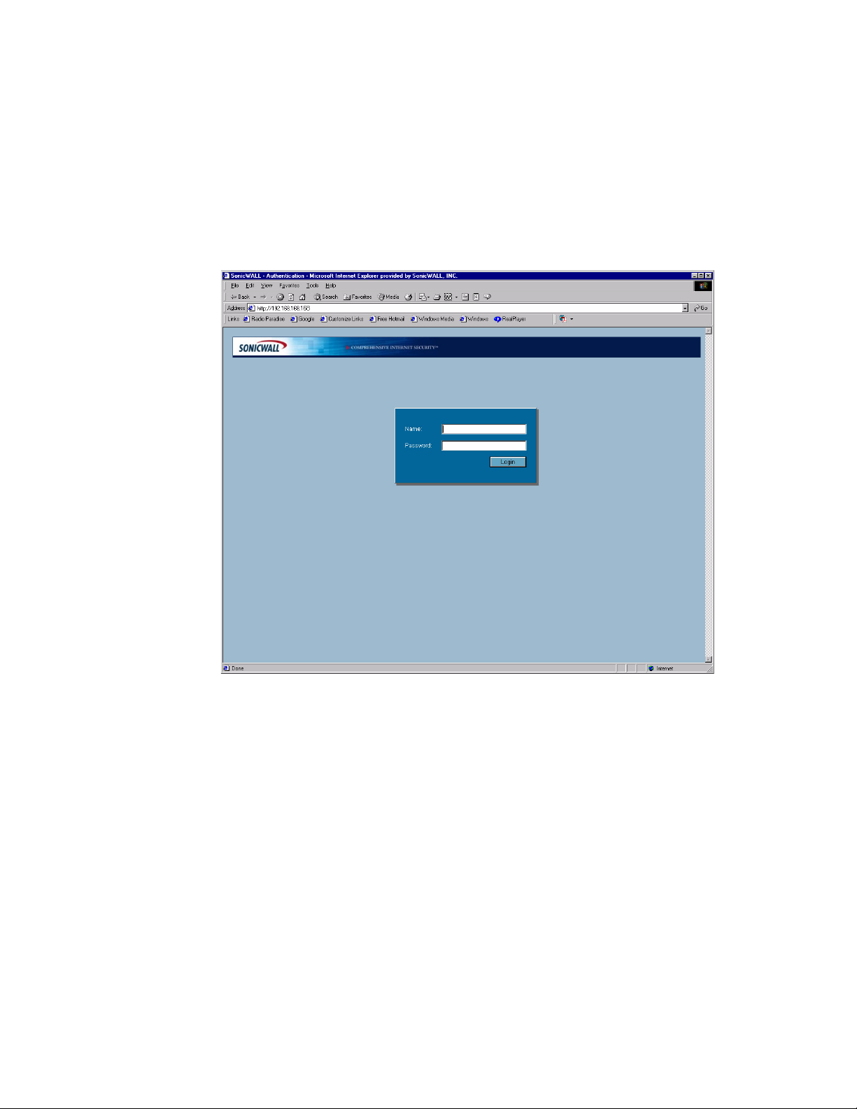
To begin the configuration of your SonicWALL security appliance, you must log into the SonicWALL
security appliance using a Web browser and the SonicWALL security appliance default LAN IP
address, 192.168.168.168. Follow the instructions below:
1
Launch your Web browser.
2
Enter 192.168.168.168 in the Location or Address field.
3
The first time you log into the SonicWALL Management Interface, the Setup Wizard is
automatically displayed for configuring your WAN (Internet) and LAN setup.
Cross Reference: See Chapter 49 Configuring Internet Connecitivity using the Setup Wizard.
Â
Troubleshooting
If you cannot connect to the SonicWALL security appliance, check the following:
• Did you correctly enter the SonicWALL security appliance default LAN IP address in your browser
window?
• Is the SonicWALL security appliance connected to the same network as your computer?
• Have you changed the TCP/IP network settings on your computer?
• Try pinging the 192.168.168.168 LAN IP address of the SonicWALL security appliance from your
computer. It should reply, assuming that you are using the correct TCP/IP network settings and
have a good ethernet connection. If it does reply, try again with the web browser to
192.168.168.168.
SONICWALL SONICOS ENHANCED 2.5 ADMINISTRATOR’S GUIDE
11
Page 27
C
HAPTER
2:
Getting Started
Using the Management Interface
The SonicWALL’s Web Management Interface provides a easy-to-use graphical interface for
configuring your SonicWALL. SonicWALL management functions are performed through a Web
browser.
Tip: Microsoft Internet Explorer 5.0 or higher, or, Netscape Navigator 4.5 or higher are two
9
recommended Web browsers.
Navigating the Management Interface
Navigating the SonicWALL Management Interface includes a hierarchy of menu buttons on the
navigation bar (left side of window). The SonicOS Enhanced menu buttons on the navigation bar
include:
• System
• Network
• Wireless
• Firewall
• VPN
• Users
• Hardware Failover
• Security Services
• Log
• Wizards
• Help
• Logout
When you click a menu button, related management functions are displayed as submenu items in the
navigation bar. To navigate to a submenu page, click the link. When you click a menu button, the first
submenu item page is displayed.
Applying Changes
Click the Apply button at the top right corner of the SonicWALL Management Interface to save any
configuration changes you made on the page.
12
SONICWALL SONICOS ENHANCED 2.5 ADMINISTRATOR’S GUIDE
Page 28

If the settings are contained in a secondary window within the Management Interface, when you click
OK, the settings are automatically applied to the SonicWALL.
Getting Help
Each SonicWALL includes Web-based online help available from the Management Interface. Clicking
the question mark ? button on the top right corner of every page accesses the
context-sensitive help for the page.
Alert: SonicWALL online help requires Internet connectivity.
S
Logging Out
The Logout button at the bottom of the menu bar terminates the Management Interface session and
displays the Login page.
SONICWALL SONICOS ENHANCED 2.5 ADMINISTRATOR’S GUIDE
13
Page 29

C
HAPTER
2:
Getting Started
14
SONICWALL SONICOS ENHANCED 2.5 ADMINISTRATOR’S GUIDE
Page 30

P
ART
2
Part 2System
SONICWALL SONICOS ENHANCED 2.5 ADMINISTRATOR’S GUIDE
15
Page 31

:
16
SONICWALL SONICOS ENHANCED 2.5 ADMINISTRATOR’S GUIDE
Page 32

Chapter 3: Viewing Status Information
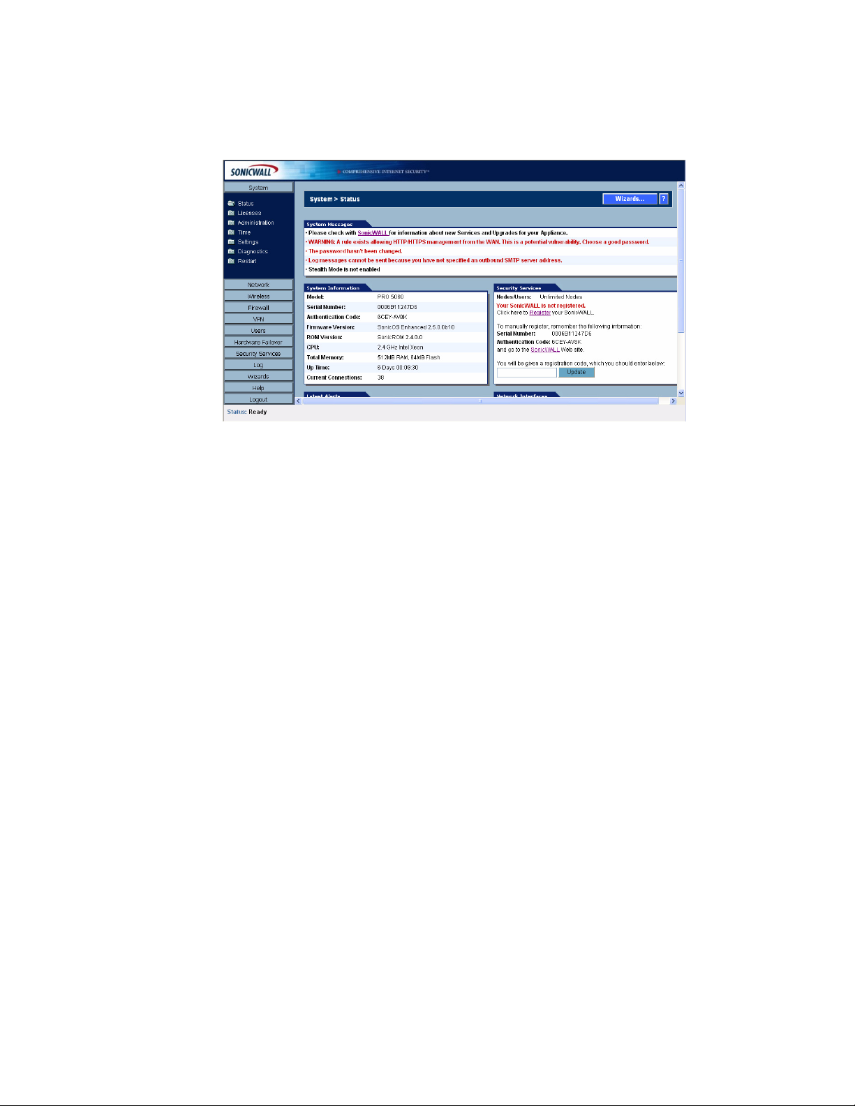
System > Status
The System>Status page provides a comprehensive collection of information and links to help you
manage your SonicWALL security appliance and SonicWALL Security Services licenses. It includes
status information about your SonicWALL security appliance organized into five sections: System
Messages, System Information, Security Services, Latest Alerts, and Network Interfaces as
well as the Wizards button for accessing the SonicWALL Configuration Wizard.
System > Status
C
HAPTER
3
SONICWALL SONICOS ENHANCED 2.5 ADMINISTRATOR’S GUIDE
17
Page 33

C
HAPTER
3:
Viewing Status Information
Wizards
The Wizards button on the System>Status page provides access to the SonicWALL Configuration
Wizard, which allows you to easily configure the SonicWALL security appliance using the following
sub-wizards:
• Setup Wizard - This wizard helps you quickly configure the SonicWALL security appliance to
secure your Internet (WAN) and LAN connections.
• Public Server Wizard - This wizard helps you quickly configure the SonicWALL security appliance
to provide public access to an internal server, such as a Web or E-mail server.
• VPN Wizard - This wizard helps you create a new site-to-site VPN Policy or configure the WAN
GroupVPN to accept VPN connections from SonicWALL Global VPN Clients.
Cross Reference: For more information on using the SonicWALL Configuration Wizard, see Part 11
Â
Wizards.
System Messages
Any information considered relating to possible problems with configurations on the SonicWALL
security appliance such as password, log messages, as well as notifications of SonicWALL Security
Services offers, new firmware notifications, and upcoming Security Service s expirations are
displayed in the System Messages section.
System Information
The following information is displayed in this section:
• Model - type of SonicWALL security appliance product
• Serial Number - also the MAC address of the SonicWALL security appliance
• Authentication Code - the alphanumeric code used to authenticate the SonicWALL security
appliance on the registration database at <https://www.mysonicwall.com>.
• Firmware Version - the firmware version loaded on the SonicWALL security appliance.
• ROM Version - indicates the ROM version.
•CPU - displays the type and speed of the SonicWALL security appliance processor.
• Total Memory - indicates the amount of RAM and flash memory.
• Up Time - the length of time, in days, hours, and seconds the SonicWALL security appliance is
active.
• Current Connections - the number of network connections currently existing on the
SonicWALL security appliance.
• Registration Code - the registration code is generated when your SonicWALL security appliance
is registered at <http://www.mysonicwall.com>.
Latest Alerts
18
Any messages relating to system errors or attacks are displayed in this section. Attack messages
include AV Alerts, forbidden e-mail attachments, fraudulent certificates, etc. System errors include
WAN IP changed and encryption errors. Clicking the blue arrow displays the Log>Log View page.
Cross Reference: For more information on SonicWALL security appliance logging, see Part 10 Log.
Â
SONICWALL SONICOS ENHANCED 2.5 ADMINISTRATOR’S GUIDE
Page 34

Registration and Security Services
Once you’ve established your Internet connection, you can register your security appliance at
mySonicWALL.com as well as activate SonicWALL Security Services. Any bundled services included
with your SonicWALL security appliance are automatically activated when your register.
You need a mySonicWALL.com account to register your security appliance or activate SonicWALL
Security Services. You can create a mySonicWALL.com account directly from the SonicWALL
Management Interface. If your security appliance is connected to the Internet, and you have a
mySonicWALL.com account, you can register the security appliance and activate SonicWALL Security
Services directly from the Management Interface.
Registering Your SonicWALL Security Appliance
If your security appliance is not registered, the following message is displayed in the Security
Services folder on the System>Status page in the SonicWALL Management Interface: Your
SonicWALL is not registered. Click here to Register
You can also manually register your security appliance at the www.mySonicWALL.com site by using
the Serial Number and Authentication Code displayed in the Security Services section. Click the
SonicWALL
after you have registered your security appliance. Enter the registration code in the field below the
You will be given a registration code, which you should enter below heading, then click Update.
link to access your mySonicWALL.com account. You will be given a registration code
System > Status
your SonicWALL Security Appliance.
The following sections explain how to create a mySonicWALL.com account from the SonicWALL
Management Interface, if you don’t have an account, and how to register your security appliance
directly from the Management Interface.
mySonicWALL.com
mySonicWALL.com delivers a convenient, one-stop resource for registration, activation, and
management of your SonicWALL products and services. Your mySonicWALL.com account provides
a single profile to do the following:
• Register your SonicWALL security appliances
• Purchase/Activate SonicWALL Security Services and Upgrades
• Receive SonicWALL firmware and security service updates and alerts
• Manage (change or delete) your SonicWALL security services
• Access SonicWALL Technical Support
Creating a mySonicWALL.com account is easy and FREE. Simply complete an online registration
form. Once your account is created, you can register SonicWALL security appliance and activate
SonicWALL Security Services associated with the security appliance.
Your mySonicWALL.com account is accessible from any Internet connection with a Web browser
using the HTTPS (Hypertext Transfer Protocol Secure) protocol to protect your sensitive information.
You can also access mySonicWALL.com license and registration services directly from the
SonicWALL management interface for increased ease of use and simplified services activation.
Tip: For more information on mySonicWALL.com, access the online help available at
9
https://www.mysonicwall.com.
Note: mySonicWALL.com registration information is not sold or shared with any other company.
SONICWALL SONICOS ENHANCED 2.5 ADMINISTRATOR’S GUIDE
19
Page 35

C
HAPTER
3:
Viewing Status Information
Creating Your mySonicWALL.com Account
If you already have a mySonicWALL.com account, skip this section. To create a mySonicWALL.com
account from the SonicWALL Management Interface, follow these steps:
In the Security Services folder on the System>Status page in the SonicWALL Management
Interface, click the here link in Your security appliance is not registered. Click here to Register
your security appliance. The mySonicWALL.com Login page is displayed.
1
Click the here link in If you do not have a mySonicWALL account, please click here to create
one. The mySonicWALL.com account form is displayed.
2
Enter in your information in the Account Information, Personal Information and Preferences
fields. All fields marked with an * are required fields.
Alert: Remember your username and password to access your mySonicWALL.com account.
S
S
3
Click Submit after completing the mySonicWALL.com account form.
4
Review your account information. If the information is correct, click OK. You will receive a
subscription code by e-mail from SonicWALL. This code is required to complete the activation of
your new account.
Alert: Your new account must be activated with the subscription code within 72 hours of receiving the
code.
5
After you receive your subscription code, in the Security Services folder on the System>Status
page in the SonicWALL Management Interface, click the here link in Your SonicWALL is not
registered. Click here to Register
6
In the mySonicWALL.com Login page, enter your mySonicWALL.com account username and
password, and click Submit. You are prompted for the subscription code.
7
Enter your subscription code and click Submit. Your mySonicWALL.com account is activated.
your SonicWALL.
20
SONICWALL SONICOS ENHANCED 2.5 ADMINISTRATOR’S GUIDE
Page 36

System > Status
Registering the SonicWALL Security Appliance from the Management Interface
If you have a mySonicWALL.com account, follow these steps to register your SonicWALL security
appliance:
1
Click the here link to automatically register your SonicWALL security appliance. The
mySonicWALL.com Login page is displayed.
2
Type your mySonicWALL.com username and password in the User Name and Password fields
and click Submit.
3
Type in a “friendly name” for your SonicWALL security appliance in the Friendly Name field. A
friendly name is used to help identify your SonicWALL security appliance, such as its location.
4
Click Submit. Your SonicWALL security appliance is now registered.
Alert: Make sure the DNS and Time settings on your security appliance are correct when you register
S
the device.
Security Services
If your SonicWALL security appliance is registered, the Security Services section provides a list of
currently Licensed SonicWALL Security Services and the number of licenses available and in use.
Clicking the blue icon displays the System>Licenses page in the SonicWALL Web Management
Interface. SonicWALL Security Services and SonicWALL security appliance registration is managed
by mySonicWALL.com.
Cross Reference: For more information on SonicWALL Security Services, see Part 9 Security
Â
Services.
SONICWALL SONICOS ENHANCED 2.5 ADMINISTRATOR’S GUIDE
21
Page 37

C
HAPTER
3:
Viewing Status Information
Network Interfaces
Network Interfaces displays information about the interfaces for your SonicWALL security appliance.
Clicking the blue arrow displays the Network>Settings page for configuring your Network settings.
The available interfaces displayed in the Network Interfaces section depends on the SonicWALL
security appliance model.
SonicWALL PRO 2040
•X0) LAN - IP address and network speed.
•(X1) WAN - IP address, network speed and devices connected to the WAN interface.
•X2 - X3 - user-defined interfaces.
SonicWALL PRO 3060/PRO 4060
•(X0) LAN - IP address and network speed.
•(X1) WAN - IP address, network speed and devices connected to the WAN interface.
•X2 - X5 - user-defined interfaces.
SonicWALL PRO 5060
The SonicWALL PRO 5060 interfaces support up to 1 Gbps.
•(X0) LAN - IP address and network speed.
•(X1) WAN - IP address, network speed and devices connected to the WAN interface.
•X2 - X5 - user-defined interfaces.
SonicWALL TZ 170
• LAN (LAN) - IP address and network speed.
•WAN (WAN) - IP address, network speed and devices connected to the WAN interface.
• OPT (Unassigned) - user definable interface.
22
SONICWALL SONICOS ENHANCED 2.5 ADMINISTRATOR’S GUIDE
Page 38

Chapter 4: Managing SonicWALL Security
System > Licenses
System > Licenses
C
HAPTER
4
Services Licenses
The System>Licenses page provides links to activate, upgrade, or renew SonicWALL Security
Services licenses. From this page in the SonicWALL Management Interface, you can manage all the
SonicWALL Security Services licensed for your SonicWALL security appliance. The information listed
in the Security Services Summary table is updated from your mySonicWALL.com account. This
chapter describes managing SonicWALL Security Services licenses from your mySonicWALL.com
account directly from the SonicWALL Management Interface. The System>Licenses page also
includes links to FREE trials of SonicWALL Security Services.
Security Services Summary
The Security Services Summary table lists the available and activated security services on the
SonicWALL security appliance. The Security Service column lists all the available SonicWALL
Security Services and upgrades available for the SonicWALL security appliance. The Status column
indicates is the security service is activated (Licensed), available for activation (Not Licensed), or no
SONICWALL SONICOS ENHANCED 2.5 ADMINISTRATOR’S GUIDE
23
Page 39
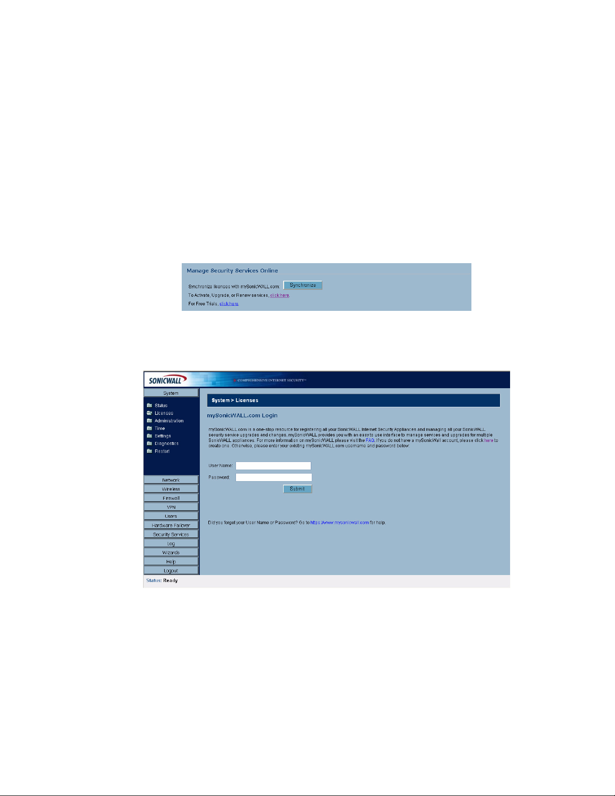
C
HAPTER
4:
Managing SonicWALL Security Services Licenses
longer active (Expired). The number of nodes/users allowed for the license is displayed in the Count
column. The Expiration column displays the expiration date for any Licensed Security Service.
The information listed in the Security Services Summary table is updated from your
mySonicWALL.com account the next time the SonicWALL security appliance automatically
synchronizes with your mySonicWALL.com account (once a day) or you can click the link in To
synchronize licenses with mySonicWALL.com click here in the Manage Security Services
Online section.
Cross Reference: For more information on SonicWALL Security Services, see Part 9 Security
Â
Services.
Manage Security Services Online
To activate, upgrade, or renew services, click the link in To Activate, Upgrade, or Renew services,
click here. Click the link in To synchronize licenses with mySonicWALL.com click here to
synchronize your mySonicWALL.com account with the Security Services Summary table.
You can also get free trial subscriptions to SonicWALL Content Filter Service and Network Anti-Virus
by clicking the For Free Trials click here link. When you click these links, the mySonicWALL.com
Login page is displayed.
24
SONICWALL SONICOS ENHANCED 2.5 ADMINISTRATOR’S GUIDE
Page 40

System > Licenses
Enter your mySonicWALL.com account username and password in the User Name and Password
fields and click Submit. The Manage Services Online page is displayed with licensing information
from your mySonicWALL.com account.
Manual Upgrade
Manual Upgrade allows you to activate your services by typing the service activation key supplied
with the service subscription not activated on mySonicWALL.com. Type the activation key from the
product into the Enter upgrade key field and click Submit.
Manual Upgrade for Closed Environments
If your SonicWALL security appliance is deployed in a high security environment that does not allow
direct Internet connectivity from the SonicWALL security appliance, you can enter the encrypted
license key information from http://www.mysonicwall.com manually on the System>Licenses page in
the SonicWALL Management Interface.
Note: Manual upgrade of the encrypted License Keyset is only for Closed Environments. If your
SonicWALL security appliance is connected to the Internet, it is recommended you use the automatic
registration and Security Services upgrade features of your SonicWALL security appliance.
From a Computer Connected to the Internet
1. Make sure you have an account at http://www.mysonicwall.com and your SonicWALL security
appliance is registered to the account before proceeding.
2. After logging into www.mysonicwall.com, click on your registered SonicWALL security appliance
listed in Registered SonicWALL Products.
SONICWALL SONICOS ENHANCED 2.5 ADMINISTRATOR’S GUIDE
25
Page 41

C
HAPTER
4:
Managing SonicWALL Security Services Licenses
3. Click the View License Keyset link. The scrambled text displayed in the text box is the License
Keyset for the selected SonicWALL security appliance and activated Security Services. Copy the
Keyset text for pasting into the System>Licenses page or print the page if you plan to manually type
in the Keyset into the SonicWALL security appliance.
From the Management Interface of your SonicWALL Security Appliance
4. Make sure your SonicWALL security appliance is running SonicOS Standard or Enhanced 2.1 (or
higher).
5. Paste (or type) the Keyset (from the step 3) into the Keyset field in the Manual Upgrade section of
the System>Licenses page (SonicOS).
6. Click the Submit or the Apply button to update your SonicWALL security appliance. The status
field at the bottom of the page displays The configuration has been updated.
7. You can generate the System>Diagnostics>Tech Support Report to verify the upgrade details.
Note: After the manual upgrade, the System>Licenses page does not contain any registration and
9
upgrade information.
Tip: The warning message: SonicWALL Registration Update Needed. Please update your
registration
SonicWALL security appliance. Ignore this message.
information remains on the System>Status page after you have registered your
26
SONICWALL SONICOS ENHANCED 2.5 ADMINISTRATOR’S GUIDE
Page 42

Chapter 5: Configuring SonicWALL Security
Appliance Administration Settings
System > Administration
System > Administration
C
HAPTERW
5
The System Administration page provides settings for the configuration of SonicWALL security
appliance for secure and remote management. You can manage the SonicWALL using a variety of
methods, including HTTPS, SNMP or SonicWALL Global Management System (SonicWALL GMS).
Firewall Name
The Firewall Name uniquely identifies the SonicWALL security appliance and defaults to the serial
number of the SonicWALL. The serial number is also the MAC address of the unit. To change the
Firewall Name, type a unique alphanumeric name in the Firewall Name field. It must be at least 8
characters in length.
SONICWALL SONICOS ENHANCED 2.5 ADMINISTRATOR’S GUIDE
27
Page 43
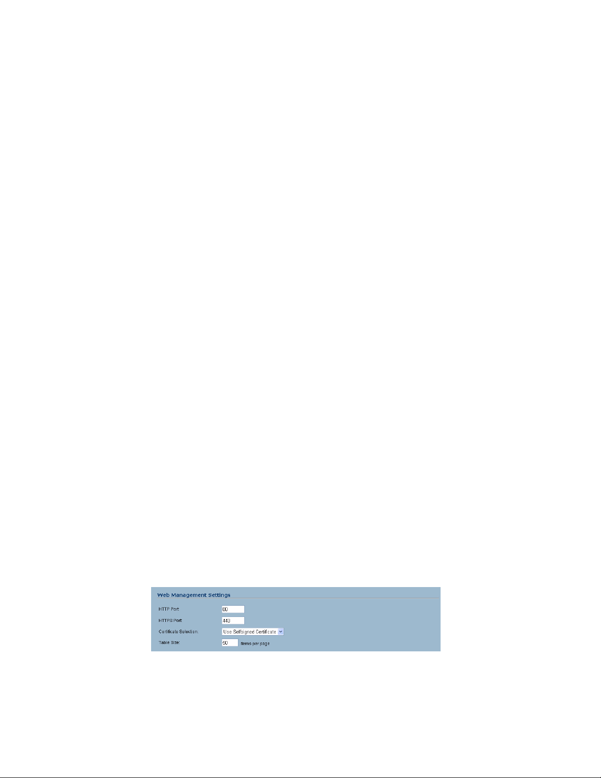
C
HAPTER
5:
Configuring SonicWALL Security Appliance Administration Settings
Administrator Name & Password
The Administrator Name can be changed from the default setting of admin to any word using
alphanumeric characters up to 32 characters in length. To create an new administrator name, type the
new name in the Administrator Name field. Click Apply for the changes to take effect on the
SonicWALL.
Changing the Administrator Password
To set a new password for SonicWALL Management Interface access, type the old password in the
Old Password field, and the new password in the New Password field. Type the new password
again in the Confirm New Password field and click Apply. Once the SonicWALL security appliance
has been updated, a message confirming the update is displayed at the bottom of the browser
window.
Tip: It’s recommended you change the default password password to your own custom password.
9
Login Security
The Log out the Administrator Inactivity Timeout after inactivity of (minutes) setting allows you
to set the length of inactivity time that elapses before you are automatically logged out of the
Management Interface. By default, the SonicWALL security appliance logs out the administrator after
5 minutes of inactivity. The inactivity timeout can range from 1 to 99 minutes. Click Apply, and a
message confirming the update is displayed at the bottom of the browser window.
Tip: If the Administrator Inactivity Timeout is extended beyond 5 minutes, you should end every
9
management session by clicking Logout to prevent unauthorized access to the SonicWALL security
appliance’s Management Interface.
Enable Administrator/User Lockout
You can configure the SonicWALL security appliance to lockout an administrator or a user if the login
credentials are incorrect. Select the Enable Administrator/User Lockout on login failure checkbox
to prevent users from attempting to log into the SonicWALL security appliance without proper
authentication credentials. Type the number of failed attempts before the user is locked out in the
Failed login attempts per minute before lockout field. Type the length of time that must elapse
before the user attempts to log into the SonicWALL again in the Lockout Period (minutes) field.
Alert: If the administrator and a user are logging into the SonicWALL using the same source IP
S
address, the administrator is also locked out of the SonicWALL. The lockout is based on the source
IP address of the user or administrator.
Web Management Settings
28
The SonicWALL security appliance can be managed using HTTP or HTTPS and a Web browser. Both
HTTP and HTTPS are enabled by default. The default port for HTTP is port 80, but you can configure
access through another port. Type the number of the desired port in the Port field, and click Apply.
However, if you configure another port for HTTP management, you must include the port number
SONICWALL SONICOS ENHANCED 2.5 ADMINISTRATOR’S GUIDE
Page 44

System > Administration
when you use the IP address to log into the SonicWALL security applaince. For example, if you
configure the port to be 76, then you must type <LAN IP Address>:76 into the Web browser, i.e.
<http://192.168.168.1:76>. The default port for HTTPS management is 443.
You can add another layer of security for logging into the SonicWALL security appliance by changing
the default port. To configure another port for HTTPS management, type the preferred port number
into the Port field, and click Update. For example, if you configure the HTTPS Management Port to
be 700, then you must log into the SonicWALL using the port number as well as the IP address, for
example, <https://192.168.168.1:700> to access the SonicWALL.
The Certificate Selection menu allows you to use a self-signed certificate (Use Self-signed
Certificate), which allows you to continue using a certificate without downloading a new one each
time you log into the SonicWALL security appliance. You can also choose Import Certificate to
select an imported certificate from the VPN>Local Certificates page to use for authentication to the
Management Interface.
Changing the Default Size for SonicWALL Management Interface Tables
The SonicWALL Management Interface allows you to control the display of large tables of information
across all tables in the management Interface; for example the table on the Network>Address
Objects page.
You can change the default table page size in all tables displayed in the SonicWALL Management
Interface from the default 50 items per page to any size ranging from 1 to 5,000 items.
To change the default table size:
1
Enter the maximum table size number in the Table Size field.
2
Click Apply.
Advanced Management
You can manage the SonicWALL security appliance using SNMP or SonicWALL Global Management
System. The following sections explain how to configure the SonicWALL for management by these
two options.
SONICWALL SONICOS ENHANCED 2.5 ADMINISTRATOR’S GUIDE
29
Page 45

C
HAPTER
5:
Configuring SonicWALL Security Appliance Administration Settings
Cross Reference: For more information on SonicWALL Global Management System, go to
Â
http://www.sonicwall.com.
Enabling SNMP Management
SNMP (Simple Network Management Protocol) is a network protocol used over User Datagram
Protocol (UDP) that allows network administrators to monitor the status of the SonicWALL security
appliance and receive notification of critical events as they occur on the network. The SonicWALL
security appliance supports SNMP v1/v2c and all relevant Management Information Base II (MIB)
groups except egp and at. The SonicWALL security appliance replies to SNMP Get commands for
MIBII via any interface and supports a custom SonicWALL MIB for generating trap messages. The
custom SonicWALL MIB is available for download from the SonicWALL Web site and can be loaded
into third-party SNMP management software such as HP Openview, Tivoli, or SNMPC.
Configuring SNMP Management
To enable SNMP on the SonicWALL security appliance, log into the Management interface and click
System, then Administration. Select the Enable SNMP checkbox, and then click Configure.
1
Type the host name of the SonicWALL security appliance in the System Name field.
2
Type the network administrator’s name in the System Contact field.
3
Type an e-mail address, telephone number, or pager number in the System Location field.
4
Type a name for a group or community of administrators who can view SNMP data in the Get
Community Name field.
5
Type a name for a group or community of administrators who can view SNMP traps in the Trap
Community Name field.
6
Type the IP address or host name of the SNMP management system receiving SNMP traps in the
Host 1 through Host 4 fields. You must configure at least one IP address or host name, but up to
four addresses or host names can be used.
7
Click OK.
Configuring Log/Log Settings for SNMP
Trap messages are generated only for the alert message categories normally sent by the SonicWALL
security appliance. For example, attacks, system errors, or blocked Web sites generate trap
messages. If none of the categories are selected on the Log>Settings page, then no trap messages
are generated.
Configuring SNMP as a Service and Adding Rules
By default, the SonicWALL security appliance responds only to Get SNMP messages received on its
LAN interface. Appropriate rules must be configured to allow SNMP traffic to and from the WAN
interface. SNMP trap messages can be sent via the LAN or WAN.
Cross Reference: For instructions on adding services and rules to the SonicWALL security appliance,
Â
see Part 5 Firewall.
If your SNMP management system supports discovery, the SonicWALL security appliance agent
automatically discover the SonicWALL security appliance on the network. Otherwise, you must add
the SonicWALL security appliance to the list of SNMP-managed devices on the SNMP management
system.
30
SONICWALL SONICOS ENHANCED 2.5 ADMINISTRATOR’S GUIDE
Page 46

System > Administration
Enable GMS Management
You can configure the SonicWALL security appliance to be managed by SonicWALL Global
Management System (SonicWALL GMS).
Configuring the SonicWALL Security Appliance for GMS Management
To configure the SonicWALL security appliance for GMS management:
1
Select the Enable Management using GMS checkbox, then click Configure. The Configure
GMS Settings window is displayed.
2
Enter the host name or IP address of the GMS Console in the GMS Host Name or IP Address
field.
3
Enter the port in the GMS Syslog Server Port field. The default value is 514.
4
Select Send Heartbeat Status Messages Only to send only heartbeat status instead of log
messages.
5
Select GMS behind NAT Device if the GMS Console is placed behind a device using NAT on the
network. Type the IP address of the NAT device in the NAT Device IP Address field.
6
Select one of the following GMS modes from the Management Mode menu.
IPSEC Management Tunnel - Selecting this option allows the SonicWALL security appliance to
be managed over an IPSec VPN tunnel to the GMS management console. The default IPSec VPN
settings are displayed. Select GMS behind NAT Device if applicable to the GMS installation, and
SONICWALL SONICOS ENHANCED 2.5 ADMINISTRATOR’S GUIDE
31
Page 47

C
HAPTER
5:
Configuring SonicWALL Security Appliance Administration Settings
enter the IP address in the NAT Device IP Address field. The default VPN policy settings are
displayed at the bottom of the Configure GMS Settings window.
Existing Tunnel - If this option is selected, the GMS server and the SonicWALL security appliance
already have an existing VPN tunnel over the connection. Enter the GMS host name or IP address
in the GMS Host Name or IP Address field. Enter the port number in the Syslog Server Port
field.
HTTPS - If this option is selected, HTTPS management is allowed from two IP addresses: the
GMS Primary Agent and the Standby Agent IP address. The SonicWALL security appliance also
sends encrypted syslog packets and SNMP traps using 3DES and the SonicWALL security
appliance administrator’s password. The following configuration settings for HTTPS management
mode are displayed:
32
Send Syslog Messages in Cleartext Format - Sends heartbeat messages as cleartext.
Send Syslog Messages to a Distributed GMS Reporting Server - Sends regular heartbeat
messages to both the GMS Primary and Standby Agent IP address. The regular heartbeat
messages are sent to the specified GMS reporting server and the reporting server port.
GMS Reporting Server IP Address - Enter the IP address of the GMS Reporting Server, if the
server is separate from the GMS management server.
GMS Reporting Server Port - Enter the port for the GMS Reporting Server. The default value is
514
7
Click OK.
SONICWALL SONICOS ENHANCED 2.5 ADMINISTRATOR’S GUIDE
Page 48

VPN Client Download URL
The VPN Client Download URL provides a field for entering the URL address of a site for
downloading the SonicWALL Global VPN Client application, when a user is prompted to use the
Global VPN Client for access to the network.
The default URL http://help.mysonicwall.com/applications/vpnclient displays the SonicWALL Global
VPN Client download site. You can point to any URL where you provide the SonicWALL Global VPN
Client application.
System > Administration
SONICWALL SONICOS ENHANCED 2.5 ADMINISTRATOR’S GUIDE
33
Page 49

C
HAPTER
5:
Configuring SonicWALL Security Appliance Administration Settings
34
SONICWALL SONICOS ENHANCED 2.5 ADMINISTRATOR’S GUIDE
Page 50

Chapter 6: Configuring Time Settings
System > Time
The System>Time page defines the time and date settings to time stamp log events, to automatically
update SonicWALL Security Services, and for other internal purposes. iBy default, the SonicWALL
security appliance uses an internal list of public NTP servers to automatically update the time.
Network Time Protocol (NTP) is a protocol used to synchronize computer clock times in a network of
computers. NTP uses Coordinated Universal Time (UTC) to synchronize computer clock times to a
millisecond, and sometimes to a fraction of a millisecond.
System > Time
C
HAPTER
6
SONICWALL SONICOS ENHANCED 2.5 ADMINISTRATOR’S GUIDE
35
Page 51

C
HAPTER
6:
Configuring Time Settings
System Time
To select your time zone and automatically update the time, choose the time zone from the Time
Zone menu. The Use NTP to set time automatically is activated by default to use the NTP (Network
Time Protocol) to set time automatically. If you want to set your time manually, uncheck this setting.
Select the time in the 24-hour format using the Time (hh:mm:ss) menus and the date from the Date
menus. Automatically adjust clock for daylight saving changes is activated by default to enable
automatic adjustments for daylight savings time.
Selecting Display UTC in logs (instead of local time) specifies the use universal time (UTC) rather
than local time for log events.
Selecting Display time in International format displays the date in International format, with the day
preceding the month.
After selecting your System Time settings, click Apply.
NTP Settings
Network Time Protocol (NTP) is a protocol used to synchronize computer clock times in a network of
computers. NTP uses Coordinated Universal Time (UTC) to synchronize computer clock times to a
millisecond, and sometimes, to a fraction of a millisecond.
9
Tip: The SonicWALL security appliance uses an internal list of NTP servers so manually entering a
NTP server is optional.
Select Use NTP to set time automatically if you want to use your local server to set the SonicWALL
security appliance clock. You can also configure Update Interval (minutes) for the NTP server to
update the SonicWALL security appliance. The default value is 60 minutes.
To add an NTP server to the SonicWALL security appliance configuration
1
Click Add. The Add NTP Server window is displayed.
2
Type the IP address of an NTP server in the NTP Server field.
3
Click OK.
4
Click Apply on the System>Time page to update the SonicWALL security appliance.
To delete an NTP server, highlight the IP address and click Delete. Or, click Delete All to delete all
servers.
36
SONICWALL SONICOS ENHANCED 2.5 ADMINISTRATOR’S GUIDE
Page 52

Chapter 7: Managing SonicWALL Security
System > Settings
System > Settings
C
HAPTER
7
Appliance Firmware
This System>Settings page allows you to manage your SonicWALL security appliance’s SonicOS
versions and preferences.
Settings
Import Settings
To import a previously saved preferences file into the SonicWALL security appliance, follow these
instructions:
1
Click Import Settings to import a previously exported preferences file into the SonicWALL
security appliance. The Import Settings window is displayed.
2
Click Browse to locate the file which has a *.exp file name extension.
SONICWALL SONICOS ENHANCED 2.5 ADMINISTRATOR’S GUIDE
37
Page 53

C
HAPTER
7:
Managing SonicWALL Security Appliance Firmware
3
Select the preferences file.
4
Click Import, and restart the firewall.
Export Settings
To export configuration settings from the SonicWALL security appliance, use the instructions below:
1
Click Export Settings.
2
Click Export.
3
Click Save, and then select a location to save the file. The file is named “sonicwall.exp” but can be
renamed.
4
Click Save. This process can take up to a minute. The exported preferences file can be imported
into the SonicWALL security appliance if it is necessary to reset the firmware.
Firmware Management
The Firmware Management section provides settings that allow for easy firmware upgrade and
preferences management. The Firmware Management section allows you to:
• Upload and download firmware images and system settings.
• Boot to your choice of firmware and system settings.
• Manage system backups.
• Easily return your SonicWALL security appliance to the previous system state.
Note: SonicWALL security appliance SafeMode, which uses the same settings used Firmware
Management, provides quick recovery from uncertain configuration states.
Automatic Notification of New Firmware
To receive automatic notification of new firmware, select the Notify me when new firmware is
available check box. If you enable this feature, the SonicWALL security appliance sends a status
message to the SonicWALL firmware server daily with the following information:
• SonicWALL Serial Number
• Product Type
• Current Firmware Version
• Language
• Currently Available Memory
• ROM Version
Alert: After the initial 90 days from purchase, firmware updates are available only to registered users
S
with a valid support contract. You must register your SonicWALL at
<https://www.mysonicwall.com>.
If a new firmware version becomes available, the message New SonicWALL Firmware Version is
available. Click here for details on this latest release appears in System Messages on the
System>Status page. Clicking the here link displays the Release Notes for the new firmware.
38
SONICWALL SONICOS ENHANCED 2.5 ADMINISTRATOR’S GUIDE
Page 54

Firmware Management Table
The Firmware Management table displays the following information:
• Firmware Image - In this column, four types of firmware images are listed:
Current Firmware - firmware currently loaded on the SonicWALL security appliance.
Current Firmware with Factory Default Settings - rebooting using this firmware image resets
the SonicWALL security appliance to its default IP addresses, username, and password.
Uploaded Firmware - the latest uploaded version from mySonicWALL.com.
Uploaded Firmware with Factory Default Settings - the latest version uploaded with factory
default settings.
System Backup - a firmware image created by clicking Create Backup.
• Version - the firmware version.
•Date - the day, date, and time of downloading the firmware.
•Size - the size of the firmware file in Megabytes (MB).
• Download - clicking the icon saves the firmware file to a new location on your computer or
network. Only uploaded firmware can be saved to a different location.
• Boot - clicking the icon reboots the SonicWALL security appliance with the firmware version listed
in the same row.
System > Settings
S
S
Alert: Clicking Boot next to any firmware image overwrites the existing current firmware image
making it the Current Firmware image. On the TZ 170, the uploaded firmware images are removed
from the table after rebooting the SonicWALL security appliance.
Alert: When uploading firmware to the SonicWALL security appliance, you must not interrupt the Web
browser by closing the browser, clicking a link, or loading a new page. If the browser is interrupted,
the firmware may become corrupted.
SONICWALL SONICOS ENHANCED 2.5 ADMINISTRATOR’S GUIDE
39
Page 55

C
HAPTER
7:
Managing SonicWALL Security Appliance Firmware
Updating Firmware Manually
Click Upload New Firmware to upload new firmware to the SonicWALL security appliance. The
Upload Firmware window is displayed. Browse to the firmware file located on your local drive. Click
Upload to upload the new firmware to the SonicWALL security appliance.
Creating a Backup Firmware Image
When you click Create Backup, the SonicWALL security appliance takes a “snapshot” of your current
system state, firmware and configuration preferences, and makes it the new System Backup firmware
image. Clicking Create Backup overwrites the existing System Backup firmware image as
necessary.
SafeMode - Rebooting the SonicWALL Security Appliance
SafeMode allows easy firmware and preferences management as well as quick recovery from
uncertain configuration states. It is no longer necessary to reset the firmware by pressing and holding
the Reset button on the appliance. Pressing the Reset button for one second launches the
SonicWALL security appliance into SafeMode. SafeMode allows you to select the firmware version to
load and reboot the SonicWALL security appliance.
Note: Because there are hardware differences between the TZ 170 and the PRO 2040/PRO 3060/
PRO 4060/PRO 5060, Safe Mode on the TZ 170 cannot store as many firmware images as the PRO
2040/3060. After rebooting, the TZ 170 does not retain uploaded firmware images.
To access the SonicWALL security appliance using SafeMode, press the Reset button for 1 second.
After the SonicWALL security appliance reboots, open your Web browser and enter the current IP
address of the SonicWALL security appliance or the default IP address: 192.168.168.168. The
SafeMode page is displayed:
SafeMode allows you to do any of the following:
• Upload and download firmware images to the SonicWALL security appliance.
• Upload and download system settings to the SonicWALL security appliance.
• Boot to your choice of firmware options.
• Create a system backup file.
• Return your SonicWALL security appliance to a previous system state.
System Information
System Information for the SonicWALL security appliance is retained and displayed in this section.
40
SONICWALL SONICOS ENHANCED 2.5 ADMINISTRATOR’S GUIDE
Page 56

Firmware Management
The Firmware Management table has the following columns:
• Firmware Image - In this column, five types of firmware images are listed:
- Current Firmware, firmware currently loaded on the SonicWALL security appliance
- Current Firmware with Factory Default Settings, rebooting using this firmware image resets
the SonicWALL security appliance to its default IP addresses, user name, and password
- Uploaded Firmware, the last version uploaded from mysonicwall.com
- Uploaded Firmware with Factory Default Settings, rebooting using this firmware image resets
the SonicWALL security appliance to its default IP addresses, user name, and password
- System Backup, a firmware image created by clicking Create Backup.
• Version - The firmware version is listed in this column.
•Date - The day, date, and time of downloading the firmware.
•Size - The size of the firmware file in Megabytes (MB).
• Download - Clicking the icon saves the firmware file to a new location on your
computer or network. Only uploaded firmware can be saved to a different location.
• Boot - Clicking the icon reboots the SonicWALL security appliance with the firmware version listed
in the same row.
Note: Clicking Boot next to any firmware image overwrites the existing current firmware image
making it the Current Firmware image.
System > Settings
Click Boot in the firmware row of your choice to restart the SonicWALL security appliance.
FIPS (PRO 3060/PRO 4060/PRO 5060)
When operating in FIPS (Federal Information Processing Standard) Mode, the SonicWALL security
appliance supports FIPS-Compliant security. Among the FIPS-compliant features of the SonicWALL
security appliance include PRNG based on SHA-1 and only FIPS-approved algorithms are supported
(DES, 3DES, and AES with SHA-1).
Select Enable FIPS Mode to enable the SonicWALL security appliance to comply with FIPS. When
you check this setting, a dialog box is displayed with the following message: Warning! Modifying the
FIPS mode will disconnect all users and restart the device. Click OK to proceed. Click Clicking
Boot next to any firmware image overwrites the existing current firmware image making it the Current
Firmware image. The SonicWALL security appliance reboots in FIPS Mode.
To return to normal operation, uncheck the Enable FIPS Mode check box. The SonicWALL security
appliance reboots into non-FIPS mode.
Alert: When using the SonicWALL security appliance for FIPS-compliant operation, the tamper-
S
evident sticker that is affixed to the SonicWALL security appliance must remain in place and
untouched.
SONICWALL SONICOS ENHANCED 2.5 ADMINISTRATOR’S GUIDE
41
Page 57

C
HAPTER
7:
Managing SonicWALL Security Appliance Firmware
42
SONICWALL SONICOS ENHANCED 2.5 ADMINISTRATOR’S GUIDE
Page 58

System > Diagnostics
C
HAPTER
8
Chapter 8: Using Diagnostic Tools &
Restarting the SonicWALL
Security Appliance
System > Diagnostics
The System>Diagnostics page provides a a collection of diagnostic tools to help troubleshoot
network problems:
• DNS Name Lookup
• Find Network Path
• Ping
• Packet Trace
• Tech Support Report
• Trace Route
SONICWALL SONICOS ENHANCED 2.5 ADMINISTRATOR’S GUIDE
43
Page 59
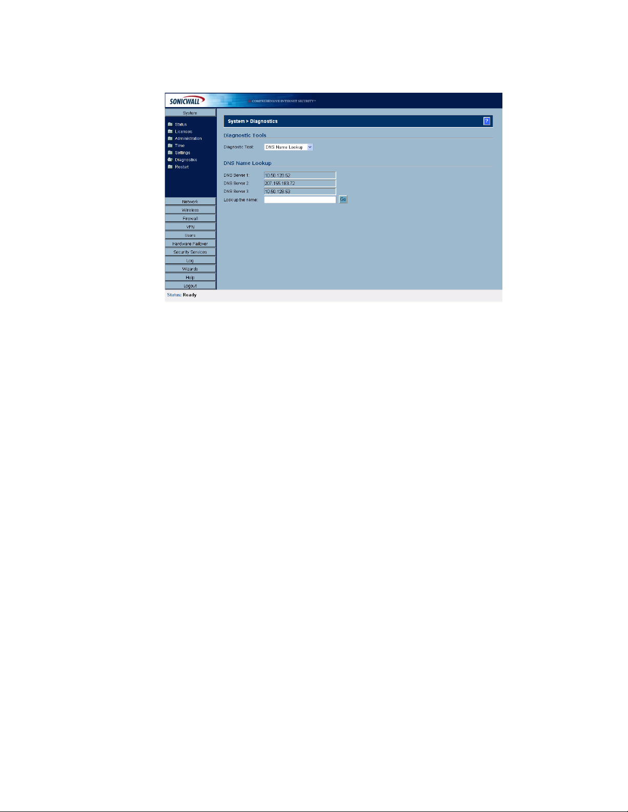
C
HAPTER
8:
Using Diagnostic Tools & Restarting the SonicWALL Security Appliance
Diagnostic Tools
You can choose any of the following diagnostic tools from the Diagnostic Tool menu.
DNS Name Lookup
The SonicWALL security appliance has a DNS lookup tool that returns the IP address of a domain
name. Or, if you type an IP address, it returns the domain name for that address.
1
Type the host name or IP address in the Look up name field. Do not add http to the host name.
2
The SonicWALL security appliance queries the DNS Server and displays the result in the Result
section. It also displays the IP address of the DNS Server used to perform the query.
The DNS Name Lookup section also displays the IP addresses of the DNS Servers configured on the
SonicWALL security appliance. If there is no IP address or IP addresses in the DNS Server fields, you
must configure them on the Network>Settings page.
Find Network Path
Find Network Path indicates if an IP host is located on the WAN, DMZ, LAN, or other zone. This can
diagnose a network configuration problem on the SonicWALL security appliance. For example, if the
SonicWALL security appliance indicates that a computer on the Internet is located on the LAN, then
the network or Intranet settings may be misconfigured. Find Network Path can be used to determine
if a target device is located behind a network router and the Ethernet address of the target device. It
also displays the gateway the device is using and helps isolate configuration problems.
Ping
The Ping test bounces a packet off a machine on the Internet and returns it to the sender. This test
shows if the SonicWALL security appliance is able to contact the remote host. If users on the LAN are
having problems accessing services on the Internet, try pinging the DNS server, or another machine
at the ISP location. If the test is unsuccessful, try pinging devices outside the ISP. If you can ping
devices outside of the ISP, then the problem lies with the ISP connection.
1
Select Ping from the Diagnostic Tool menu.
2
Type the IP address or host name of the target device and click Go.
3
If the test is successful, the SonicWALL security appliance returns a message saying the IP
address is alive and the time to return in milliseconds (ms).
44
SONICWALL SONICOS ENHANCED 2.5 ADMINISTRATOR’S GUIDE
Page 60

Packet Trace
The Packet Trace tool tracks the status of a communications stream as it moves from source to
destination. This is a useful tool to determine if a communications stream is being stopped at the
SonicWALL security appliance, or is lost on the Internet.
To interpret this tool, it is necessary to understand the three-way handshake that occurs for every
TCP connection. The following displays a typical three-way handshake initiated by a host on the
SonicWALL security appliance LAN to a remote host on the WAN.
1
TCP received on LAN [SYN]
From 192.168.168.158 / 1282 (00:a0:4b:05:96:4a)
To 204.71.200.74 / 80 (02:00:cf:58:d3:6a)
System > Diagnostics
The SonicWALL security appliance receives SYN from LAN client.
1
TCP sent on WAN [SYN]
From 207.88.211.116 / 1937 (00:40:10:0c:01:4e)
To 204.71.200.74 / 80 (02:00:cf:58:d3:6a)
The SonicWALL security appliance forwards SYN from LAN client to remote host.
1
TCP received on WAN [SYN,ACK]
From 204.71.200.74 / 80 (02:00:cf:58:d3:6a)
To 207.88.211.116 / 1937 (00:40:10:0c:01:4e)
The SonicWALL security appliance receives SYN,ACK from remote host.
1
TCP sent on LAN [SYN,ACK]
From 204.71.200.74 / 80 (02:00:cf:58:d3:6a)
To 192.168.168.158 / 1282 (00:a0:4b:05:96:4a)
The SonicWALL security appliance forwards SYN,ACK to LAN client.
1
TCP received on LAN [ACK]
From 192.168.168.158 / 1282 (00:a0:4b:05:96:4a)
To 204.71.200.74 / 80 (02:00:cf:58:d3:6a)
Client sends a final ACK, and waits for start of data transfer.
1
TCP sent on WAN [ACK]
From 207.88.211.116 / 1937 (00:40:10:0c:01:4e
SONICWALL SONICOS ENHANCED 2.5 ADMINISTRATOR’S GUIDE
45
Page 61

C
HAPTER
8:
Using Diagnostic Tools & Restarting the SonicWALL Security Appliance
To 204.71.200.74 / 80 (02:00:cf:58:d3:6a)
The SonicWALL security appliance forwards the client ACK to the remote host and waits for the data
transfer to begin.
When using packet traces to isolate network connectivity problems, look for the location where the
three-way handshake is breaking down. This helps to determine if the problem resides with the
SonicWALL security appliance configuration, or if there is a problem on the Internet.
Select Packet Trace from the Diagnostic tool menu.
Tip: Packet Trace requires an IP address. The SonicWALL security appliance DNS Name Lookup
9
tool can be used to find the IP address of a host.
1
Type the IP address of the remote host in the Trace on IP address field, and click Start. You must
type an IP address in the Trace on IP address field; do not type a host name, such as
“www.yahoo.com”. The Trace is off turns from red to green with Trace Active displayed.
2
Contact the remote host using an IP application such as Web, FTP, or Telnet.
3
Click Refresh and the packet trace information is displayed.
4
Click Stop to terminate the packet trace, and Reset to clear the results.
The Captured Packets table displays the packet number and the content of the packet, for instance,
ARP Request send on WAN 42 bytes.
Select a packet in the Captured Packets table to display packet details. Packet details include the
packet number, time, content, source of the IP address, and the IP address destination.
Tech Support Report
The Tech Support Report generates a detailed report of the SonicWALL security appliance
configuration and status, and saves it to the local hard disk. This file can then be e-mailed to
SonicWALL Technical Support to help assist with a problem.
Alert: You must register your SonicWALL security appliance on mySonicWALL.com to receive
S
technical support.
Before e-mailing the Tech Support Report to the SonicWALL Technical Support team, complete a
Tech Support Request Form at <https://www.mysonicwall.com>. After the form is submitted, a unique
case number is returned. Include this case number in all correspondence, as it allows SonicWALL
Technical Support to provide you with better service.
46
In the Tools section, select Tech Support Report from the Select a diagnostic tool menu. Four
Report Options are available in the Tech Support Report section:
• VPN Keys - saves shared secrets, encryption, and authentication keys to the report.
• ARP Cache - saves a table relating IP addresses to the corresponding MAC or physical
addresses.
• DHCP Bindings - saves entries from the SonicWALL DHCP server.
•IKE Info - saves current information about active IKE configurations.
SONICWALL SONICOS ENHANCED 2.5 ADMINISTRATOR’S GUIDE
Page 62

Generating a Tech Support Report
1
Select Tech Support Report from the Choose a diagnostic tool menu.
2
Select the Report Options to be included with your e-mail.
3
Click Save Report to save the file to your system. When you click Save Report, a warning
message is displayed.
4
Click OK to save the file. Attach the report to your Tech Support Request e-mail.
Trace Route
Trace Route is a diagnostic utility to assist in diagnosing and troubleshooting router connections on
the Internet. By using Internet Connect Message Protocol (ICMP) echo packets similar to Ping
packets, Trace Route can test interconnectivity with routers and other hosts that are farther and
farther along the network path until the connection fails or until the remote host responds.
Type the IP address or domain name of the destination host. For example, type yahoo.com and click
Go.
A second window is displayed with each hop to the destination host.
By following the route, you can diagnose where the connection fails between the SonicWALL security
appliance and the destination.
System > Diagnostics
SONICWALL SONICOS ENHANCED 2.5 ADMINISTRATOR’S GUIDE
47
Page 63

C
HAPTER
8:
Using Diagnostic Tools & Restarting the SonicWALL Security Appliance
System > Restart
Click Restart to display the System>Restart page. The SonicWALL security appliance can be
restarted from the Web Management interface. Click Restart SonicWALL and then click Yes to
confirm the restart. The SonicWALL security appliance takes approximately one minute to restart, and
the yellow Test light is lit during the restart.
9
S
Tip: If you made any configuration changes to the SonicWALL security appliance, make sure your
apply them before restarting the SonicWALL security appliance or the changes will not be saved.
Alert: Restarting the SonicWALL security appliance will disconnect all users.
48
SONICWALL SONICOS ENHANCED 2.5 ADMINISTRATOR’S GUIDE
Page 64

P
ART
3
Part 3Network
SONICWALL SONICOS ENHANCED 2.5 ADMINISTRATOR’S GUIDE
49
Page 65

:
50
SONICWALL SONICOS ENHANCED 2.5 ADMINISTRATOR’S GUIDE
Page 66

Chapter 9: Configuring Interfaces
Network > Interfaces
The Network>Interfaces page includes interface objects that are directly linked to physical
interfaces. The SonicOS Enhanced scheme of interface addressing works in conjunction with network
zones and address objects. Physical interface objects include the X0, X1, X3, X4, and X5 ports in the
SonicWALL security appliance.
Network > Interfaces
C
HAPTERW
9
Setup Wizard
The Setup Wizard button accesses the Setup Wizard. The Setup Wizard walks you through
step-by-step the configuration of the SonicWALL security appliance for Internet connectivity.
Cross Reference: For Setup Wizard instructions, see Chapter 48 Configuring Internet Connectivity
Â
using the Setup Wizard.
Physical Interfaces
Physical interfaces must be assigned to a Zone to allow for configuration of Access Rules to govern
inbound and outbound traffic. Security zones are bound to each physical interface where it acts as a
conduit for inbound and outbound traffic. If there is no interface, traffic cannot access the zone or exit
the zone.
Cross Reference: For more information on zone, see Chapter 11 Configuring Zones.
Â
The first two interfaces, X0(LAN) and X1(WAN) are fixed interfaces, permanently bound to the
Trusted and Untrusted Zone types. The remaining Interfaces can be configured and bound to any
Zone type, depending on your SonicWALL security appliance:
• SonicWALL PRO 3060/PRO 4060/PRO5060 security appliances include four user-definable
interfaces, X2, X3, X4, and X5.
• SonicWALL PRO 2040 security appliance includes two user-definable interfaces, X2 and X3.
• SonicWALL TZ 170 security includes one user definable interface, OPT.
Note: The Untrusted Zone type can only have two members, one of which is the fixed interface, X1.
SONICWALL SONICOS ENHANCED 2.5 ADMINISTRATOR’S GUIDE
51
Page 67

C
HAPTER
9:
Configuring Interfaces
SonicOS Enhanced Secure Objects
The SonicOS Enhanced scheme of interface addressing works in conjunction with network zones and
address objects. This structure is based on secure objects, which are utilized by rules and policies
within SonicOS Enhanced. Physical interface objects include the X0, X1, X3, X4, and X5 ports in the
SonicWALL security appliance linked to the LAN, WAN, DMZ, WLAN, and Custom zones. Address
objects comprise a host, a network, a range of addresses, or a MAC address.
Secured objects include interface objects that are directly linked to physical interfaces and managed
in the Network>Interfaces page. Address objects that are defined in the Network>Objects page.
Service and Scheduling objects are defined in the Firewall section of the SonicWALL security
appliance Management Interface, and User objects are defined in the Users section of the
SonicWALL security appliance Management Interface.
Zones are the hierarchical apex of SonicOS Enhanced’s secure objects architecture. SonicOS
Enhanced includes pre-defined zones as well as allow you to define your own zones. Predefined
zones include LAN, DMZ, WAN, WLAN, and Custom. Zones can include multiple interfaces, however,
the WAN Zone is restricted to a total of two interfaces. Within the WAN zone, either one or both WAN
interfaces can be actively passing traffic depending on the WAN Failover and Load-Balancing
configuration on the Network>WAN Failover & LB page.
Cross Reference: For more information on WAN Failover and Load Balancing on the SonicWALL
Â
security appliance, see Chapter 10 Setting Up Network WAN Failover and Load Balancing.
At the zone configuration level, the Allow Interface Trust setting for zones automates the processes
involved in creating a permissive intra-zone Access Rule. It creates a comprehensive Address Object
for the entire zone and a inclusively permissive Access Rule from zone address to zone addresses.
Transparent Mode
Transparent Mode in SonicOS Enhanced does not employ the concept of zones. Instead Transparent
mode uses interfaces as the top level of the management hierarchy. Transparent Mode supports
unique addressing and interface routing.
Alert: Zones are not supported in Transparent Mode.
S
Interface Settings
52
The Interface Settings table lists the following information for each interface:
SONICWALL SONICOS ENHANCED 2.5 ADMINISTRATOR’S GUIDE
Page 68

•Name - listed as X0, X1, X2, X3, X4, and X5 or LAN, WAN, WLAN, Custom, or OPT/DMZ
depending on your SonicWALL security appliance model.
•Zone - LAN, DMZ/OPT and WAN are listed by default. As zones are configured, the names are
listed in this column.
•IP Address - IP address assigned to the interface.
• Subnet Mask - the network mask assigned to the subnet.
• IP Assignment - you can select from DHCP or Static for LAN. For WAN, you can select from
DHCP, Static, PPPoE, PPTP, or L2TP.
•Status - the link status and speed.
• Comment - any user-defined comments.
• Configure - click the Notepad icon to display the Edit Interface window, which allows you to
configure the settings for the specified interface.
Inteface Traffic Statistics
The Interface Traffic Statistics table lists received and transmitted information for all configured
interfaces.
Network > Interfaces
The following information is displayed for all SonicWALL security appliance interfaces:
• Rx Unicast Packets - indicates the number of two-way, point-to-point communications received
by the interface.
• Rx Broadcast Packets - indicates the number of multipoint communications received by the
interface.
•RX Bytes - indicates the volume of data, in bytes, received by the interface.
• Tx Unicast Packets - indicates the number of two-way, point-to-point communications received
by the interface.
• Tx Broadcast Bytes - indicates the number of mutlipoint communications received by the
interface.
•Tx Bytes - indicates the volume of data, in bytes, transmitted by the interface.
To clear the current statistics, click the Clear Statistics button at the top right of the
Network>Interfaces page.
Alert: You cannot change the Zones in the Edit Interface window for the X0 (Default LAN) and X1
S
(Default WAN) interfaces.
Configuring the LAN/DMZ/Custom Interface (Static)
Static means you assign a fixed IP address to the interface.
SONICWALL SONICOS ENHANCED 2.5 ADMINISTRATOR’S GUIDE
53
Page 69

C
HAPTER
9:
Configuring Interfaces
1
Click on the Notepad icon in the Configure column for Unassigned Interface you want to
configure. The Edit Interface window is displayed.
2
Select the LAN interface. If you want to create a new zone for the interface, select Create a new
zone. The Add Zone window is displayed. See Chapter 11 for instructions on adding a zone.
3
Select Static from the IP Assignment menu.
4
Enter the IP address and subnet mask of the Zone in the IP Address and Subnet Mask fields.
5
Enter any optional comment text in the Comment field. This text is displayed in the Comment
column of the Interface table.
6
If you want to enable remote management of the SonicWALL security appliance from this
interface, select the supported management protocol(s): HTTP, HTTPS, Ping, and/or SNMP.
7
If you want to allow selected users with limited management rights, select HTTP and/or HTTPS in
User Login.
8
Click OK.
54
Note: The administrator password is required to regenerate encryption keys after changing the
SonicWALL security appliance’s address.
SONICWALL SONICOS ENHANCED 2.5 ADMINISTRATOR’S GUIDE
Page 70

Configuring Advanced Settings for the Interface
If you need to force an Ethernet speed, duplex and/or MAC address, click the Advanced tab.
Network > Interfaces
The Ethernet Settings section allows you to manage the Ethernet settings of links connected to the
SonicWALL. Auto Negotiate is selected by default as the Link Speed because the Ethernet links
automatically negotiate the speed and duplex mode of the Ethernet connection. If you want to specify
the forced Ethernet speed and duplex, select one of the following options from the Link Speed menu:
• 1000 Mbps - Full Duplex
• 100 Mbps - Full Duplex
• 100 Mbps - Half Duplex
• 10 Mbps - Full Duplex
• 10 Mbps - Half Duplex
You can choose to override the Default MAC Address for the Interface by selecting Override
Default MAC Address and entering the MAC Address in the field.
Check Enable Multicast Support to allow multicast reception on this interface.
Alert: If you select a specific Ethernet speed and duplex, you must force the connection speed and
S
duplex from the Ethernet card to the SonicWALL security appliance as well.
Configuring the LAN/DMZ/Custom Interface
(Transparent Mode)
Transparent Mode enables the SonicWALL security appliance to bridge the WAN subnet onto an
internal interface.
1
Click on the Notepad icon in the Configure column for Unassigned Interface you want to
configure. The Edit Interface window is displayed.
2
Select the LAN interface. If you want to create a new zone for the interface, select Create a new
zone. The Add Zone window is displayed. See Chapter 11 for instructions on adding a zone.
SONICWALL SONICOS ENHANCED 2.5 ADMINISTRATOR’S GUIDE
55
Page 71

C
HAPTER
9:
Configuring Interfaces
3
Select Transparent Mode from the IP Assignment menu.
4
Select the address object from the Transparent Range menu. See Chapter 13 for more
information.
5
Enter any optional comment text in the Comment field. This text is displayed in the Comment
column of the Interface table.
6
If you want to enable remote management of the SonicWALL security appliance from this
interface, select the supported management protocol(s): HTTP, HTTPS, Ping, and/or SNMP.
7
If you want to allow selected users with limited management rights, select HTTP and/or HTTPS in
User Login.
8
Click OK.
Note: The administrator password is required to regenerate encryption keys after changing the
SonicWALL security appliance’s address.
Configuring Advanced Settings for the Interface
If you need to force an Ethernet speed, duplex and/or MAC address, click the Advanced tab. The
Ethernet Settings section allows you to manage the Ethernet settings of links connected to the
SonicWALL. Auto Negotiate is selected by default as the Link Speed because the Ethernet links
automatically negotiate the speed and duplex mode of the Ethernet connection. If you want to specify
the forced Ethernet speed and duplex, select one of the following options from the Link Speed menu:
• 1000 Mbps - Full Duplex
• 100 Mbps - Full Duplex
• 100 Mbps - Half Duplex
• 10 Mbps - Full Duplex
• 10 Mbps - Half Duplex
You can choose to override the Default MAC Address for the Interface by selecting Override
Default MAC Address and entering the MAC Address in the field.
Check Enable Multicast Support to allow multicast reception on this interface.
Alert: If you select a specific Ethernet speed and duplex, you must force the connection speed and
S
duplex from the Ethernet card to the SonicWALL security appliance as well.
56
SONICWALL SONICOS ENHANCED 2.5 ADMINISTRATOR’S GUIDE
Page 72

Configuring the WLAN Interface
Static means you assign a fixed IP address to the interface.
1
Click on the Notepad icon in the Configure column for Unassigned Interface you want to
configure. The Edit Interface window is displayed.
2
Select the WLAN interface. If you want to create a new zone for the interface, select Create a new
zone. The Add Zone window is displayed. See Chapter 11 for instructions on adding a zone.
3
Enter the IP address and subnet mask of the Zone in the IP Address and Subnet Mask fields.
4
Enter any optional comment text in the Comment field. This text is displayed in the Comment
column of the Interface table.
5
If you want to enable remote management of the SonicWALL security appliance from this
interface, select the supported management protocol(s): HTTP, HTTPS, Ping, and/or SNMP.
6
If you want to allow selected users with limited management rights, select HTTP and/or HTTPS in
User Login.
7
Click OK.
Network > Interfaces
Note: The administrator password is required to regenerate encryption keys after changing the
SonicWALL security appliance’s address.
Configuring Advanced Settings for the Interface
If you need to force an Ethernet speed, duplex and/or MAC address, click the Advanced tab. The
Ethernet Settings section allows you to manage the Ethernet settings of links connected to the
SonicWALL. Auto Negotiate is selected by default as the Link Speed because the Ethernet links
automatically negotiate the speed and duplex mode of the Ethernet connection. If you want to specify
the forced Ethernet speed and duplex, select one of the following options from the Link Speed menu:
• 1000 Mbps - Full Duplex
• 100 Mbps - Full Duplex
• 100 Mbps - Half Duplex
• 10 Mbps - Full Duplex
• 10 Mbps - Half Duplex
You can choose to override the Default MAC Address for the Interface by selecting Override
Default MAC Address and entering the MAC Address in the field.
Check Enable Multicast Support to allow multicast reception on this interface.
S
Alert: If you select a specific Ethernet speed and duplex, you must force the connection speed and
duplex from the Ethernet card to the SonicWALL as well.
Configuring the WAN Interface
Configuring the WAN interface enables Internet connect connectivity. You can configure up to two
WAN interfaces on the SonicWALL security appliance.
1
Click on the Notepad icon in the Configure column for the WAN or Unassigned Interface you
want to configure. The Edit Interface window is displayed.
SONICWALL SONICOS ENHANCED 2.5 ADMINISTRATOR’S GUIDE
57
Page 73
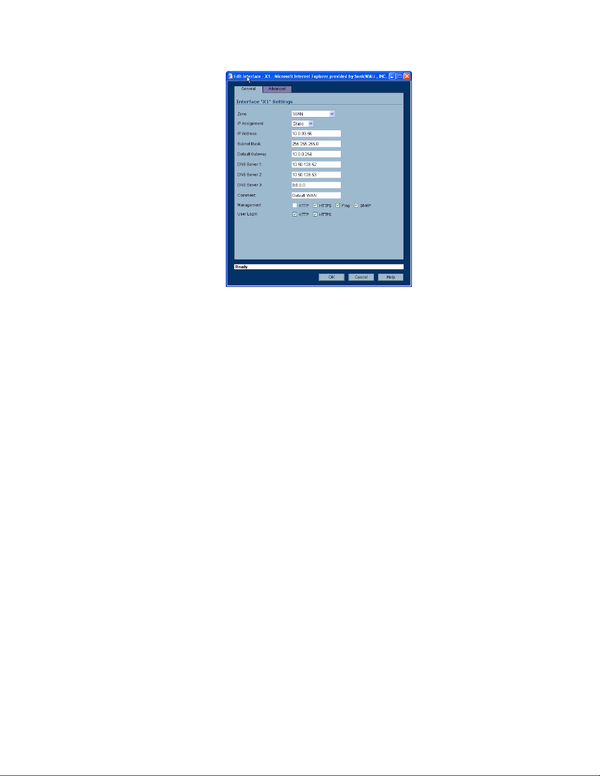
C
HAPTER
9:
Configuring Interfaces
2
If you’re configuring an Unassigned Interface, select WAN from the Zone menu. If you selected
the Default WAN Interface, WAN is already selected in the Zone menu.
3
Select one of the following WAN Network Addressing Mode from the IP Assignment menu.
Depending on the option you choose from the IP Assignment menu, complete the corresponding
fields that are displayed after selecting the option.
Static - configures the SonicWALL for a network that uses static IP addresses.
DHCP - configures the SonicWALL to request IP settings from a DHCP server on the Internet.
NAT with DHCP Client is a typical network addressing mode for cable and DSL customers.
PPPoE - uses Point to Point Protocol over Ethernet (PPPoE) to connect to the Internet. If desktop
software and a username and password is required by your ISP, select NAT with PPPoE. This
protocol is typically found when using a DSL modem.
PPTP - uses PPTP (Point to Point Tunneling Protocol) to connect to a remote server. It supports
older Microsoft Windows implementations requiring tunneling connectivity.
L2TP - uses IPSec to connect a L2TP server and encrypts all data transmitted from the client to
the server. However, it does not encrypt network traffic to other destinations. L2TP (Layer 2
Tunneling Protocol) is supported by Windows 2000 and Windows XP. If you are running other
versions of Windows, you must use PPTP as your tunneling protocol.
4
After completing the WAN configuration for your Network Addressing Mode, click OK
Static
DHCP
58
IP Address
Subnet Mask
Default Gateway
DNS Server 1
DNS Server 2
DNS Server 3
Comment
Management
User Login
Host Name
SONICWALL SONICOS ENHANCED 2.5 ADMINISTRATOR’S GUIDE
Page 74

PPPoE
Network > Interfaces
Comment
Management
User Login
Renew
Release
Refresh
User Name
User Password
Comment
Management
User Login
Inactivity Disconnect (minutes)
Obtain IP Address Automatically
Specify IP Address
Obtain DNS Server Address Automatically
Specify DNS Server
PPTP
User Name
User Password
PPTP Server IP Address
PPTP (Client) Host Name
Comment
Management
User Login
Inactivity Disconnect (minutes)
PPTP IP Assignment
DHCP
Renew
Release
Refresh
Static
IP Address
Subnet Mask
Gateway (Router) Address
L2TP
User Name
User Password
L2TP Server IP Address
L2TP (Client) Host Name
Comment
SONICWALL SONICOS ENHANCED 2.5 ADMINISTRATOR’S GUIDE
59
Page 75
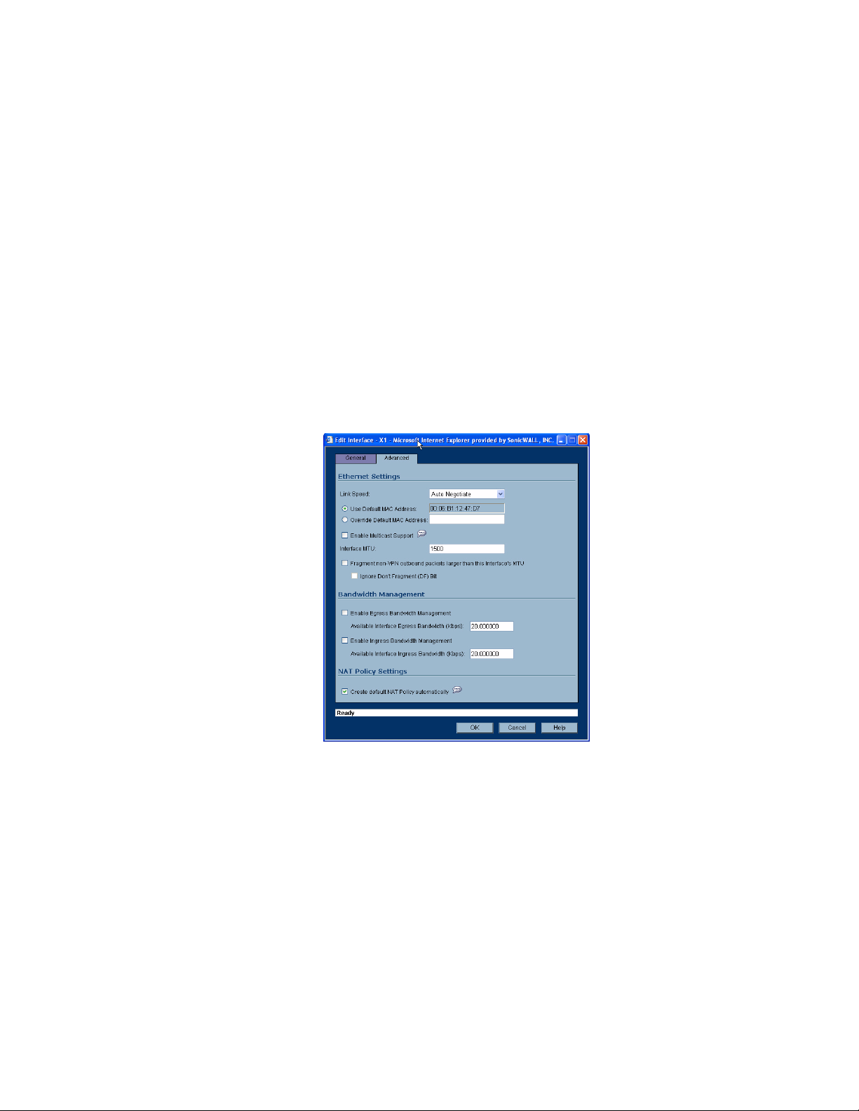
C
HAPTER
9:
Configuring Interfaces
Management
User Login
Inactivity Disconnect (minutes)
L2TP IP Assignment
DHCP
Renew
Release
Refresh
Static
IP Address
Subnet Mask
Gateway (Router) Address
Configuring the Advanced Settings for the WAN Interface
The Advanced tab includes settings for forcing an Ethernet speed and duplex, overriding the Default
MAC Address, setting up bandwidth management, and creating a default NAT policy automatically.
Ethernet Settings
If you need to force an Ethernet speed, duplex and/or MAC address, click the Advanced tab. The
Ethernet Settings section allows you to manage the Ethernet settings of links connected to the
SonicWALL. Auto Negotiate is selected by default as the Link Speed because the Ethernet links
automatically negotiate the speed and duplex mode of the Ethernet connection. If you want to specify
the forced Ethernet speed and duplex, select one of the following options from the Link Speed menu:
• 100 Mbps - Full Duplex
• 100 Mbps - Half Duplex
• 10 Mbps - Full Duplex
• 10 Mbps - Half Duplex
You can choose to override the Default MAC Address for the Interface by selecting Override
Default MAC Address and entering the MAC Address in the field.
60
SONICWALL SONICOS ENHANCED 2.5 ADMINISTRATOR’S GUIDE
Page 76

Check Enable Multicast Support to allow multicast reception on this interface.
Alert: If you select a specific Ethernet speed and duplex, you must force the connection speed and
S
duplex from the Ethernet card to the SonicWALL as well.
You can also specify any of these additional Ethernet Settings:
• Interface MTU - Specifies the largest packet size that the interface can forward without
fragmenting the packet.
• Fragment non-VPN outbound packets larger than this Interface’s MTU - Specifies all nonVPN outbound packets larger than this Interface’s MTU be fragmented. Specifying the
fragmenting of VPN outbound packets is set in the VPN>Advanced page.
• Ignore Don’t Fragment (DF) Bit - Overrides DF bits in packets.
Bandwidth Management
SonicOS Enhanced can apply bandwidth management to both egress and ingress traffic on the WAN
interface. Class Based Queuing (CBQ) provides guaranteed and maximum bandwidth Quality of
Service (QoS) for the SonicWALL security appliance. Every packet destined to the WAN interface is
queued in the corresponding priority queue. The scheduler then dequeues the packets and transmits
it on the link depending on the guaranteed bandwidth for the flow and the available link bandwidth.
Network > Interfaces
The Bandwidth Management section allows you to specify the available outbound bandwidth for this
interface in Kbps.
• Enable Egress Bandwidth Management - Enables outbound bandwidth management.
Available Interface Egress Bandwidth (Kbps) - Specifies the available bandwidth for this
interface in Kbps.
• Enable Ingress Bandwidth Management - Enables inbound bandwidth management.
Available Interface Ingress Bandwidth (Kbps) - Specifies the available bandwidth for this
interface in Kbps.
NAT Policy Settings
Selecting Create default NAT Policy automatically translates the Source Address of packets from
the Default LAN (Primary LAN) to your new WAN Interface.
Cross Reference: For more information on NAT Policies, see Chapter 15 Configuring Network NAT
Â
Policies.
SONICWALL SONICOS ENHANCED 2.5 ADMINISTRATOR’S GUIDE
61
Page 77

C
HAPTER
9:
Configuring Interfaces
62
SONICWALL SONICOS ENHANCED 2.5 ADMINISTRATOR’S GUIDE
Page 78

Chapter 10: Setting Up WAN Failover and
Load Balancing
Network > WAN Failover & LB
Network > WAN Failover & LB
C
HAPTER
10
WAN Failover and Load Balancing allows you to designate one of the user-assigned interfaces as a
Secondary or backup WAN port. The Secondary WAN port can be used in a simple active/passive
setup, where traffic is only routed through the Secondary WAN port if the Primary WAN port is down
and/or unavailable. In this chapter, this feature is referred to as basic failover. This allows the
SonicWALL security appliance to maintain a persistent connection for WAN port traffic by failing over
to the secondary WAN port. It can also be used in a more dynamic active/active setup, where the
administrator can choose a method of dividing outbound traffic flows between the Primary fixed WAN
port and the user-assigned Secondary WAN port. This latter feature is referred to as load balancing.
WAN Failover Caveats
• WAN Failover and Load-Balancing applies to outbound-initiated traffic only; it cannot be used to
perform inbound load-balancing functions, such as what a content switching or load-balancing
appliance provides.
• Make sure that the SonicWALL security appliance has the proper NAT policies for the Secondary
WAN interface an incorrect or missing NAT Policy for the Secondary WAN port is the most
common problem seen when configuring WAN Failover & Load-Balancing.
• The Primary and Secondary WAN ports cannot be on the same IP subnet; each WAN connection
must be on unique IP subnets in order to work properly
SONICWALL SONICOS ENHANCED 2.5 ADMINISTRATOR’S GUIDE
63
Page 79

C
HAPTER
10:
Setting Up WAN Failover and Load Balancing
Setting Up WAN Failover and Load Balancing
The following are the steps to configuring WAN Failover and Load Balancing on the SonicWALL
security appliance:
1
Configuring an interface as a Secondary WAN port
2
Creating a NAT Policy for the Secondary WAN port
3
Activating WAN Failover/Load-Balancing
4
Choosing a WAN Failover/Load-Balancing method
5
Setting Up Probe Monitoring
Configuring an Interface as a Secondary WAN Port
On Network > Interfaces page, configure the chosen port to be in WAN zone, and enter in the correct
address settings provided by the Secondary ISP. In the example, the SonicWALL security appliance
is acquiring its secondary WAN address dynamically from ISP #2, using DHCP. Any interface added
to the WAN zone by default creates a NAT Policy allowing internal LAN subnets to NAT out this
Secondary WAN interface.
Creating a NAT Policy for the Secondary WAN Port
You need to create a NAT policy on your SonicWALL for WAN Failover. Follow these steps to create
a NAT policy on your SonicWALL using the X4 interface (PRO 3060/4060/PRO5060) or OPT
interface (TZ 170):
1
Select Network>NAT Policies.
2
Click Add. The Add NAT Policy window is displayed.
3
Select Any from the Original Source menu.
4
Select X4 IP (PRO 3060/4060/5060) or OPT IP (TZ 170) from the Translated Source menu.
5
Select Any from the Original Destination menu.
6
Select Original from the Translated Destination menu.
7
Select Any from the Original Service menu.
8
Select Original from the Translated Service menu.
9
Select X0 from the Inbound Interface menu.
10
Select X4 (PRO 3060/4060/PRO5060) or OPT interface (TZ 170) from the Outbound Interface
menu.
11
Make sure the Enable setting is checked.
12
Click OK.
64
SONICWALL SONICOS ENHANCED 2.5 ADMINISTRATOR’S GUIDE
Page 80

Activating WAN Failover and Load Balancing
To configure the SonicWALL for WAN failover and load balancing, follow the steps below:
1
On Network > WAN Failover & LB page, select Enable Load Balancing.
2
From the Secondary WAN Interface menu, select your secondary WAN interface.
3
Enter a number between 5 and 300, in the Check Interface Every _ Seconds field. You can use
the default value of 5 seconds
4
In the Deactivate Interface after _ missed intervals, enter a number between 1 and 10. You can
use the default value of 3. If the default value is used, then the interface is considered inactive
after 3 successive attempts at 5 seconds each.
5
Enter a number between 1 and 10 in the Reactivate Interface after _ successful intervals. You
can use the default value of 3. If the default value is used, then the interface is considered active
after 3 successive attempts at 5 seconds each.
6
Click Apply.
Network > WAN Failover & LB
Choosing an Outbound Load Balancing Method
You need to choose a load balancing method. By default, the SonicWALL will select Basic Active/
Passive Failover as the method, but there are four load balancing methods available:
• Basic Active/Passive Failover: When this setting is selected, the SonicWALL security appliance
only sends traffic through the Secondary WAN interface if the Primary WAN interface has been
marked inactive. The SonicWALL security appliance is set to use this as the default load balancing
method. If the Primary WAN fails, then the SonicWALL security appliance reverts to this method
instead of the ones described below. This mode will automatically return back to using the Primary
WAN interface once it has been restored (preempt mode). This item has an associated Preempt
and fail back to Primary WAN when possible checkbox. When this checkbox is selected, the
SonicWALL security appliance switches back to sending its traffic across the Primary WAN
interface when it resumes responding to the SonicWALL security appliance’s checks (the WAN’s
physical link is restored, or the logical probe targets on the WAN port resume responding).
SONICWALL SONICOS ENHANCED 2.5 ADMINISTRATOR’S GUIDE
65
Page 81

C
HAPTER
10:
Setting Up WAN Failover and Load Balancing
• Per Destination Round-Robin: When this setting is selected, the SonicWALL security appliance
load-balances outgoing traffic on a per-destination basis. This is a simple load balancing method
and, though not very granular, allows you to utilize both links in a basic fashion (instead of the
method above, which does not utilize the capability of the Secondary WAN until the Primary WAN
has failed). The SonicWALL security appliance needs to examine outbound flows for uniqueness
in source IP and destination IP and make the determination as to which interface to send the traffic
out of and accept it back on. Please note this feature will be overridden by specific static route
entries.
• Spillover-Based: When this settings is selected, the user can specify when the SonicWALL
security appliance starts sending traffic through the Secondary WAN interface. This method allows
you to control when and if the Secondary interface is used. This method is used if you do not want
outbound traffic sent across the Secondary WAN unless the Primary WAN is overloaded. The
SonicWALL security appliance has a non-Management Interface exposed hold timer set to 20
seconds – if the sustained outbound traffic across the Primary WAN interface exceeds the
administrator defined Kbps, then the SonicWALL security appliance spills outbound traffic to the
Secondary WAN interface (on a per-destination basis). The user entry box should not have a
default entry and be left empty for the user. Please note this feature will be overridden by specific
static route entries.
• Percentage-Based: When this setting is selected, you can specify the percentages of traffic sent
through the Primary WAN and Secondary WAN interfaces. This method allows you to actively
utilize both Primary and Secondary WAN interfaces. Only one entry box is required (percentage
for Primary WAN), as the SonicWALL will auto-populate a non-user-editable entry box with the
remaining percentage assigned to the Secondary WAN interface. Please note this feature will be
overridden by specific static route entries.
Enabling WAN Probe Monitoring
If Probe Monitoring is not activated, the SonicWALL security appliance performs physical monitoring
only on the Primary and Secondary WAN interfaces, meaning it only marks a WAN interface as failed
if the interface is disconnected or stops receiving an Ethernet-layer signal. This is not an assured
means of link monitoring, because it does not address most failure scenarios, i.e. routing issues with
your ISP, or an upstream router that is no longer passing traffic. For example, if the WAN interface is
connected to a hub or switch, and the router providing the connection to the ISP (also connected to
this hub or switch) were to fail, the SonicWALL will continue to believe the WAN link is usable,
because the connection to the hub or switch is good.
Selecting Enabling Probe Monitoring on Network>WAN Failover & LB page allows the
SonicWALL security appliance to perform logical checks of upstream targets to ensure that the line is
indeed usable, eliminating this potential problem, as well as continue to do physical monitoring. If
Probe Monitoring is activated and the settings are left blank, the SonicWALL performs an ICMP ping
probe of both WAN ports’ default gateways. Unfortunately, this is also not an assured means of link
monitoring, because service interruption may be occurring farther upstream. If your ISP is
experiencing problems in its routing infrastructure, a successful ICMP ping of their router causes the
SonicWALL security appliance to believe the line is usable, when in fact it may not be able to pass
traffic to and from the public Internet at all.
To perform reliable link monitoring, you can choose ICMP or TCP as monitoring method, and can
specify up to two targets for each WAN port. TCP is preferred because many devices on the public
Internet now actively drop or block ICMP requests. If you specify two targets for each WAN interface,
you can logically link the two probe targets such that if either one fails the line will go down, or that
both must fail for the line to be considered down. Using the latter method, you can configure a sort of
‘deep check’ to see if the line is truly usable – for instance, you could set first probe target of your
ISP’s router interface using ICMP (assuming they allow this), and then do a secondary probe target of
a DNS server on the public Internet using TCP Port 53. With this method, if the ICMP probe of the
ISP’s router fails but the farther upstream continues to respond, the SonicWALL security appliance
assumes the link is usable and continue to send traffic across it.
66
SONICWALL SONICOS ENHANCED 2.5 ADMINISTRATOR’S GUIDE
Page 82

Configuring WAN Probe Monitoring
To configure WAN probe monitoring, follow these steps:
1
On the Network > WAN Failover & LB page, check the Enable Probe Monitoring box, and click
on the Configure button. The Configure WAN Probe Monitoring window is displayed.
2
In the Primary WAN Probe Settings menu, select one of the following options:
Probe succeeds when either Main Target or Alternate Target responds.
Probe succeeds when both Main Target and Alternative Target respond.
Probe succeeds when Main Target responds.
Succeeds Always (no probing).
3
Select Ping (ICMP) or TCP from the Probe Target menu.
4
Enter the IP address of the target device in the IP Address field.
5
Enter a port number in the Port field.
6
In the Secondary WAN Probe Settings menu, select one of the following options:
Probe succeeds when either Main Target or Alternate Target responds.
Probe succeeds when both Main Target and Alternative Target respond.
Probe succeeds when Main Target responds.
Succeeds Always (no probing).
7
Select Ping (ICMP) or TCP from the Probe Target menu.
8
Enter the IP address of the target device in the IP Address field.
9
Enter a port number in the Port field.
10
Click OK.
Network > WAN Failover & LB
S
SONICWALL SONICOS ENHANCED 2.5 ADMINISTRATOR’S GUIDE
Alert: Before you begin, be sure you have configured a user-defined interface to mirror the WAN port
settings.
Note: If the Probe Target is unable to contact the target device, the interface is deactivated and traffic
is no longer sent to the primary WAN.
67
Page 83

C
HAPTER
10:
Setting Up WAN Failover and Load Balancing
WAN Load Balancing Statistics
The WAN Load Balancing Statistics table displays the following WAN Interface statistics for the
SonicWALL:
•Link Status
• Load Balancing State
• Probe Monitoring
• New Connections
• Total Connections
• Rx Unicast Packets
•Rx Bytes
• Tx Unicast Packets
•Tx Bytes
• Tx Current Percentage
• Tx Current Throughput (KB/s)
Click the Clear Statistic button on the top right of the Network>WAN Failover & Load Balancing
page to clear information from the WAN Load Balancing Statistics table.
68
SONICWALL SONICOS ENHANCED 2.5 ADMINISTRATOR’S GUIDE
Page 84

Network > Zones
A Zone is a logical grouping of one or more interfaces designed to make management, such as the
definition and application of Access Rules, a simpler and more intuitive process than following strict
physical interface scheme. Zone-based security is a powerful and flexible method of managing both
internal and external network segments, allowing the administrator to separate and protect critical
internal network resources from unapproved access or attack.
Network > Zones
C
HAPTER
11
Chapter 11: Configuring Zones
A network security zone is simply a logical method of grouping one or more interfaces with friendly,
user-configurable names, and applying security rules as traffic passes from one zone to another
zone. Security zones provide an additional, more flexible, layer of security for the firewall. With the
zone-based security, the administrator can group similar interfaces and apply the same policies to
them, instead of having to write the same policy for each interface.
Cross Reference: For more information on configuring interfaces, see Chapter 9 Configuring
Â
Interfaces.
SonicOS Enhanced zones allows you to apply security policies to the inside of the network. This
allows the administrator to do this by organizing network resources to different zones, and allowing or
restricting traffic between those zones. This way, access to critical internal resources such as payroll
servers or engineering code servers can be strictly controlled.
Zones also allow full exposure of the NAT table to allow the administrator control over the traffic
across the interfaces by controlling the source and destination addresses as traffic crosses from one
zone to another. This means that NAT can be applied internally, or across VPN tunnels, which is a
feature that users have long requested. SonicWALL security appliances can also drive VPN traffic
through the NAT policy and zone policy, since VPNs are now logically grouped into their own VPN
zone.
How Zones Work
An easy way to visualize how security zones work is to imagine a large new building, with several
rooms inside the building, and a group of new employees that do not know their way around the
building. This building has one or more exits, which can be thought of as the WAN interfaces. The
rooms within the building have one or more doors, which can be thought of as interfaces. These
rooms can be thought of as zones inside each room are a number of people. The people are
categorized and assigned to separate rooms within the building. People in each room going to
another room or leaving the building, must talk to a doorperson on the way out of each room. This
SONICWALL SONICOS ENHANCED 2.5 ADMINISTRATOR’S GUIDE
69
Page 85

C
HAPTER
11:
Configuring Zones
doorperson is the inter-zone/intra-zone security policy, and the doorperson’s job to consult a list and
make sure that the person is allowed to go to the other room, or to leave the building. If the person is
allowed (i.e. the security policy lets them), they can leave the room via the door (the interface).
Upon entering the hallway, the person needs to consult with the hallway monitor to find out where the
room is, or where the door out of the building is located. This hallway monitor provides the routing
process because the monitor knows where all the rooms are located, and how to get in and out of the
building. The monitor also knows the addresses of any of the remote offices, which can be considered
the VPNs. If the building has more than one entrance/exit (WAN interfaces), the hallway monitor can
direct people to use the secondary entrance/exit, depending upon how they’ve been told to do so (i.e.
only in an emergency, or to distribute the traffic in and out of the entrance/exits). This function can be
thought of as WAN load balancing.
There are times that the rooms inside the building have more than one door, and times when there
are groups of people in the room who are not familiar with one another. In this example, one group of
people uses only one door, and another group uses the other door, even though groups are all in the
same room. Because they also don’t recognize each other, in order to speak with someone in another
group, the users must ask the doorperson (the security policy) to point out which person in the other
group is the one with whom they wish to speak. The doorperson has the option to not let one group of
people talk to the other groups in the room. This is an example of when zones have more than one
interface bound to them, and when intra-zone traffic is not allowed.
Sometimes, people will wish to visit remote offices, and people may arrive from remote offices to visit
people in specific rooms in the building. These are the VPN tunnels. The hallway and doorway
monitors check to see if this is allowed or not, and allow traffic through. The doorperson can also elect
to force people to put on a costume before traveling to another room, or to exit, or to another remote
office. This hides the true identity of the person, masquerading the person as someone else. This
process can be thought of as the NAT policy.
Predefined Zones
The predefined zones on your the SonicWALL security appliance depend on the device. The following
are all the SonicWALL security appliance’s predefined security zones:
The pre-defined security zones on the SonicWALL security appliance are not modifiable and are
defined as follows:
•WAN: This zone can consist of either one or two interfaces. If you’re using the security appliance’s
WAN failover capability, you need to add the second Internet interface to the WAN zone.
•LAN: This zone can consist of one to five interfaces, depending on your network design. Even
though each interface will have a different network subnet attached to it, when grouped together
they can be managed as a single entity.
70
SONICWALL SONICOS ENHANCED 2.5 ADMINISTRATOR’S GUIDE
Page 86

•DMZ: This zone is normally used for publicly accessible servers. This zone can consist of one to
four interfaces, depending on you network design.
• VPN: This virtual zone is used for simplifying secure, remote connectivity. It is the only zone that
does not have an assigned physical interface.
•WLAN: This zone provides support to SonicWALL SonicPoints.
• MULTICAST: This zone provides support for IP multicasting, which is a method for sending IN
packets from a single source simultaneously to multiple hosts.
Note: Even though you may group interfaces together into one security zone, this does not preclude
you from addressing a single interface within the Zone.
Security Types
Each zone has a security type. The security type defines the of trust given to that zone. There are five
security types:
• Trusted: Trusted is a security type that provides the highest level of trust--meaning that the least
amount of scrutiny is applied to traffic coming from trusted zones. Trusted security can be thought
of as being on the LAN (protected) side of the security appliance. The LAN zone is always Trusted.
• Encrypted: Encrypted is a security type used exclusively by the VPN Zone. All traffic to and from
an Encrypted zone is encrypted.
Network > Zones
• Wireless: Wireless is a security type applied to the WLAN zone or any zone where the only
interface to the network consists of SonicWALL SonicPoint devices. You typically use WiFiSec to
secure traffic in a Wireless zone. The Wireless security type is designed specifically for use with
SonicPoint devices. Placing an interface in a Wireless Zone activates SDP (SonicWALL Discovery
Protocol) and SSPP (SonicWALL Simple Provisioning Protocol) on that interface for automatic
discovery and provisioning of SonicPoint devices. Only traffic that passes through a SonicPoint is
allowed through a Wireless zone; all other traffic is dropped.
• Public: A Public security type offers a higher level of trust than an Untrusted zone, but a lower
level of trust than a Trusted zone. Public zones can be thought of as being a secure area between
the LAN (protected) side of the security appliance and the WAN (unprotected) side. The DMZ, for
example, is a Public zone because traffic flows from it to both the LAN and the WAN, but it will only
have default access to the WAN, not the LAN.
• Untrusted: The Untrusted security type represents the lowest level of trust. It is used by both the
WAN and the virtual Multicast zone. An Untrusted zone can be thought of as being on the WAN
(unprotected) side of the security appliance.By default, traffic from Untrusted zones is not
permitted to enter any other zone type without explicit rules, but traffic from every other zone type
is permitted to Untrusted zones.
Allow Interface Trust
The Allow Interface Trust setting in the Add Zone window automates the creation of Access Rules
to allow traffic to flow between the Interfaces of a zone instance. For example, if the LAN Zone has
interfaces X0, X3, and X5 assigned to it, checking Allow Interface Trust on the LAN Zone creates
the necessary Access Rules to allow hosts on these Interfaces to communicate with each other.
Enabling SonicWALL Security Services on Zones
You can enable SonicWALL Security Services for traffic across zones. For example, you can enable
SonicWALL Intrusion Prevention Service for incoming and outgoing traffic on the WLAN zone to add
more security for internal network traffic. You can enable the following SonicWALL Security Services
on zones:
SONICWALL SONICOS ENHANCED 2.5 ADMINISTRATOR’S GUIDE
71
Page 87

C
HAPTER
11:
Configuring Zones
• SonicWALL Content Filtering Service - Enforces content filtering on multiple interfaces in the
same Trusted, Public and WLAN zones.
• SonicWALL Enforce Anti-Virus Service - Enforces anti-virus protection on multiple interfaces in
the same Trusted, Public or WLAN zones.
• SonicWALL Intrusion Protection Service (IPS) - Enforces intrusion detection and prevention on
multiple interfaces in the same Trusted, Public or WLAN zones.
The Zone Settings Table
The Zone Settings table displays a listing of all the SonicWALL security appliance default pre-defined
zones as well as any zones you create. The table displays the following status information about each
zone configuration:
•Name: Lists the name of the zone. The predefined LAN, WAN, WLAN, VPN, and Encrypted zone
names cannot be changed.
• Security Type: Displays the security type: Trusted, Untrusted, Public, Wireless, or Encrypted.
• Member Interfaces: Displays the interfaces that are members of the zone.
• Interface Trust: A checkmark indicates the Allow Interface Trust setting is enabled for the zone.
• Content Filtering: A checkmark indicates SonicWALL Content Filtering Service is enabled for
traffic coming in and going out of the zone.
•Anti-Virus: A checkmark indicates SonicWALL Network Anti-Virus is enabled for traffic coming in
and going out of the zone.
•IPS: A checkmark indicates SonicWALL Intrusion Prevention Service is enabled for traffic coming
in and going out of the zone.
•Configure: Clicking the Notepad icon displays the Edit Zone window. Clicking the Trashcan icon
deletes the zone. The Trashcan icon is dimmed for the predefined zones. You cannot delete these
zones.
72
SONICWALL SONICOS ENHANCED 2.5 ADMINISTRATOR’S GUIDE
Page 88

Adding a New Zone
To add a new Zone, click Add under the Zone Settings table. The Add Zone window is displayed.
1
Type a name for the new zone in the Name field.
2
Select a security type Trusted, Public or Wireless from the Security Type menu. Use Trusted
for Zones that you want to assign the highest level of trust, such as internal LAN segments. Use
Public for Zones with a lower level of trust requirements, such as a DMZ Interface. Use Wireless
for the WLAN interface.
3
If you want to allow intra-zone communications, select Allow Interface Trust. If not, select the
Allow Interface Trust checkbox.
4
Select any of the SonicWALL Security Services you want to enforce on the zone.
5
Click OK. The new zone is now added to the SonicWALL security appliance.
Network > Zones
Deleting a Zone
You can delete a zone by clicking the Trashcan icon in the Configure column. The Trashcan icon is
unavailable for the predefined Zones (LAN, WAN, DMZ, VPN, WLAN, and MULTICAST). You cannot
delete these zones. Any zones that you create can be deleted.
Configuring the WLAN Zone
1
Click the Edit icon for the WLAN zone. The Edit Zone window is displayed.
2
In the General tab, select the Allow Interface Trust setting to automate the creation of Access
Rules to allow traffic to flow between the Interfaces of a zone instance. For example, if the LAN
Zone has interfaces X0, X3, and X5 assigned to it, checking Allow Interface Trust on the LAN
Zone creates the necessary Access Rules to allow hosts on these Interfaces to communicate with
each other.
3
Select any of the following settings to enable the SonicWALL Security Services on the WLAN
zone:
SonicWALL Content Filtering Service - Enforces content filtering on multiple interfaces in the
same Trusted, Public and WLAN zones.
SonicWALL Enforce Anti-Virus Service - Enforces anti-virus protection on multiple
interfaces in the same Trusted, Public or WLAN zones.
SonicWALL Intrusion Protection Service (IPS) - Enforces intrusion detection and prevention
on multiple interfaces in the same Trusted, Public or WLAN zones.
SONICWALL SONICOS ENHANCED 2.5 ADMINISTRATOR’S GUIDE
73
Page 89

C
HAPTER
11:
Configuring Zones
4
Click the Wireless tab.
5
In the Wireless Settings section, select WiFiSec Enforcement to require that all traffic that
enters into the WLAN Zone interface be either IPSec traffic, WPA traffic, or both. With WiFiSec
Enforcement enabled, all non-guest wireless clients connected to SonicPoints attached to an
interface belonging to a Zone on which WiFiSec is enforced are required to use the strong security
of IPSec. The VPN connection inherent in WiFiSec terminates at the “WLAN GroupVPN”, which
you can configure independently of “WAN GroupVPN” or other Zone GroupVPN instances.
6
If you have enabled WiFiSec Enforcement, you can select Require WiFiSec for Site-to-Site
VPN Tunnel Traversal to require WiFiSec security for all wireless connections through the WLAN
zone that are part of a site-to-site VPN.
7
Click Trust WPA traffic as WiFiSec to accept WPA as an allowable alternative to IPSec. Both
WPA-PSK (Pre-shared key) and WPA-EAP (Extensible Authentication Protocol using an external
802.1x/EAP capable RADIUS server) will be supported on SonicPoints.
8
Under the SonicPoint Settings heading, select the SonicPoint Provisioning Profile you want to
apply to all SonicPoints connected to this zone. Whenever a SonicPoint connects to this zone, it
will automatically be provisioned by the settings in the SonicPoint Provisioning Profile, unless you
have individually configured it with different settings.
9
Click the Guest Services tab. You can choose from the following configuration options for
Wireless Guest Services:
Enable inter-guest communication - allows guests connecting to SonicPoints in this WLAN
Zone to communicate directly and wirelessly with each other.
Bypass Guest Authentication - allows a SonicPoint running WGS to integrate into
environments already using some form of user-level authentication. This feature automates the
WGS authentication process, allowing wireless users to reach WGS resources without
requiring authentication. This feature should only be used when unrestricted WGS access is
desired, or when another device upstream of the SonicPoint is enforcing authentication.
Enable Dynamic Address Translation (DAT) - Wireless Guest Services (WGS) provides spur
of the moment “hotspot” access to wireless-capable guests and visitors. For easy connectivity,
WGS allows wireless users to authenticate and associate, obtain IP settings from the TZ 170
Wireless DHCP services, and authenticate using any web-browser. Without DAT, if a WGS
user is not a DHCP client, but instead has static IP settings incompatible with the TZ 170
Wireless WLAN network settings, network connectivity is prevented until the user’s settings
change to compatible values.
Dynamic Address Translation (DAT) is a form of Network Address Translation (NAT) that
allows the TZ 170 Wireless to support any IP addressing scheme for WGS users. For example,
the TZ 170 Wireless WLAN interface is configured with its default address of 172.16.31.1, and
one WGS client has a static IP Address of 192.168.0.10 and a default gateway of 192.168.0.1,
while another has a static IP address of 10.1.1.10 and a gateway of 10.1.1.1, and DAT enables
network communication for both of these clients.
Bypass Guest Authentication - allows guests connecting from the device or network you
select to connect without requiring guest authentication. Select the MAC address, IP Address,
or subnet for which to bypass authentication.
Redirect SMTP traffic to - redirects SMTP traffic incoming on this zone to an SMTP server you
specify. Select the address object to redirect traffic to.
Deny Networks - blocks traffic from the networks you name. Select the subnet, address group,
or IP address to block traffic from.
Pass Networks - automatically allows traffic through the WLAN zone from the networks you
select.
Custom Authentication Page - redirects users to a custom authentication page when they
first connect to a SonicPoint in the WLAN zone. Click Configure to set up the custom
authentication page. Enter either a URL to an authentication page or a custom challenge
statement in the text field, and click OK.
74
SONICWALL SONICOS ENHANCED 2.5 ADMINISTRATOR’S GUIDE
Page 90

Network > Zones
Post Authentication Page - directs users to the page you specify immediately after successful
authentication. Enter a URL for the post-authentication page in the filed.
Max Guests - specifies the maximum number of guest users allowed to connect to the WLAN
zone. The default is 10.
10
Click OK to apply these settings to the WLAN zone.
SONICWALL SONICOS ENHANCED 2.5 ADMINISTRATOR’S GUIDE
75
Page 91

C
HAPTER
11:
Configuring Zones
76
SONICWALL SONICOS ENHANCED 2.5 ADMINISTRATOR’S GUIDE
Page 92

Chapter 12: Configuring DNS Settings
Network > DNS
The Domain Name System (DNS) is a distributed, hierarchical system that provides a method for
identifying hosts on the Internet using alphanumeric names called fully qualified domain names
(FQDNs) instead of using difficult to remember numeric IP addresses.
Network > DNS
C
HAPTERW
12
The Network>DNS page allows you to manually configure your DNS settings, if necessary.
In the DNS Settings section, select Specify DNS Servers Manually and enter the IP address(es)
into the DNS Server fields. Click Apply to save your changes.
To use the DNS Settings configured for the WAN zone, select Inherit DNS Settings Dynamically
from the WAN Zone. Click Apply to save your changes.
SONICWALL SONICOS ENHANCED 2.5 ADMINISTRATOR’S GUIDE
77
Page 93

C
HAPTER
12:
Configuring DNS Settings
78
SONICWALL SONICOS ENHANCED 2.5 ADMINISTRATOR’S GUIDE
Page 94

Chapter 13: Configuring Address Objects
Network > Address Objects
Address Objects are one of four object classes (Address, User, Service, and Schedule) in SonicOS
Enhanced. These Address Objects allow for entities to be defined one time, and to be re-used in
multiple referential instances throughout the SonicOS interface. For example, take an internal WebServer with an IP address of 67.115.118.80. Rather than repeatedly typing in the IP address when
constructing Access Rules or NAT Policies, Address Objects allow you to create a single entity called
“My Web Server” as a Host Address Object with an IP address of 67.115.118.80. This Address
Object, “My Web Server” can then be easily and efficiently selected from a drop-down menu in any
configuration screen that employs Address Objects as a defining criterion.
Network > Address Objects
C
HAPTER
13
Types of Address Objects
Since there are multiple types of network address expressions, there are currently the following
Address Objects types:
•Host – Host Address Objects define a single host by its IP address. The netmask for a Host
Address Object will automatically be set to 32 bit (255.255.255.255) to identify it as a single host.
For example, “My Web Server” with an IP address of “67.115.118.110” and a default netmask of
“255.255.255.255”
•Range – Range Address Objects define a range of contiguous IP addresses. No netmask is
associated with Range Address Objects, but internal logic generally treats each member of the
specified range as a 32 bit-masked Host object. For example “My Public Servers” with an IP
address starting value of “67.115.118.66” and an ending value of “67.115.118.90”. All 25 individual
host addresses in this range would be comprised by this Range Address Object.
•Network – Network Address Objects are like Range objects in that they comprise multiple hosts,
but rather than being bound by specified upper and lower range delimiters, the boundaries are
defined by a valid netmask. Network Address Objects must be defined by the network’s address
and a corresponding netmask. For example “My Public Network” with a Network Value of
“67.115.118.64” and a Netmask of “255.255.255.224” would comprise addresses from
67.115.118.64 through to 67.115.118.95. As a general rule, the first address in a network (the
network address) and the last address in a network (the broadcast address) are unusable.
• MAC Address – MAC Address Objects allow for the identification of a host by its hardware
address or MAC (Media Access Control) address. MAC Addresses are uniquely assigned to every
piece of wired or wireless networking device by their hardware manufacturers, and are intended to
be immutable. MAC addresses are 48 bit values that are expressed in 6 byte hex-notation. For
SONICWALL SONICOS ENHANCED 2.5 ADMINISTRATOR’S GUIDE
79
Page 95
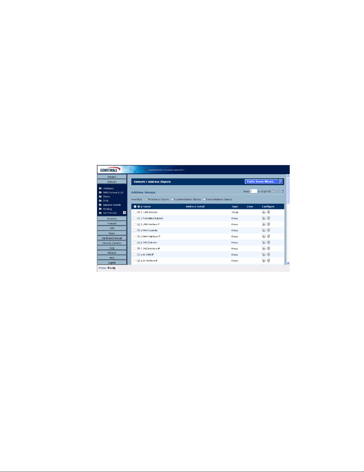
C
HAPTER
13:
Configuring Address Objects
example “My Access Point” with a MAC address of “00:06:01:AB:02:CD”. MAC Address objects
are used by various components of Wireless configurations throughout SonicOS.
Address Object Groups
SonicOS Enhanced also as well as the ability to group Address Objects into Address Object Groups.
Groups of Address Objects can be defined to introduce further referential efficiencies. Groups can
comprise any combination of Host, Range, or Network Address Objects. MAC Address Objects
should be grouped separately, although they can safely be added to Groups of IP-based Address
Objects, where they will be ignored when their reference is contextually irrelevant (e.g. in a NAT
Policy). For example “My Public Group” can contain Host Address Object “My Web Server” and
Range Address Object “My Public Servers”, effectively representing IP Addresses 67.115.118.66 to
67.115.118.90 and IP Address 67.115.118.110.
Creating and Managing Address Objects
The Network>Address page allows you to create and manage your Address Objects.
You can view Address Objects in the following ways using the View Style menu:
• All Address Objects - displays all configured Address Objects.
• Custom Address Objects - displays Address Objects with custom properties.
• Default Address Objects - displays Address Objects configured by default on the SonicWALL
security appliance.
Sorting Address Objects allows you to quickly and easily locate Address Objects configured on the
SonicWALL security appliance.
Note: An Address Object must be defined before configuring NAT Policies, Access Rules, and
Services.
Navigating and Sorting the Address Objects and Address Groups Entries
The Address Objects and Address Groups tables provides easy pagination for viewing a large
number of address objects and groups. You can navigate a large number of entries listed in the
Address Objects or Address Groups tables by using the navigation control bar located at the top right
of the tables. Navigation control bar includes four buttons. The far left button displays the first page of
the table. The far right button displays the last page. The inside left and right arrow buttons moved the
previous or next page respectively.
80
SONICWALL SONICOS ENHANCED 2.5 ADMINISTRATOR’S GUIDE
Page 96

You can enter the policy number (the number listed before the policy name in the # Name column) in
the Items field to move to a specific entry. The default table configuration displays 50 entries per
page. You can change this default number of entries for tables on the System>Administration page.
You can sort the entries in the table by clicking on the column header. The entries are sorted by
ascending or descending order. The arrow to the right of the column entry indicates the sorting status.
A down arrow means ascending order. An up arrow indicates a descending order.
Default Address Objects and Groups
The Default Address Objects view displays the default Address Objects and Address Groups for
your SonicWALL security appliance. The Default Address Objects entries cannot be modified or
deleted. Therefore, the Notepad (Edit) and Trashcan (delete) icons are dimmed. The following lists
the default Address Objects and Address Groups for the PRO 5060.
Network > Address Objects
SonicWALL PRO 5060
Default Address Objects
• X0 IP IP
• X0 Subnet
• X1 IP Host
• X1 Subnet
• X2 IP
• X2 Subnet
• X3 IP
• X3 Subnet
• X4 IP
• X4 Subnet
• X5 IP
• X5 Subnet
• Default Gateway
• Secondary Default Gateway
• SonicPoint
SONICWALL SONICOS ENHANCED 2.5 ADMINISTRATOR’S GUIDE
81
Page 97

C
HAPTER
13:
Configuring Address Objects
Default Address Groups
• LAN Subnets
• Firewalled Subnets
• LAN Interface IP
• WAN Subnets
• WAN Interface IP
• DMZ Subnets
• DMZ Interface IP
• ALL WAN IP
• All Interface IP
• All X0 Management IP
• All X1 Management IP
• Custom Subnets
• Custom Interface IP
• All SonicPoints
• All Authorized Access Points
• WLAN Subnets
• WLAN Interface IP
SonicWALL PRO 4060
Default Address Objects
• LAN Primary IP
• LAN Primary Subnet
• WAN Primary IP
• WAN Primary Subnet
• X2 IP
• X2 Subnet
• X3 IP
• X3 Subnet
• X4 IP
• X4 Subnet
• X5 IP
• X5 Subnet
• Default Gateway
• Secondary Default Gateway
• WAN Remote Access Networks
• VPN DHCP Clients
• LAN Remote Access Networks
• SonicPoint
82
SONICWALL SONICOS ENHANCED 2.5 ADMINISTRATOR’S GUIDE
Page 98

Default Address Groups
• LAN Subnets
• Firewalled Subnets
• WAN Subnets
• DMZ Subnets
• ALL WAN IP
• All Interface IP
• All X0 Management IP
• All X1 Management IP
• All SonicPoints
• All Authorized Access Points
• LAN Interface IP
• WAN Interface IP
• DMZ Interface IP
• WLAN Subnets
• WLAN Interface IP
• Wireless2 Subnets
• Wireless2 Interface IP
Network > Address Objects
SonicWALL PRO 3060
Default Address Objects
• LAN Primary IP
• LAN Primary Subnet
• WAN Primary IP
• WAN Primary Subnet
• X2 IP
• X2 Subnet
• X3 IP
• X3 Subnet
• X4 IP
• X4 Subnet
• X5 IP
• X5 Subnet
• Default Gateway
• Secondary Default Gateway
• WAN Remote Access Networks
• VPN DHCP Clients
• LAN Remote Access Networks
• SonicPoint
SONICWALL SONICOS ENHANCED 2.5 ADMINISTRATOR’S GUIDE
83
Page 99

C
HAPTER
13:
Configuring Address Objects
Default Address Groups
• LAN Subnets
• Firewalled Subnets
• WAN Subnets
• DMZ Subnets
• ALL WAN IP
• All Interface IP
• All X0 Management IP
• All X1 Management IP
• All SonicPoints
• All Authorized Access Points
• LAN Interface IP
• WAN Interface IP
• DMZ Interface IP
• WLAN Subnets
• WLAN Interface IP
• Wireless2 Subnets
• Wireless2 Interface IP
SonicWALL PRO 2040
Default Address Objects
• LAN Primary IP
• LAN Primary Subnet
• WAN Primary IP
• WAN Primary Subnet
• X2 IP
• X2 Subnet
• X3 IP
• X3 Subnet
• X4 IP
• X4 Subnet
• X5 IP
• X5 Subnet
• Default Gateway
• Secondary Default Gateway
• WAN Remote Access Networks
• VPN DHCP Clients
• LAN Remote Access Networks
• SonicPoint
84
SONICWALL SONICOS ENHANCED 2.5 ADMINISTRATOR’S GUIDE
Page 100

Default Address Groups
• LAN Subnets
• Firewalled Subnets
• WAN Subnets
• DMZ Subnets
• ALL WAN IP
• All Interface IP
• All X0 Management IP
• All X1 Management IP
• All SonicPoints
• All Authorized Access Points
• LAN Interface IP
• WAN Interface IP
• DMZ Interface IP
• WLAN Subnets
• WLAN Interface IP
• Wireless2 Subnets
• Wireless2 Interface IP
Network > Address Objects
Adding an Address Object
To add an Address Object, click Add button under the Address Objects table in the All Address
Objects or Custom Address Objects views to display the Add Address Object window.
1
Enter a name for the Network Object in the Name field.
2
Select Host or Range or Network from the Type menu.
3
If you select Host, enter the IP address and netmask in the IP Address and Netmask fields.
4
If you selected Range, enter the starting and ending IP addresses in the Starting IP Address and
Ending IP Address fields.
5
If you selected Network, enter the network IP address and netmask in the Network and Netmask
fields.
6
Select the zone to assign to the Address Object from the Zone Assignment menu. You can
choose LAN, WAN, DMZ, or VPN.
Creating Group Address Objects
As more and more Address Objects are added to the SonicWALL security appliance, you can simplify
managing the addresses and access policies by creating groups of addresses. Changes made to the
group are applied to each address in the group.
SONICWALL SONICOS ENHANCED 2.5 ADMINISTRATOR’S GUIDE
85
 Loading...