

Page 1

SonicWALL
SonicOS 2.x Enhanced
Quick Start Guide
Rev 1.1
February 2004
Page 2
Sonic OS 2.x Quick Start Guide
)
0.0.0.1 /
Introduction
This guide walks you through the steps required to configure a typical customer network using the
new SonicOS 2.x Enhanced firmware. If you are familiar with Sonicwall’s existing products and
firmware, this guide will help you make the transition from those products to the next generation of
Sonicwall firmware.
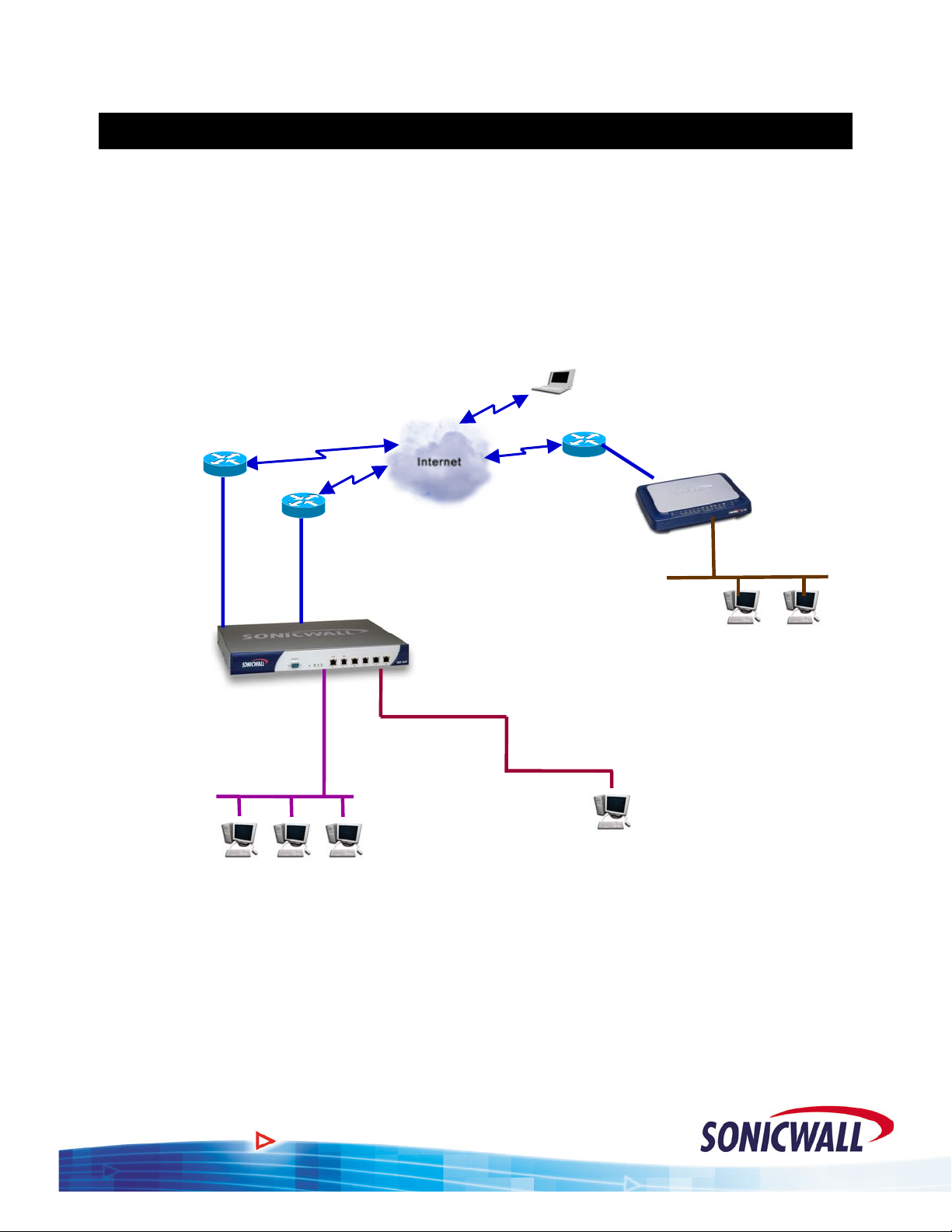
The example network used throughout this guide is illustrated below:
T1
Router IP: 208.48.32.1 / 29
WAN 1 (X1)
208.48.32.2 / 29
192.168.168.168 /
LAN (X0)
192.168.168.1 / 24
Default Gateway
192.168.168.168
WAN 2 (X2)
PPPoE DSL
SonicWALL
PRO 4060
1
DMZ (X3
Mail Server
192.168.168.4 / 24
24
Remote User with Global
VPN Client
WAN
PPPoE DSL
LAN
192.168.1.1 / 24
Default Gateway
10.0.0.1 / 24
Default Gateway 10.0.0.1
Public WWW Server
10.0.0.2 / 24 (208.48.32.3)
SonicWALL
TZ 170e
192.168.1.1/24
1
Page 3

Sonic OS 2.x Quick Start Guide
Basic WAN & LAN Configuration
Refer to the Sonicwall Quick Start Guide included on the product CD.
Security Zones and Objects
There are several new concepts introduced with SonicOS 2.x Enhanced firmware. In this section,
we’ll discuss the Security Zones and Objects. When configuring the new products, you will need to
define your Security Zones early in the setup process so that your rules, NAT entries, and objects
will be easier to work with.
Security Zones - Overview
Sonicwall’s fourth generation appliances extend the previous architecture beyond the LAN, WAN,
and DMZ. The new products, when loaded with the Enhanced firmware, have six user-definable
interfaces. The first two interfaces (X0 and X1) are fixed interfaces, permanently bound to the LAN
and WAN zones, respectively. The remaining four interfaces, X2-X5, can be configured and bound
to any Zone.
The multiple interfaces allow the user to segment their network into a more manageable, secure
infrastructure. It also allows the user to have multiple physical segments grouped together.
This concept of multiple segments, or interfaces, logically grouped together is called Security
Zones. The Security Zone permits the user to name the Zone in a user-friendly way and to write
security rules that apply to all the segments in a Zone, without needing to address each physical
interface individually. In our example, we have two interfaces (X1 and X2), used for WAN loadbalancing and failover. If we group the two interfaces in the WAN Zone, we will only need to write
one set of firewall rules that will apply regardless of which interface is active. This greatly
simplifies the firewall rule base. The pre-defined Security Zones are not modifiable and are defined
as follows:
WAN – This Zone can consist of either one or two interfaces. If using the WAN-WAN
capability, you need to add the second Internet interface to the WAN Zone.
LAN – This Zone can consist of one to five interfaces, depending on your network design.
Even though each interface will have a different network subnet attached to it, when
grouped together they can be managed as a single entity.
DMZ – This is the Demilitarized Zone you are probably familiar with from the existing
Sonicwall product line. This Zone is normally used for publicly accessible servers.
This Zone can consist of one to four interfaces, depending on you network design.
VPN - This predefined Zone is used for simplifying secure, remote connectivity. It is the
only Zone that does not have an assigned physical interface.
NOTE – Even though you may group interfaces together into one Security Zone, this does not
preclude you from addressing a single interface within the Zone.
2
Page 4
Sonic OS 2.x Quick Start Guide
Creating a Custom Zone
There are four fixed Zone types: Trusted, Untrusted, Public and Encrypted. Only the number of
interfaces limits the number of Zone instances for
Zone type (i.e. the WAN) is reserved for the WAN interface(s). The
special system Zone comprising all VPN traffic and doesn’t have any associated interface.
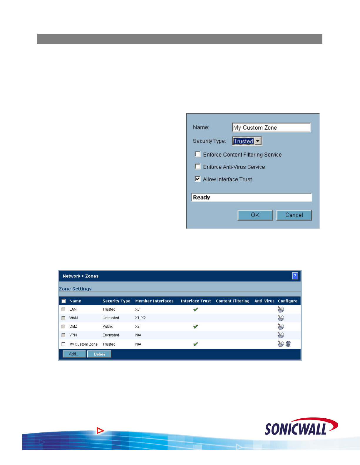
To create a custom zone, proceed as follows:
1. Select the Zones option under the Network
button of the GUI.
2. Click the Add button and the Add Zone
pop-up is displayed.
3. Name your Zone as desired.
4. Select whether the Zone is Trusted or
Public.
5. If Content Filtering is desired, select the
checkbox.
Trusted and Public Zone types. The Untrusted
Encrypted Zone type is a
6. If AV enforcement is desired, select the
checkbox.
7. If multiple interfaces are assigned to this
zone, selecting the Allow Interface Trust
option automatically adds the required access rules to allow hosts on those interfaces to
communicate with one another.
8. Click OK to save your settings. The new custom Zone is displayed in the Zones window.
3
Page 5
Sonic OS 2.x Quick Start Guide
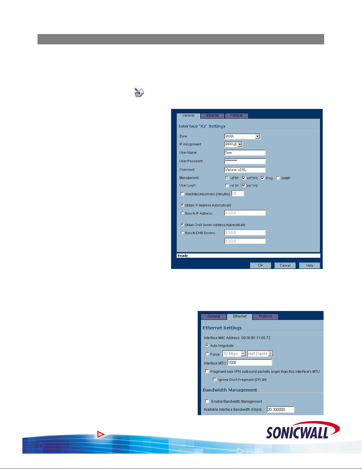
Security Zones - Configuration
The following will guide you through the process of configuring and assigning interfaces to
Security Zones:
1. We start out with the LAN and WAN interfaces as previously defined.
2. Click the configure icon (
) associated with the X2 interface.
3. Select the ZONE as WAN and the IP
assignment as PPPoE.
4. Add the User Name and Password
assigned to the PPPoE DSL account.
5. Enter a Comment if desired.
6. Decide if you want to allow
Management and User Logins on
this interface.
7. If the ISP provided you with a Static
IP address, select ‘Specify IP
Address’ and enter the assigned
Static IP.
8. If you want to set your own DNS
servers, as opposed to the DNS
servers automatically provided by
the PPPoE connection, click ‘
Specify
DNS Servers’ and enter the values.
Select th
9. e Ethernet tab.
NOTE – Even though the Sonicwall auto-negotiates the Ethernet settings, you should make it a
habit to force the settings to match the connected network equipment.
0. Select the ‘Force’ checkbox and enter the
1
appropriate values for the DSL modem
connected to the X2 interface.
11. te changes to
If required, make the appropria
the MTU and fragment settings based on your
configuration. For normal installations,
changes should not be required.
12. , enter the
If using Bandwidth Management
available bandwidth for this DSL connection
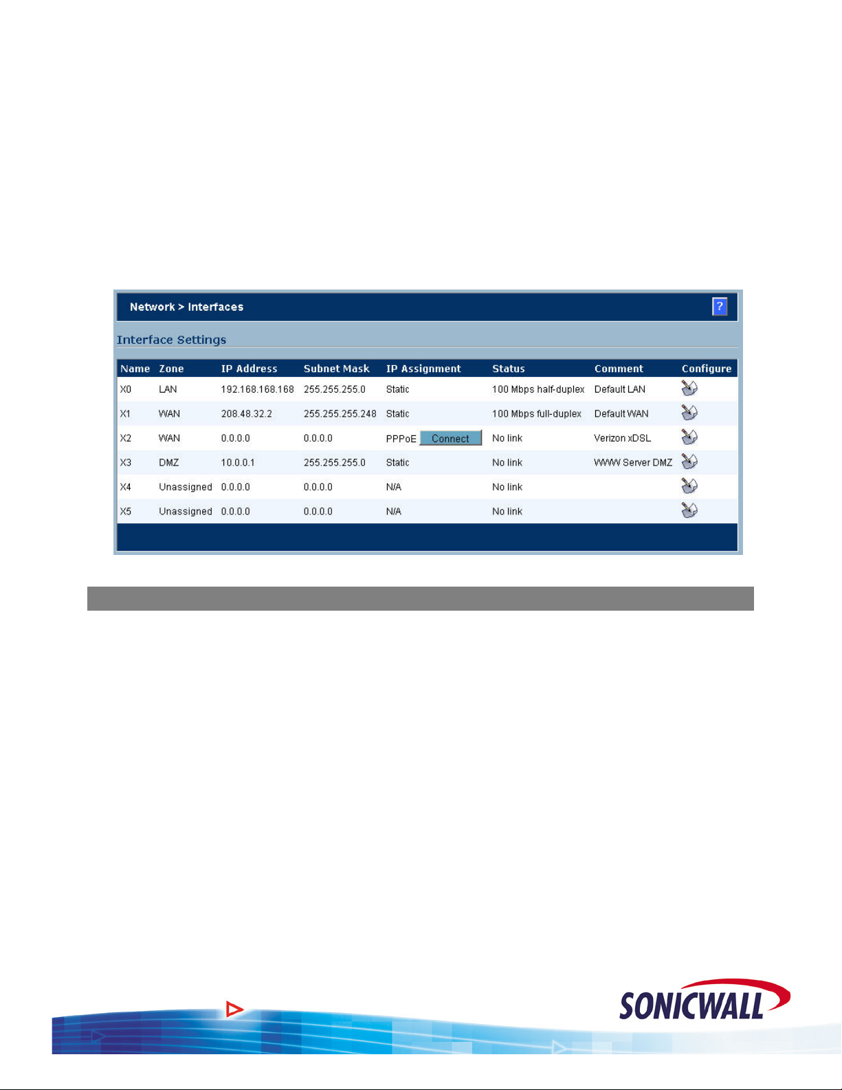
13.
Click OK to save your settings. The new
WAN interface is displayed in the settings
14. r
We will also need a DMZ configured for ou
installation. Click the configure icon associate with the X3 interface.
.
:
d
4
Page 6
15.
Select the Zone as DMZ.
Sonic OS 2.x Quick Start Guide
16. Enter the IP address assign
ed to the X3 interface. Enter the network mask assigned to the
interface.
17. Enter your comments as applicable.
18. Decide if you want to allow Managem
19. Select the Ethernet tab. As above, make the appropriate entries based on the e
ent and User Logins on this interface.
quipment to be
installed on the DMZ Zone.
20. Click OK to save your settings. The new DMZ interface is displayed in the settings.
Objects/Groups - Overview
S of Objects to your security policy. Objects are either
onic OS Enhanced introduces the concept
pre-defined or user-defined elements that can be used by themselves or in groups. Objects relate t
network elements (hosts, subnets or ranges), users, and services. Throughout the new Enhanced
firmware, we will need to define objects and groups in order to create the desired security policy.
Example 1 - We want to write firewall rules to allow mail in to and out from our mail server.
Instead of just using the mail server’s IP address, we’ll create an Address Object called ‘Mail
Server’ and write our firewall rules using this object. If we ever change the address of our mail
server, just a simple change of the object will ensure that the address is changed wherever it may be
in use.
Exampl
e 2 – We would like to block users from accessing Instant Messengers during work hours.
We know that the IM services need to connect to certain servers and we know what the IP address
ranges are for those servers. The problem is, there are a lot of ranges! The solution: create address
objects for each of the IP ranges. Add those address objects to a group called ‘Instant Messengers’,
and write a rule that denies all access to the Instant Messenger group. You’ll see later on that this
will result in a single firewall rule, instead of the six or more that would have been required without
groups.
The sam
e concept of creating an IP address object or group also works for Users and Services.
o
5
Page 7

Sonic OS 2.x Quick Start Guide
Objects and Groups - Configuration
T ting objects and groups. We will use the
he following will guide you through the process of crea
Instant Messenger example from above.
Define the Objects:
1. Select the Addre
Network button
ss Objects option under the
of the GUI.
2. Click the Add button under Address
Objects.
3. Enter an applicable name for the obje
4. Select the object type (Host, Range, or
Network).
NO gs will be slightly different for
TE – Settin
other objects. For the Mail Server in the
example, select the Host type. For the
5. Enter
VPN, select the Network type.
the Starting and Ending IP addresses.
6. Select which Zone the range is located on.
7. Click OK to save your entries. Repeat the st
services, defining all IP addresses and netw
Address Objects displayed.
ct.
eps above for the other Instant Messenger
orks. When completed, you will have a list of
6
Page 8

Sonic OS 2.x Quick Start Guide
8. Repeat the steps above to define other address objects required for your installation. In the
case of our example, you’ll need to create objects for:
a. Web Server (10.0.0.2/32)
b. Mail Server (192.168.168.4/32)
c. Local Pro 4060 LAN for the VPN (192.168.168.0/24)
d. Remote TZ170 LAN for the VPN (192.168.1.0/24)
Define the Group:
1. Click the Add Group b
under Address Groups.
Enter a n
2. ame for the
utton
Address Group.
3. ress
Select the IM add
objects previously defi
ned
and click the -> button to
move them into your grou
4. cted,
When they are all sele
click OK
to save your
p.
selections.
That’s it! Later, we’ll make use of this group in a rule to block IM access.
7
Page 9

Sonic OS 2.x Quick Start Guide
Firewall Access Rules
W uch more functionality and flexibility when configuring
ith Sonic OS Enhanced, you will find m
Firewall Access Rules. However, rule configuration requires advance planning and depends on the
proper configuration of Interfaces, Zones, NAT Policies, Network Address Objects, Service
Objects, and Schedules. Now that we’ve covered Interfaces, Zones, and Address Objects, let’s
compare rule creation on SonicOS Enhanced to Sonicwall 6.x firmware.
“Public LAN Server”
The most common access rule
created in 6.x firmware is the
“Public LAN Server”.
Specifying a “Public LAN
Server” in 6.x firmware
automatically took care of
everything for the admin
behind the scenes – NAT,
service (protocol/port)
definition, firewall rule, etc
Referring to the screen shot, if
ublic access to an SMTP server
p
was required, you could simply
supply the private IP addre
that server next to “Send Email”
in the “Public LAN Server”
field.
Completing the same
at we have a Network Address Object defined that contains the actual IP address of the SMTP
th
server. From our work in previous sections, we see that the “Mail Server” object does indeed exist.
Next, we must establish a NAT policy for the mail server:
istrator
.:
ss of
task with SonicOS Enhanced requires a few more steps. First, we must ensure
8
Page 10

Mail Server NAT Policy:
To create an Inbound NAT policy for our Mail Server:
1. Select the NAT Policies option
under the Network button of the
GUI.
2. Click the ADD button.
3. For Original Source, select ANY.
Allow E-Mail from anywhere on
the Internet.
4. For Translated Source, select
Original. We want to leave the
original source IP address alone.
5. For Original Destination, select
WAN Primary IP. Incoming mail
is being sent to the routable WAN
IP of the Sonicwall.
Sonic OS 2.x Quick Start Guide
6. For Translated Destination, select
the Mail Server address object.
This causes the incoming mail to
be routed to the private IP address (192.168.168.4) defined by the Mail Server address
object.
7. For Original Service, select SMTP (Send E-Mail). We only want this translation to work for
E-Mail.
8. For Translated Service, select Original. Our mail server is expecting SMTP on port 25, so
we leave the service as the original, no service translations required.
9. For Inbound Interface, select X1 (the primary WAN).
10. For Outbound Interface, select ANY.
11. Click OK to add the NAT policy.
Mail Server Firewall Policy:
This NAT policy will take any TCP packets coming in on the primary WAN interface that are
destined for port 25, and redirect them to the IP address of the Mail Server. This is a great start to
allowing access to our mail server, but we’re not done yet – next we must specify an Access Rule
allowing the traffic to pass through the firewall.
First, we must ensure that we place the access rule correctly in the Zone matrix. The Zone concept
essentially creates a matrix of rulesets, with each ruleset applying to traffic
from one zone to
another. Since this rule will apply to traffic coming in from the WAN zone and destined for the
LAN zone, we’ll need to edit the appropriate rules as follows:
9
Page 11

Sonic OS 2.x Quick Start Guide
1. Click the intersection of the WAN (on the left) and LAN (on the top) to display any rules
applicable for incoming packets from the WAN to the LAN.
2. Click ADD, to create a new
entry in the WAN > LAN
ruleset for our Mail Server.
3. Select the ALLOW radio
button.
4. For Service, select SMTP
(Send E-Mail). We only want
to allow E-Mail in to our mail
server.
5. For Source, select ANY. Allow
incoming E-Mail from any
location.
NOTE – Unlike the 6.x firmware,
the firewall rule is written
for the routable WAN IP
address, not the private IP
address of the Mail
Server.
6. For Destination, select WAN Primary IP. All incoming mail is being sent to the IP address
assigned to the WAN interface.
7. For Users Allowed, select all. You should not restrict E-Mail by using User Level
Authentication.
8. For Schedule, select Always On. We want to always allow incoming E-Mail.
9. Add your own comments as desired.
10. Click OK to add the new firewall rule.
10
Page 12

Sonic OS 2.x Quick Start Guide
While there are many other possibilities for creating Access Rules in SonicOS Enhanced, this
“Public LAN Server” example should give you an understanding of where to start. In this section,
we saved a couple fields for future explanation, so let’s talk about them now:
User Level Authentication and Schedules
Back in the “Objects” section we created an Address Object Group called “Instant Messengers”.
Let’s put this group to use in a rule, and combine it with User-Level Authentication (ULA). This
combination will allow us provide IM services on a user-by-user basis. Then we’ll take it one step
further, and use a schedule to apply the rule during certain days and times only.
NOTE – Before creating the rule, you must first ensure th at the user and/or group exist. User
level authentication can be accomplished with either the built-in, internal User database
of the Sonicwall, or via a Radius server.
Create User(s) & Group(s):
You can use the following steps to create additional Users and Groups for other purposes, such as
VPN Client access.
To create a User and associated Group:
1. From the GUI, select the USERS option,
and then LOCAL USERS.
2. Click the ADD USER button.
3. Enter the User’s.Name and Password.
Click OK.
4. Repeat the previous steps to create
additional users, as required.
5. Select LOCAL GROUPS and then select
ADD GROUP.
6. Enter a name for the Group (we called
ours “Allowed IMers”).
7. Select the MEMBERS tab.
8. Select the User we previously created and
click the “->” button to make them a
Member of the group. Repeat for
additional Users, as required.
9. Click OK.
Create Firewall Rule:
To create the Firewall rule to limit Instant Messenger usage to only those in the group:
1. From the GUI, select the FIREWALL option.
2. Click the intersection of the LAN (on the left) and WAN (on the top) to display any rules
applicable for outgoing packets from the LAN to the WAN.
11
Page 13

Sonic OS 2.x Quick Start Guide
3. Click ADD, to create a new
entry in the LAN -> WAN
ruleset for our IM users.
4. Select the ALLOW radio
button.
5. For Service, select ANY. We
want to block all access to the
IM registration sites.
6. For Source, select LAN
Subnets. This will apply the
rule to all networks in the LAN
Subnets group.
7. For Destination, select the
custom address object group,
Instant Messengers. You can
add additional IM sites as
required.
8. For Users Allowed, select the custom user group, Allowed IMers.
9. For Schedule, select Always On. Or, you can select a predefined schedule, such as After
Hours. This limits the user’s access to IM programs to only non-work hours. You can also
create your own schedule, if desired.
10. Add your own comments as desired.
11. Click OK to add the new firewall rule.
Note that in the “Users Allowed” field we’ve placed the “Allowed IMers” user group. This means
that the rule will only apply to users who have first logged in with the appropriate username and
password. To use IM programs, a user would first launch a web browser and point it to the
Sonicwall’s LAN IP address (
http://192.168.168.168, or whatever that address may be). After
supplying the username and password, the user will be authenticated and will then have rights to use
this rule – in other words, they can launch those IM clients!
Building VPNs
With Sonic OS Enhanced, you will find all of the VPN capabilities of the previous firmware and
more. Some of the new features are:
* The ability to define both a Primary VPN Gateway and a Secondary VPN Gateway for use
in the event the primary is unavailable.
* For interoperability, the ability to define whether to use an IP Address, Domain Name, E-
Mail Address, or the Sonicwall Identifier as a means of authenticating IKE negotiations.
* The ability to specify both the local protected network and the remote network, allowing a
level of granularity that wasn’t before available.
12
Page 14

Sonic OS 2.x Quick Start Guide
* The ability to NAT traffic as it enters the VPN Tunnel, or as it exits (inbound or outbound),
and the capability to have firewall rules specified on VPN traffic.
Defining the Security Associations (SA)
For the purpose of this example, we will keep the VPN configuration simple. Ref er to the network
diagram at the beginning of the document for the specifics. You should have already defined
Address objects for the local network (behind the 4060) and the remote network (behind the
TZ170).
On the Pro 4060, define the SA as follows:
1. From the GUI, select the VPN
option, and then click ADD.
2. For IPSec Keying Mode, select IKE
using Preshared Secret.
3. For Name, enter an appropriate n
for this VPN SA.
4. For both the IPSec Primary and
Secondary Gateways, enter 0.0.0.0.
The remote TZ170 receives a
dynamic IP address from the ISP, so
an Aggressive Mode IKE is r
5. Secret, enter an
For Shared
equired.
appropriate combination of
characters and numbers.
6. ect
For the Local IKE ID, sel
Sonicwall Identifier and enter
the
serial number of the Pro 4060.
7.
For the Remote IKE ID, select
Sonicwall Identifier and enter th
serial number of the TZ170.
8.
Select the Network Tab.
9. For the Local Network, ch
oose the
address object previously defined.
For this example, we created an
address object for the LAN subne
connected to the X0 interface
(192.168.168.0/24). The VPN
will
only allow traffic from the X0 IP
Subnet to the remote TZ170.
ame
e
t
10. ect the
For Destination Networks, sel
previously defined address object for
the network located behind the TZ170
(192.168.1.0/24)
13
Page 15

Sonic OS 2.x Quick Start Guide
11.
Select the Proposal tab.
12. For Exchange, select Ag
gressive
Mode. Remember, the TZ170
receives a dynamic IP address
from the ISP.
13. Select the rest of the Phase 1 and
2 proposal settings as required.
Ensure that they match up with
the settings you make on the
TZ170.
14. not use any of the
We will
Advanced Setting for this
example.
15. Click OK.
For the TZ170, we assume that it is also runnin
follows:
om the GUI, select the VPN
1. Fr
option, and then click ADD.
g the Enhanced software. Define the TZ170 SA as
2. ct
For IPSec Keying Mode, sele
IKE using Preshared Secret.
3. te
For Name, enter an appropria
name for this VPN SA.
4.
For the IPSec Primary
Gateway, enter 208.48.
This is the IP address assigne
to the X1 WAN interface of the
32.2.
d
Pro4060.
5. ec Secondary
For the IPS
Gateway, enter 0.0.0.0. Th
e X2
WAN interface of the Pro 4060
receives a dynamic IP via
PPPoE. If it was a static IP, you
could enter its IP as the IPSe
c
Secondary Gateway.
6. same value as the Pro 4060 Shared Secret.
For Shared Secret, enter the
7. For the Local IKE ID, select Sonicwall Identifier and enter the serial nu
mber of the TZ170.
14
Page 16

Sonic OS 2.x Quick Start Guide
8. For the Remote IKE ID, select
Sonicwall Identifier and enter the
serial number of the Pro 4060.
9. Select the Network Tab.
10. For the Local Network, choose
LAN Primary Subnet. This is a
pre-defined address object for t
he
LAN interface of the TZ170.
11. For Destination Networks, select
the previously defined address
object for the network located
behind the Pro 4060
(192.168.168.0/24)
12. Select the Proposal tab.
13. For Exchange, select Aggressive
Mode. Remember, the TZ170
receives a dynamic IP address
from the ISP.
14. Select the rest of the Phase 1 and
2 proposal settings as required.
Ensure they match up with the
settings you’ve made on the Pro
4060.
15. Select the Advanced tab.
16. Check (turn on) the Enable Keep
Alive option. This will keep the
tunnel active and will renegotiate
the tunnel if the WAN IP of the
TZ170 changes.
17. Click OK.
18. You should now be able to
communicate between the two
Sonicwalls via the VPN.
15
Page 17

Sonic OS 2.x Quick Start Guide
WAN-WAN Load Balancing & Fail Over
SonicOS Enhanced provides the capability to connect two WAN links and configure them for Load
Balancing and/or Fail Over. This is the perfect feature for customers who want to back up their T1
lines with DSL or Cable. The dual WAN links can be setup either as Active-Active or ActivePassive. Depending on your customer’s requirements, you’ll need to determine which set up best
fits their needs.
Active-Active This provides outbound load balancing between the two WAN links based on one
of the three available algorithms. Inbound load balancing is not directly supported.
However, selected services (E-Mail and VPN) can be configured to failover from
one WAN link to the other. These two scenarios require static IP addresses on both
WAN links.
Link states can be monitored in one of two ways. By default, each WAN link will
be monitored at the physical level. For most applications, customers will also want
to configure Probe Monitoring, which adds monitoring at a logical level using
either TCP connection requests or ICMP. This allows a failure of an upstream
device to be detected.
Active-Passive Only the Primary WAN link is active, unless a link failure is detected. Although
the Secondary link is unused except during a failure of the Primary, greater
redundancy can be achieved for inbound traffic. For example, a third-party
dynamic DNS client could be used to ensure that DNS records always reflect the
currently active WAN link.
WAN Failover
In order to configure the Failover and Load
Balancing feature, you must first configure t
second WAN interface and assign it to the
WAN Zone. For our example, the Secondary
WAN is an xDSL line with a dynamic IP via
PPPoE. You’ll need to configure your
Secondary WAN based on the type of
connection your customer provides.
On the Pro 4060, configure the settings as
follows:
1. From the GUI, select the NETWORK
button and then WAN Failover & LB.
2. To enable outbound load balancing,
click the enable checkbox. With only
this checkbox enabled, the Sonicwall
only tests the physical link status.
he
16
Page 18

3. Customize the probing interval, deactivate, and
reactivate values as required.
NOTE – Be careful with the values you set. Making them
too small may cause the Sonicwall to identify a
link as down even if connectivity was only b
interrupted.
4. Select the Enable Probe Monitoring, if you want to do
both physical and logical link monitoring. If selected,
you will also need to configure the monitoring.
5. Click the configure button.
6. Set up your probe sites, as required, based
on the customer’s needs.
7. Click OK.
Probe Settings Logic
Sonic OS 2.x Quick Start Guide
riefly
AND The AND option requires that
both the
Probe Target and the Optional Probe
Target are active for the link to be
considered UP. Both the Probe Target
and the Optional Probe Target must
have valid entries.
OR The OR option requires that
only one
of the probe targets be active for the
link to be considered UP. The O
ptional
Probe Target is not required when
using the OR logic.
As you can see, you have the option to probe 1 and/or 2 locations for each WAN link to
determine if the link is functioning. You also have the option to probe using a protocol other
than ICMP (ping).
For the Primary WAN, we are testing via DNS to our ISP’s two DNS Servers. If connectivity is
good to
either DNS server, the link is considered UP.
For the Secondary WAN, we are using two public web sites, via ping, for testing the status of
the xDSL link.
17
Page 19

Sonic OS 2.x Quick Start Guide
WAN Load Balancing
As previously mentioned, the Load Balancing capability can be Active-Passive, or Active-Active.
If you decide to use the Active-Active option, you will select one of the three load balancing
algorithms.
Round Robin The Sonicwall balances the outgoing
traffic on a per-destination basis by
examining source and destination IP
addresses.
Spill Over The Sonicwall balances the outgoing
traffic on a spillover basis when a
bandwidth maximum is reached on
the Primary WAN. You must specify
the maximum bandwidth to use on
the Primary WAN before traffic is sent via the Secondary WAN.
Percentage The Sonicwall balances the outgoing traffic on a percentage basis of the total
bandwidth available on the two WAN links. You must specify the percentage of
bandwidth for the Primary WAN link and the Sonicwall automatically allocates the
remaining percentage to the Secondary link.
1. From the GUI, select the type of Load Balancing that fits your customer’s needs.
2. For other than Round Robin, enter the appropriate bandwidth amount or spillover
percentage.
3. Don’t forget to click the Apply button at the top of the page!
NOTE – Before the load balancing is
complete, you must create a NAT
rule for the second WAN
interface.
4. From the GUI, select the Network
button and then the NAT Policies
option.
5. Click the ADD button.
6. For Original Source, select LAN
Subnets. We need to NAT any LAN
traffic outbound through the
Secondary WAN.
7. For Translated Source, select X2 IP.
NAT outbound traffic to the dynamic
PPPoE IP of the Secondary WAN.
8. For Original Destination, select ANY.
Any traffic destined for the Internet.
18
Page 20

Sonic OS 2.x Quick Start Guide
9. For Translated Destination, select Original. We want the traffic to still go to its original
destination.
10. For Original Service, select ANY. Leave the service as the original service.
11. For Translated Service, select Original. Again, we want the traffic to go to its original
destination, via its original service (protocol).
12. For Inbound Interface, select ANY or you could select the X0 LAN interface only.
13. For Outbound Interface, select X2. NAT all outbound traffic to the IP of the X2 Secondary
WAN IP.
14. Click OK to add the NAT policy.
With the addition of the new NAT rule, any load balanced traffic going out through the X2
Secondary WAN link is NAT’ed to its IP address.
19
 Loading...