

Page 1
OWNER’S MANU A L
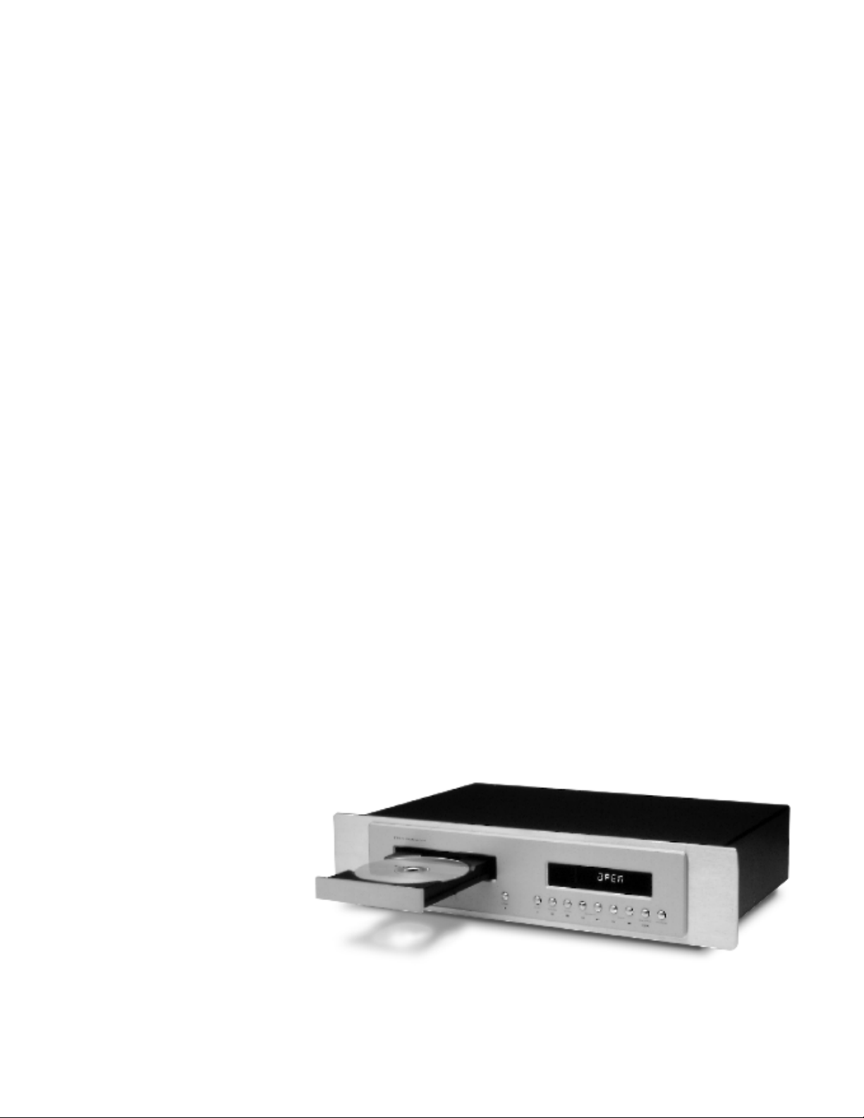
THE SONIC FRONT I ERS SFT-1 TR ANSPORT
Page 2
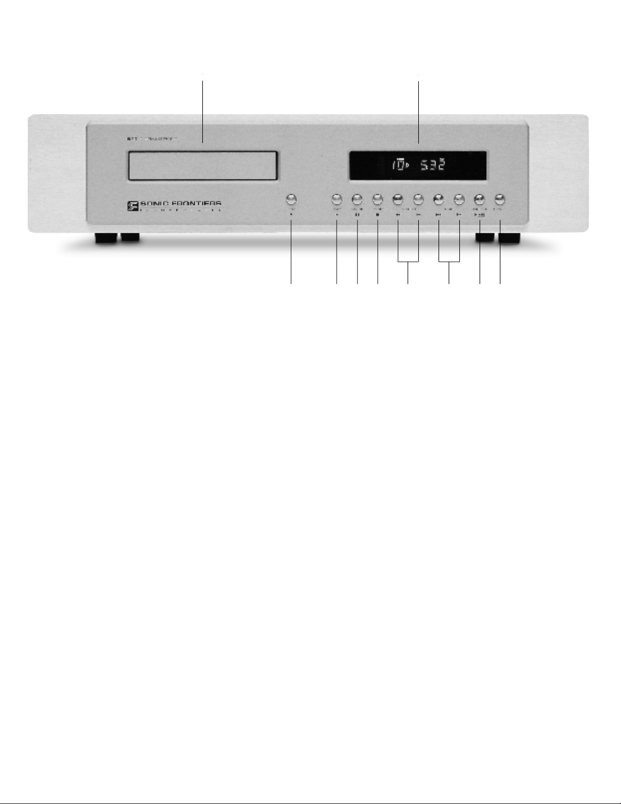
CONTROL FUNCTIONS AND CONNECTIONS
A
C D E F G H I J
B
A
-Loading Drawer - This is the mechanism for loading CDs
for play in the SFT-1. The drawer is opened by depressing the
LOAD (C) button. A CD is placed in the tray‘s circular depression, label side up and lying flat. The drawer is closed, and
the CD is loaded for play, by depressing the LOAD (C) o r
PLAY (D or T) buttons. Although the drawer will also close by
pushing gently on the drawer front, it is recommended that a
button control be exclusively used for this function.
B - Display Window - The display window gives the operating
status of the SFT-1. When a CD is loaded, the total number of
tracks and total time will be displayed. When the SFT-1 is put
in play mode, the track being read is displayed with an arrow
indicating play and is followed by the time of the individual
track. Also displayed are: NO DISC, when power is on and
no CD is in the drawer; and O P E N, PAUSE, REPEAT a n d
P R O G R A M, when these functions are selected.
C - Load Button - When depressed, this button will open and
close the LOADING DRAWER (A). It will also clear any set
functions such as programming, repeat or shuffle from memory.
D
-Play Button - When depressed, this button will put the trans-
port in play mode. During play mode, the CD is being read
and a digital datastream is being transmitted from the chosen
digital output (M through P).
E
-Pause Button - When depressed, this button will stop the
transmission of the digital datastream at the precise moment it is
engaged, and will hold that position until play is resumed by
depressing the PAUSE (E or U) button again.
F - Stop Button - When depressed, this button will stop all func-
tions, taking the CD out of play mode and aligning the transport to the first track or the first programmed track. Depressing
the STOP button when the CD is not in play mode will clear
programmed tracks from memory or clear other selected functions such as SHUFFLE and REPEAT.
G - Search Reverse and Forward Buttons - When de-
pressed and held, these buttons allow a 10 second audible
fast forward or reverse search of a track in play mode. After
the 10 second audible search, the SFT-1 will mute and proceed in a faster search. The time positioning and the track are
shown in the DISPLAY WINDOW (B).
H - Skip Reverse and Forward Buttons - When depress-
ed, these buttons will position the laser to read the start of the
track either before (skip reverse) or after (skip forward) the original position of the laser. The transport may be in the play,
pause, or stop mode. Play will continue forward from this chosen track.
I - Shuffle Button - When depressed before the PLAY button
(D or T), this button will randomize the order in which the tracks
are played.
J - Power Button - When depressed, this button will allow
power to the transport for full-function control, or it will turn off
the SFT-1 when the transport is no longer in use. The MAIN
POWER SWITCH (K), located on the rear of the SFT-1, must
be in the “on” position for this button to work.
Page 3

K L M N O P
K - Main Power Switch - This switch must be in the “on” posi-
tion for the SFT-1 to operate. When the POWER button (J) has
rendered the unit’s control functions off, this switch allows
power to continue to circulate to sections of the transport so the
unit will operate at maximum efficiency with no warm-up time
required. This switch should remain on at all times.
L - Detachable Power Cord Socket - Plug the Detachable
Power Cord into this socket (see Figure 1). The SFT-1 is factory
set for the correct operating voltage for the area in which it is
sold (see shipping box for voltage setting). If a different operating voltage is required, please contact an authorized Sonic
Frontiers dealer, distributor or the factory directly.
M -
H-P/ST (Glass Fibre) Optical Output - If chosen for use,
this digital output must connect to an ST-Optical input on the
D A C .
N
-AES/EBU XLR Output - This digital output conforms to the
AES/EBU (Audio Engineering Society/European Broadcast
Union) standard. If this output is chosen for use, a 110 ohm
balanced cable terminated with XLR plugs should be used for a
connection to the DAC.
NOTE: The XLR jack pin connectors for the SFT-1 are configured as follows: Pin #1 : Ground
Pin #2 : Positive (+) Phase
Pin #3 : Negative (–) Phase
O -
Coaxial BNC Cable Output - This digital output is a BNC
S/PDIF connector. If chosen for use, this digital output should
be connected to an S/PDIF connector on the DAC. The BNC Coaxial cable impedance should be 75 ohms.
P - Coaxial RCA Cable Output - This digital output is an
RCA S/PDIF connector. If chosen for use, this digital output
should be connected to an S/PDIF connector on the DAC. The
RCA - Coaxial cable impedance should be 75 ohms.
Figure 1 - Align socket pins to corresponding holes and push together firmly.
Page 4

FUNCTIONS OF THE SFT-1 REMOTE CONTROL
R
Q
T - Play Button - When depressed, this button will put the trans-
port in play mode. During play mode, the CD is being read
and a digital datastream is being transmitted from the chosen
S
digital output (M through P).
T
U
W
Y
Z
AA
V
X
Y
Z
Q - Power Button-When depressed, this button will allow
power to the transport for full-function control, or it will turn off
the SFT-1 when the transport is no longer in use. The MAIN
POWER SWITCH (K), located on the rear of the SFT-1, must
be in the “on” position for this button to work.
R - Numeric Keypad - This keypad allows tracks to be selected
directly. Punch the desired track number and then the next function (either PLAY or PROGRAM) to complete the selection.
S - Program Button - Tracks selected through the KEYPAD (R)
or S K I P (H or Z) buttons may be programmed for desired playback order by selecting a desired track then pushing the program button. Up to 20 tracks may be programmed into memory for playback. Tracks may only be programmed once;
attempting to program a track twice will clear the track from
memory. To clear the programmed material from memory,
press the STOP (F or AA) button once before programmed play
has begun, or twice consecutively during play.
U - Pause Button - When depressed, this button will stop the
transmission of the digital datastream at the precise moment it is
depressed, and will hold that position until play is resumed by
depressing the PAUSE (E or U) button again.
V - Shuffle Button - When depressed before the PLAY button
(D or T), this button will randomize the order in which the tracks
are played. Depressing this button a second time will clear this
f u n c t i o n .
W -
Repeat Button - When depressed once, this button will
cause a CD in play mode to repeat the tracks in the order they
appear on the CD or to repeat a programmed selection of
tracks in the order they are programmed. When pressed twice,
the Repeat One mode will be activated, causing the currently
selected or playing track to be repeatedly played. Pressing this
button a third time will clear this function.
X -
Scan Button - When depressed, this button will cause the
transport to scan the CD. During this scan the transport will play
the first 10 seconds of each track.
Y -
Search Reverse and Forward Buttons - When depressed and held, these buttons allow a 10 second audible
fast forward or reverse search of a track in play mode. After the
10 second audible search, the SFT-1 will mute and proceed in
a faster search. The time positioning and the track are shown in
the DISPLAY WINDOW (B).
Z - Skip Reverse and Forward Buttons - When depress-
ed, these buttons will position the laser to read the start of the
track either before (skip reverse) or after (skip forward) the original
position of the laser. The transport may be in the play, pause, or
stop mode. Play will continue forward from this chosen track.
A A -
Stop Button - When depressed, this button will stop all func-
tions, taking the CD out of PLAY mode and aligning the transport to the first track or the first programmed track. Depressing
the STOP button when the CD is not in play mode will clear
programmed tracks from memory or clear other selected functions such as SHUFFLE and REPEAT.
Page 5

OPERATION OF THE SFT-1 TRANSPORT
Before plugging in the SFT-1, check to see that the unit is configured
for the correct AC line voltage for country of use. The operating AC
line voltage is indicated on the side of the shipping box. If the SFT-1
Transport is set incorrectly for the country in which it is to be operated, contact the dealer or distributor in your area. If the unit is configured properly, continue with operation.
T R O U B L E S H O O T I N G
If at any time the SFT-1 Transport fails to work properly,
consult this checklist:
If the SFT-1 will not turn on:
1. Check that the Main Power Switch (K) is in the o n p o s i t i o n .
Connect the Detachable Power Cord to the SFT-1 chassis (see
Figure 1) and plug your SFT-1 into the AC power source.
Load the Remote Control with 2 AAA size batteries.
Next choose the most appropriate digital output connector (M
through P). With the appropriate cable connect the SFT-1 to your
DAC’s digital input.
The SFT-1 Transport is now ready for operation. Power the unit
by placing the Power Switch (K) in the ON position. Next
depress the Power Button (J or Q) and load the transport with a
favorite CD. Select desired track(s) and press the Play Button (D
or T). You are now ready to sit back, listen and enjoy.
BREAK-IN TIME
As with all audio electronic products, the ultimate sonic character of the SFT-1 will not be realized until and unless the unit
receives a minimum of approximately 150 hours of signal
break-in time (i.e. the SFT-1 is on and outputting a signal).
2. Check that the AC Detachable Power Cord is plugged into the
SFT-1 Detachable Power Cord Socket (L) and is connected to a l i v e
source of AC power. For instance, if using a power bar, check that
the bar is turned o n.
If the SFT-1 is operating but does not play:
1. Be sure the rest of the system is functioning properly (i.e. DAC,
power amplifiers, cables and connections, etc.).
2. Check that the loading drawer is not jammed by an improperly
loaded CD.
3. Check to ensure the CD has not been put in the transport with the
label side down.
4. Be sure the CD is not damaged and is readable.
If the remote does not function, check to ensure that the two AAA
batteries are fresh.
If these checks fail to correct the operation of the SFT-1 Transport
contact the nearest Sonic Frontiers dealer or Sonic Frontiers directly.
Page 6

SFT-1 PLACEMENT
Be sure the SFT-1 is resting on a hard, flat surface.
SAFETY INSTRUCTIONS
1. Water and Moisture - This product should not be used near
water. To prevent fire or shock hazard, do not expose this
product to rain or moisture.
2. Heat - This product should be situated away from heat
sources such as radiators, heat registers, stoves, or other appliances which produce heat.
3. Power Sources - This product should be connected to an AC
power source of the proper rated voltage. The original shipping container will stipulate the AC voltage this unit can operate with correctly.
4. Cleaning - A regular dusting with a soft, non-abrasive cloth
will generally keep the finish of the faceplate and chassis looking like new. At no time should you allow any liquid to come in
contact with the SFT-1 Transport; it may run into the electronic
circuitry and cause damage which will not be covered under
your warranty.
5. Servicing - Do not open this product. No user serviceable
parts inside. Refer servicing to an authorized service technician.
6. Non-Use Periods - The power cord of this product should be
unplugged from the outlet when left unused for an extended
period of time.
LIMITED FIVE YEAR WARRANTY
Sonic Frontiers, Inc. warrants to the purchaser that each SFT-1
Transport is free of manufacturing defects for a period of five
(5) years from the date of purchase. This five (5) year limited
non-transferable warranty excludes the transport mechanism,
which we warrant for a period of twelve (12) months. To
receive this warranty, the original purchaser must complete and
mail to Sonic Frontiers, within thirty (30) days from the date of
purchase, the enclosed Warranty Registration Card. Sonic
Frontiers, Inc. will then validate the warranty to the original purchaser. This warranty is subject to the following conditions and
l i m i t a t i o n s :
1
. Warranty applies only to the original purchaser.
2. This warranty is void and inapplicable if the product has
been handled other than in accordance with the instructions in
this Owner’s Manual, abused or misused, damaged by accident or neglect or in being transported, or the defect is due to
the product being tampered with, modified or repaired by anyone other than Sonic Frontiers, Inc. or an authorized Sonic
Frontiers repair depot.
3. Warranty does not cover normal maintenance.
4. Sonic Frontiers, Inc. shall not be responsible in any way for
consequential or indirect damages or liabilities resulting from
the use and operation of the product covered herein or resulting from any breach of this warranty or any implied warranty
relating to said product.
PACKING MATERIALS
We recommend that you retain all of the packing material and
shipping boxes for your SFT-1 Transport to be covered by warranty. They are custom designed to prevent shipping damage
from occurring. Sonic Frontiers, Inc. will accept no responsibility for any damage occurring to an SFT-1 Transport that is
shipped in packing material other than the original Sonic
Frontiers packing material.
DISCLAIMER OF LIABILITY
Under no circumstances does Sonic Frontiers, Inc. assume liability or responsibility for injury or damages sustained in the use
or operation of this equipment or for damages to any other
equipment connected to it.
Sonic Frontiers, Inc. reserves the right to make design changes
or improvements without the obligation to revise prior versions.
All specifications are subject to change without notice.
During this stated period, Sonic Frontiers, Inc. will repair or
replace any defective components free of charge. A Return
Authorization Number (RA Number) is required before any
product is returned to our factory for any reason. This number
must be visible on the exterior of the shipping container(s) for
Sonic Frontiers to accept the return.
Units shipped to us without a Return Authorization Number or
without a visible RA Number on the exterior of the shipping
container(s) will be returned to the sender, freight collect.
Units to be repaired by Sonic Frontiers, Inc. must be sent shipping and insurance prepaid by the original purchaser in the
original packing material. A returned product should be accompanied by a written description of the defect and a copy of the
original bill of sale. Repaired units will be returned by Sonic
Frontiers, Inc. shipping and insurance prepaid. The sender’s
name, address and telephone or fax number must accompany
the unit.
All other warranties or conditions either written or implied
are void.
Note: In foreign markets (anywhere outside of Canada and the
USA), the warranty is supplied by the authorized International
Distributor. Exact terms and conditions may vary.
Page 7

SFT-1 TECHNICAL SPECIFICATIONS
Wow and Flutter Below measurable levels
Jitter <2 ps rms, to 40 kHz at the clock
Typically 10 ps rms, at the outputs
independently verified with UltraAnalog’s
(
latest Jitter Analyzer)
Digital Outputs
AES/EBU Balanced on XLR-3 connector
Impedance 110 ohms, ±5%
Level 3.0V p-p typ with 110 ohm load
Tr=Tf 7 ns, typ
SPDIF Single ended RCA connector
Impedance 75 ohms, ±5%
Level 0.5V p-p typ with 75 ohm load
Tr=Tf 8 ns, typ
SPDIF Single ended BNC connector
Impedance 75 ohms, ±5%
Level 0.5V p-p typ with 75 ohm load
Tr=Tf 8 ns, typ
Glass-ST HP HFBR-1414
Power 60 uw into 62 um fibre
Laser,Semiconductor GaAIAs, 0.5 mw, continuous, 790 nm
Sampling Rate 352.8 KHz
DiscRotationVelocity 200-500 rpm (constant linear vel.)
Quantization 16 bits, linear
Error Correction CIRC principle
Number of channels 2 channels, stereo
Dimensions 17” Wide x 11” Deep x 3.5” High
(43 cm x 28 cm x 9 cm)
D a n g e r - Invisible Laser radiation when the
cover is removed from the chassis. Avoid dire c t
e x p o s u re to the beam.
Wa rn i n g - Fast heating (eg. bringing the
mechanism from a cold place into a warm and
humid room) can result in moisture condensing
on the lens. Before operation, the mechanism
should stabilize for at least 4 hours.
This symbol is intended to alert the
user to the presence of uninsulated
“dangerous voltage” within the
product’s enclosure that may be of
sufficient magnitude to constitute
a risk of electric shock to persons.
Weight 17 lbs (7.7 kg), unpacked
Warranty 5 years parts and labor on the unit
1 year on transport mechanism
This symbol is intended to alert the
user to the presence of important
operating and maintenance (servicing)
instructions in the literature accompanying the appliance.
Page 8

We at Sonic Frontiers are sure that you will derive many years
of listening pleasure with your new SFT-1 Transport. This Owner’s
Manual contains important information regarding the operation
and care of the SFT-1. Be sure to read this manual carefully and
follow these instructions in order to keep it looking, operating
and sounding its best.
2790 Brighton Road, Oakville, Ontario, Canada L6H 5T4 Telephone: (905) 829-3838 Facsimile: (905) 829-3033
Sonic Frontiers can be reached from 9:00 a.m. to 6:00 p.m., Eastern Standard Time (E.S.T.), or 24 hours a day by facsimile.
 Loading...