

Page 1
User Manual
Sonic Wave I
3D Sound Processor
Version 3.0.1
Page 2

Page 2 of 72 / Confidential / Version 1.1
Eichweg 6 8154 Oberglatt Switzerland tel +41 (0) 44 850 0838 fax +41 (0) 44 850 0839 pro@sonicemotion.com
www.sonicemotion.com
Table of Contents
SAFETY INFORMATION 5!
INTRODUCTION 6!
THE SOFTWARE 7!
1. SONIC WAVE I TOPOLOGY 8!
HD OPTION 9!
2. SONIC WAVE I HARDWARE 10!
CONNECTIONS 10!
ADAT VERSION 10!
MADI! VERSION 10!
HARDWARE REVISIONS 11!
SYSTEM DONGLE 11!
3. CONTROL ELEMENTS 12!
DISPLAY MENU 12!
HD VERSION 12!
ROTARY CONTROL 12!
BUTTONS 13!
4. SYSTEM CONFIGURATION 14!
SOFTWARE INSTALLATION 14!
PC CONFIGURATION 14!
MAC OS X – SETUP WITHIN VIRTUAL BOX 15!
MAC OS X (HOST): 15!
VIRTUALBOX - NETWORK SETTINGS: 16!
WINDOWS (VIRTUALBOX GUEST): 16!
5. UNDERSTANDING THE FUNCTIONALITIES 17!
LOUDSPEAKERS ASSIGNMENT HIERARCHY 17!
SYSTEM 17!
SUBSYSTEM 17!
WFSMAIN 18!
SUBWOOFERS 18!
SUMMARY 18!
6. THE WAVEDESIGNER - SETTING-UP THE SONIC WAVE I
PROCESSOR 19!
WORKFLOW 19!
USING THE VALUE BOXES 21!
HOW TO STORE PROJECTS/SETTINGS 21!
SPEAKER SETUP 22!
MENU BAR 24!
Page 3

Page 3 of 72 / Confidential / Version 1.1
Eichweg 6 8154 Oberglatt Switzerland tel +41 (0) 44 850 0838 fax +41 (0) 44 850 0839 pro@sonicemotion.com
www.sonicemotion.com
UPPER TOOL BAR 26!
ADD ARRAY DIALOG 28!
TEST TOOL 30!
STATUS BAR 32!
SUBSYSTEM CONTROL 33!
EQUALIZER 34!
SPEAKER MANAGEMENT 37!
OUTPUT ASSIGNMENT 38!
7. CONTROL THE SONIC WAVE I PROCESSOR WITH
WAVEPERFORMER 38!
USING THE VALUE BOXES 38!
CONTROL ELEMENTS 39!
MENU BAR 39!
UPPER TOOL BAR 40!
LEFT TABS 40!
RIGHT TOOL BAR 41!
STATUS BAR 41!
SOURCE POSITIONING PANEL 42!
INPUT PANEL 43!
ROUTING PANEL 45!
EQ PANEL 46!
SYNC PANEL 47!
8. HD OPTION 50!
MEDIA MANAGER CONFIGURATION 50!
UPLOAD AUDIO FILES 52!
9. OSC INTERFACE 53!
OSC SETTINGS 53!
OSC MESSAGES 53!
10. WAVE INTERFACE AU PLUG-IN 59!
INSTALLATION 59!
VIEWER FUNCTION 59!
GROUP SETTINGS 60!
11. MAX MSP PLUG-IN 61!
INSTALLATION OF THE MAX MSP OBJECT 61!
PATCHES 62!
12. SYSTEM UPDATE 63!
13. TROUBLE SHOOTING 64!
14. SYSTEM SPECIFICATIONS 65!
15. PLANNING THE INSTALLATION 66!
SPEAKER SETUP 67!
FRONTAL SYSTEM 67!
SPACING 67!
Page 4

Page 4 of 72 / Confidential / Version 1.1
Eichweg 6 8154 Oberglatt Switzerland tel +41 (0) 44 850 0838 fax +41 (0) 44 850 0839 pro@sonicemotion.com
www.sonicemotion.com
SIDE AND REAR SETUP FOR PERIPHERIC SYSTEMS 68!
SUBWOOFERS 68!
WFS SUPPORT SPEAKERS 68!
SPEAKER REQUIREMENTS 68!
16. SYSTEM TUNING WITH THE BUILT-IN EQ 69!
MEASUREMENT TOOLKIT 69!
LASER METER 69!
MEASUREMENT SOFTWARE AND AUDIO INTERFACE 69!
MEASUREMENT MICROPHONE 69!
TUNING OBJECTIVE 70
BASIC TUNING WITH SPL 70
FINE TUNING WITH EQ 70
Page 5

Page 5 of 72 / Confidential / Version 1.1
Eichweg 6 8154 Oberglatt Switzerland tel +41 (0) 44 850 0838 fax +41 (0) 44 850 0839 pro@sonicemotion.com
www.sonicemotion.com
SAFETY INFORMATION
• This equipment must be EARTHED.
• Only suitably trained personnel should service this equipment.
• Please read and take note of all warning and informative labels.
• Before starting any servicing operation, this equipment must be isolated from the AC supply
(mains) by removing the incoming IEC mains connector.
• Fuses should only be replaced with ones of the same type and rating as that indicated.
• Operate only in a clean, dry and pollutant-free environment.
• Do not operate in an explosive atmosphere.
• Do not allow any liquid or solid objects to come into contact with the equipment.
Should this accidentally occur then immediately switch off the unit and contact your service
agent.
• Do not block ventilation slots.
Page 6
Page 6 of 72 / Confidential / Version 1.1
Eichweg 6 8154 Oberglatt Switzerland tel +41 (0) 44 850 0838 fax +41 (0) 44 850 0839 pro@sonicemotion.com
www.sonicemotion.com
Introduction
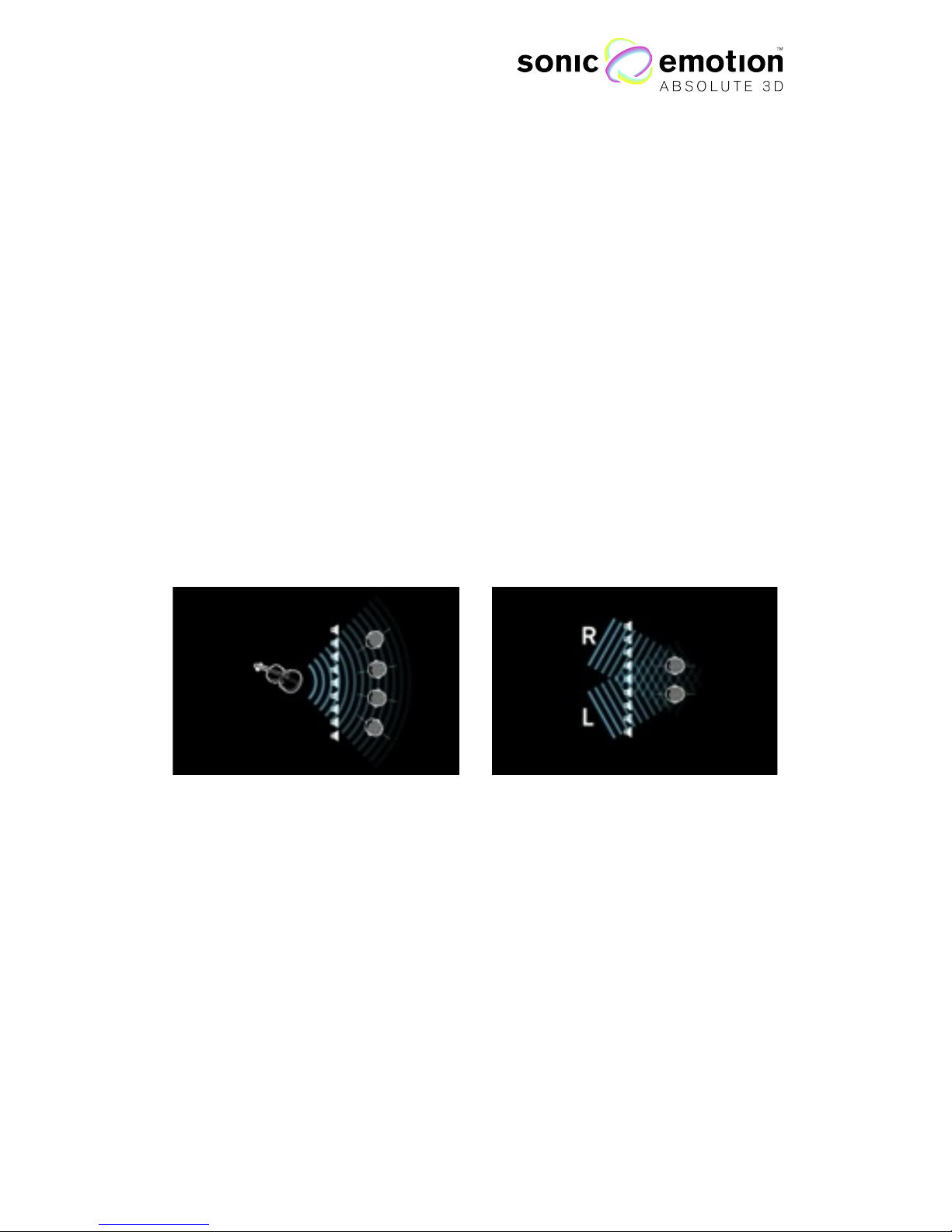
The Sonic Wave I 3D sound processor is specially designed to enlarge the listening
zone of conventional surround sound and enables perfect audio imaging for all
listeners. In conventional setups, only listeners in the center of the loudspeaker array
are in the sweet spot and therefore get the impression that the sound is reproduced
spatially. With the Sonic Wave I, everyone has the same impression of spatial audio
regardless of his or her position. Using Sonic Emotion™ audio processing based on
wave field synthesis (WFS), the Sonic Wave I processor is able to enlarge the sweet
spot to the whole listening area. Stereo or 5.1 content can be rendered using plane
audio waves, which allow for a consistent listening angle of all input channels in the
entire audience. Moreover, audio objects with position information can be rendered
as point sources. In this case, the perspective to the audio source (e.g. instrument,
singer, etc.) remains meaningful within the entire audience. As a result, the listening
experience is dramatically improved, not only in the sweet spot but also in the entire
audience while using the Sonic Wave I.
Point Source
Plane Waves
Figure 1.1
Page 7

Page 7 of 72 / Confidential / Version 1.1
Eichweg 6 8154 Oberglatt Switzerland tel +41 (0) 44 850 0838 fax +41 (0) 44 850 0839 pro@sonicemotion.com
www.sonicemotion.com
The Software
The software component of the Sonic Wave I entails two core tools mainly the Sonic
WaveDesigner and the Sonic WavePerformer.
With the Sonic WaveDesigner application you design and configure your system
according to the loudspeakers set up in the room. This step is done once and let’s
the Sonic Wave I processor calculate the filters and parameters, which are used for
the rendering. Regardless of the amount of speakers and their position, audio
material fed in to the Processor can be positioned as virtual sound sources in the
room.
The Sonic WavePerformer allows you to set the virtual sound sources (stored
media files or live inputs) in the room. The virtual sound sources can be static and
stored as Presets in to the memory of the processor, or are controlled by tools as the
audio unit Plug-In “Wave Interface AU” and because of this dynamic timeline based
sound source movements can be created.
Page 8
Page 8 of 72 / Confidential / Version 1.1
Eichweg 6 8154 Oberglatt Switzerland tel +41 (0) 44 850 0838 fax +41 (0) 44 850 0839 pro@sonicemotion.com
www.sonicemotion.com
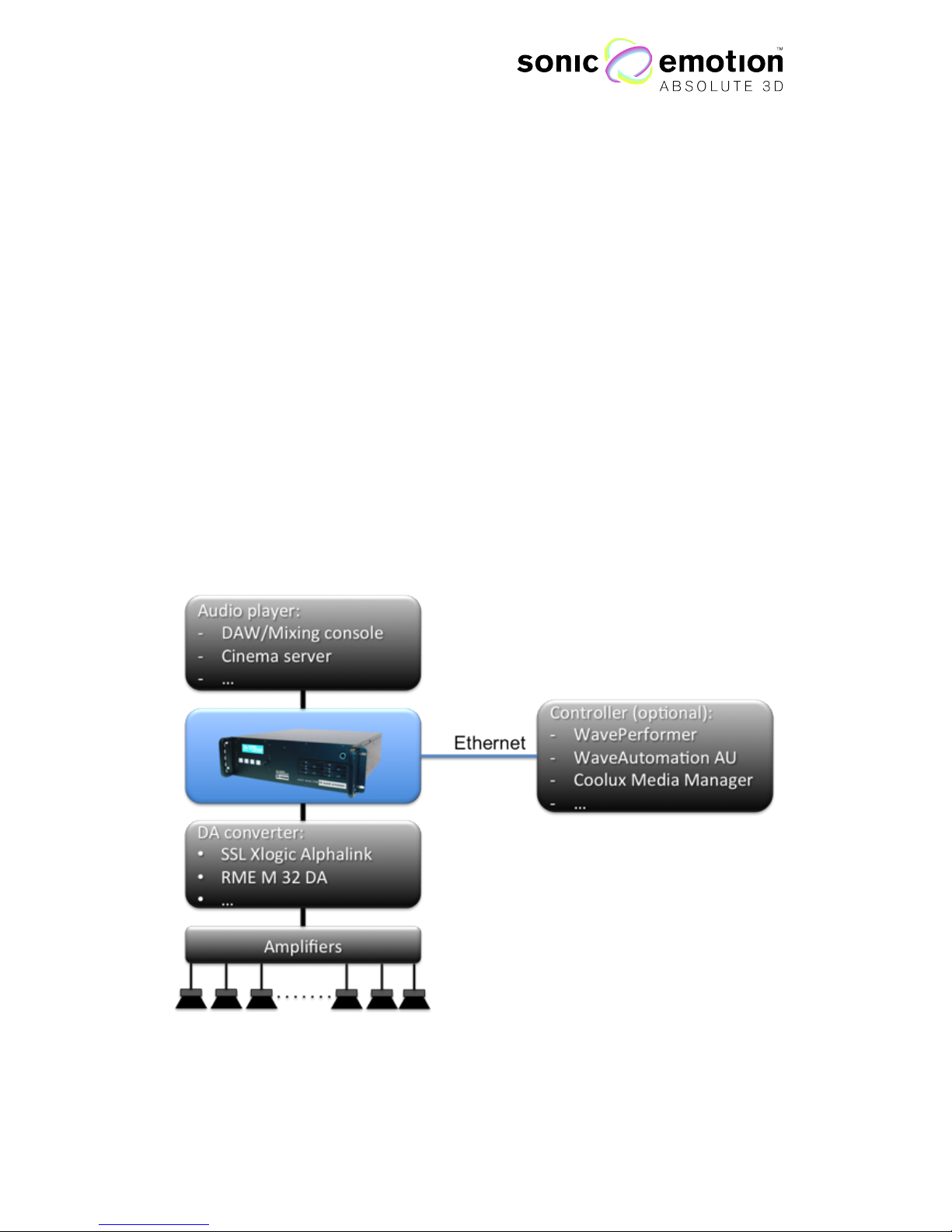
1. Sonic Wave I Topology
The Sonic Wave I processor is the heart of any given audio system: Audio inputs are
routed from any DAW, player or live console, through ADAT or MADI. The Sonic
Wave I processor, controlled by the WavePerformer software component or/and the
WaveAutomation AU plugin, sends the processed signal through ADAT or MADI to
any converter where from the audio signal gets amplified and played back by the
loudspeakers.
Moreover, for time code based multimedia integration that includes Video and
DMX control, the Processor can work with the Coolux Media Server.
Figure 1.2
Page 9
Page 9 of 72 / Confidential / Version 1.1
Eichweg 6 8154 Oberglatt Switzerland tel +41 (0) 44 850 0838 fax +41 (0) 44 850 0839 pro@sonicemotion.com
www.sonicemotion.com
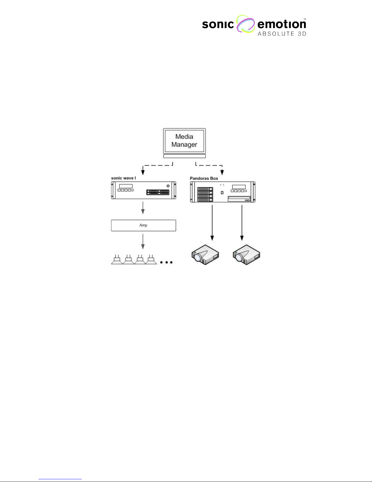
HD Option
The Wave I HD processor option is an additional 24 channel hard disk audio
playback engine, specifically designed to be controlled by the Media Manager show
control software from Coolux Media Systems.
Figure 1.3
Page 10
Page 10 of 72 / Confidential / Version 1.1
Eichweg 6 8154 Oberglatt Switzerland tel +41 (0) 44 850 0838 fax +41 (0) 44 850 0839 pro@sonicemotion.com
www.sonicemotion.com
2. Sonic Wave I Hardware
Connections
ADAT Version
MADI Version
In 1
Out 1
In 2
n 3
Out 3
WC In
WC Out
MADI In
MADI Out
WC In
WC Out
I
WC In
WC Out
In 3
Out 3
In 1
Out 1
In 2
Out 2
In BNC
Out
BNC
Out Opt.
Figure 1.4
Figure 1.5
Page 11
Page 11 of 72 / Confidential / Version 1.1
Eichweg 6 8154 Oberglatt Switzerland tel +41 (0) 44 850 0838 fax +41 (0) 44 850 0839 pro@sonicemotion.com
www.sonicemotion.com
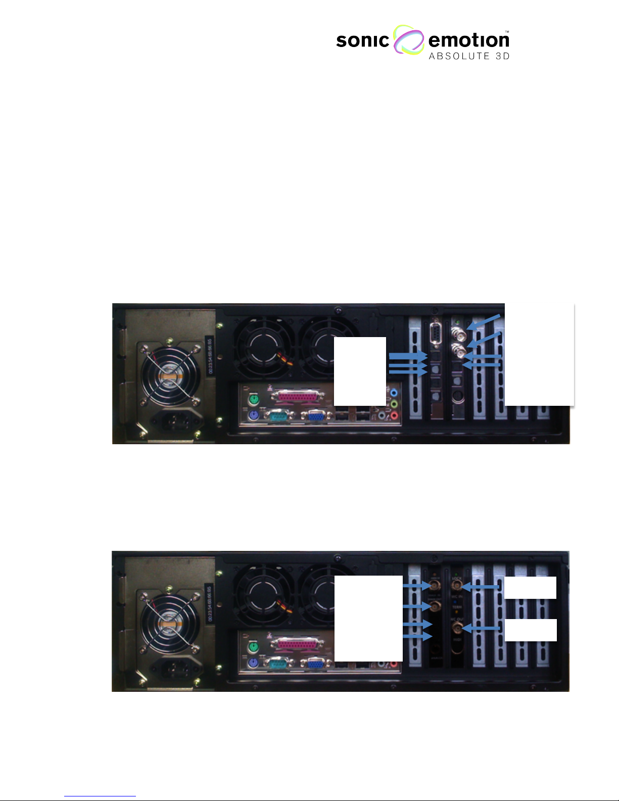
Hardware Revisions
The pictures, Figure 1.4 and 1.5, show the back plate of the Hardware Revision 1
“Pluto”.
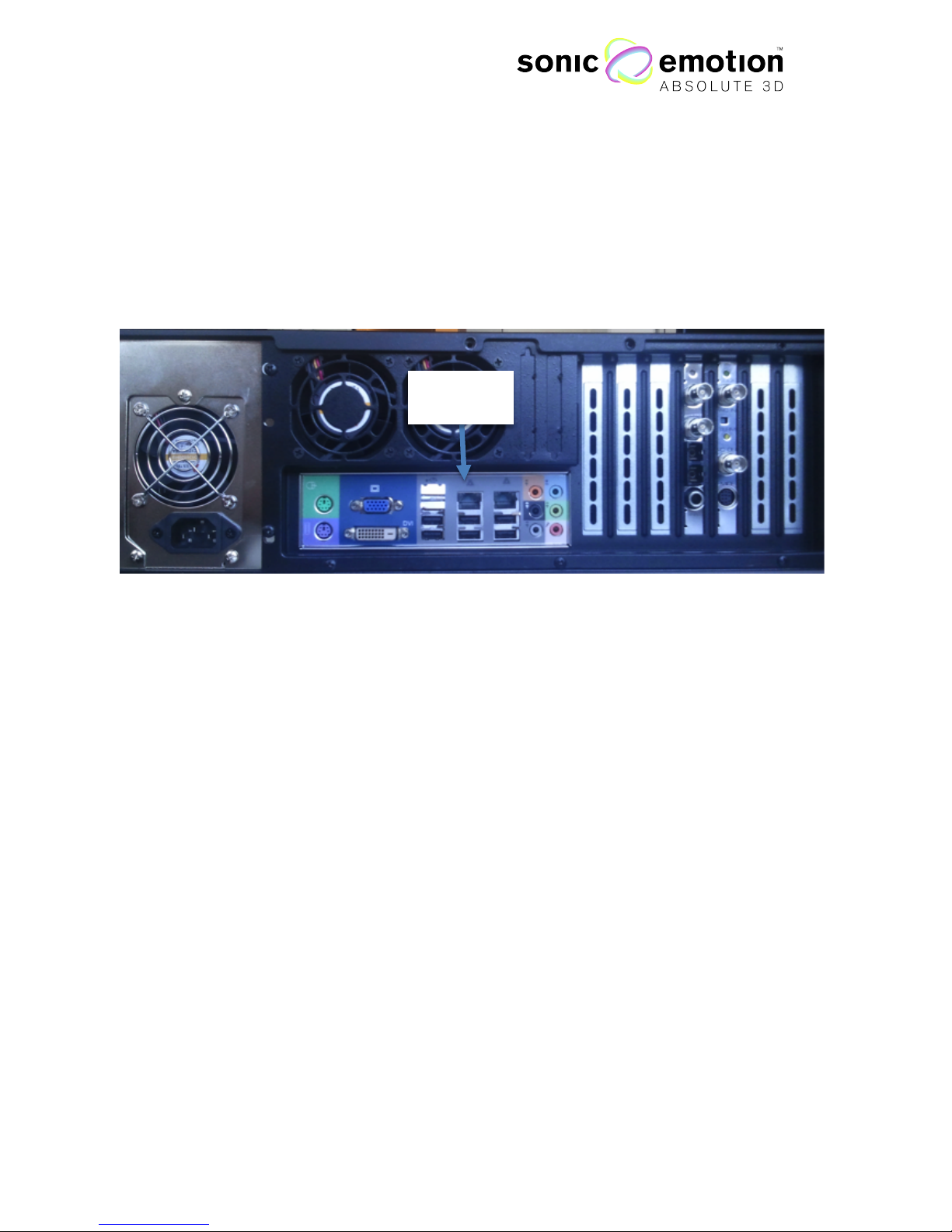
The Hardware Revision 2 “Neptun” of the Sonic Wave I processor comes with two
Ethernet ports. For communication with a control PC the left connector on the
back must be used. See Figure 1.6 below.
System Dongle
The Sonic Wave I processor comes with a system dongle in which all system
specific preferences are stored. The dongle is configured by Sonic Emotion™.
The dongle is processor dependent and only works with the specific Sonic Wave I
processor it is intended for.
It must - at any time - be plugged in in one of the USB port of the Sonic Wave I
processor.
Ethernet
Figure 1.6
Page 12
Page 12 of 72 / Confidential / Version 1.1
Eichweg 6 8154 Oberglatt Switzerland tel +41 (0) 44 850 0838 fax +41 (0) 44 850 0839 pro@sonicemotion.com
www.sonicemotion.com
3. Control Elements
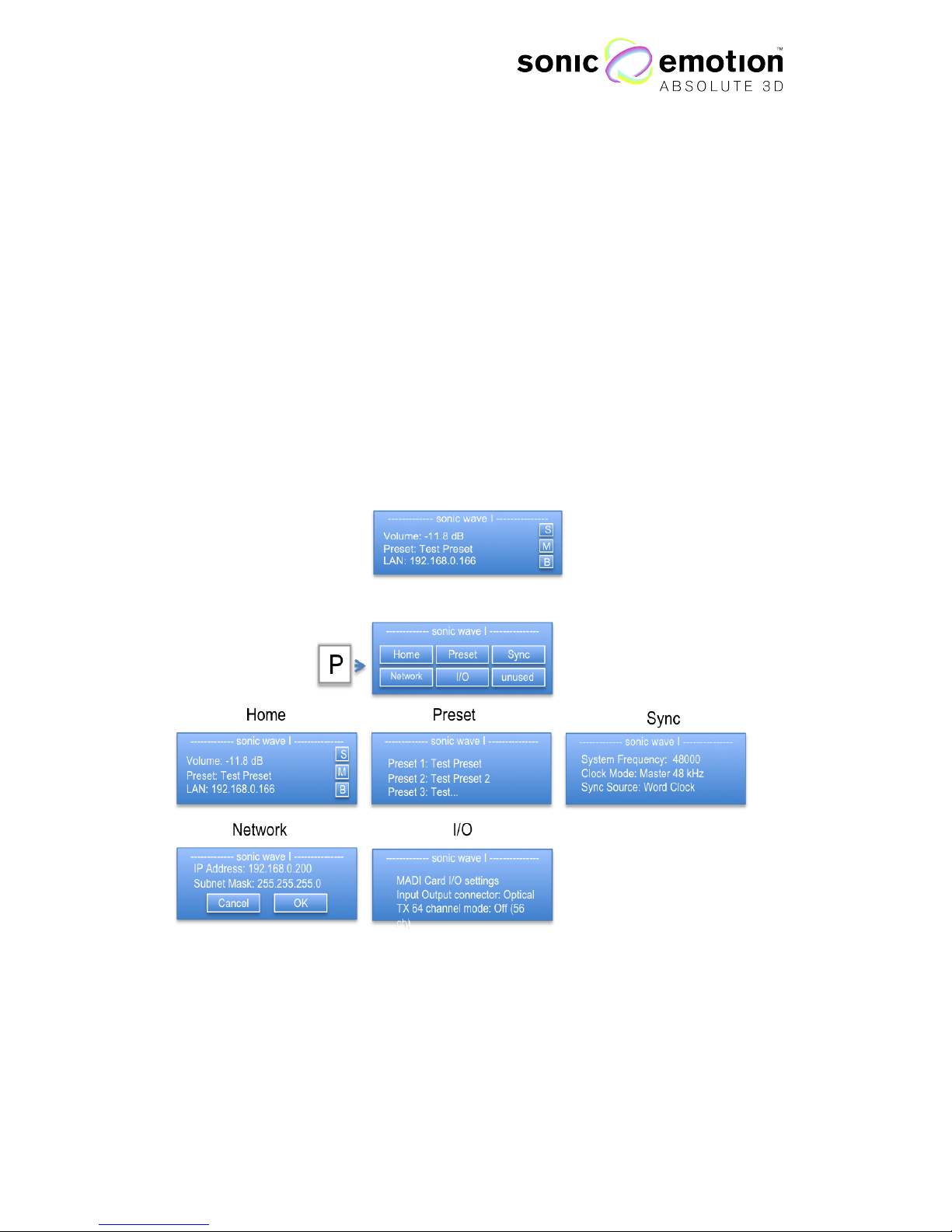
Display Menu
The display menu of the Wave I processor provides access to some of the main
functionalities. The main page is the home window. From the home window, the
encoder adjusts the master volume. The selected source position preset and
network information are displayed. By turning the rotary control on the main page,
you will have direct access to the master volume.
HD Version
On the display home screen, you see if a Coolux Media Manager is connected and
its IP address. The main page contains also information about the usage status of
the storage hard disk used for the audio files and there is an additional menu page
for resetting the disk.
Rotary control
The rotary control next to the display allows you to navigate the menu and change
parameters.
Figure 1.7
Page 13

Page 13 of 72 / Confidential / Version 1.1
Eichweg 6 8154 Oberglatt Switzerland tel +41 (0) 44 850 0838 fax +41 (0) 44 850 0839 pro@sonicemotion.com
www.sonicemotion.com
Buttons
M: Disabled
B: Disabled
P: Preset Menu - Enter the preset menu by pressing P and move through the menu
options by turning the rotary control:
Home: Home window is shown
Preset: The saved presets are shown and can be selected by turning the rotary
control and press enter (E).
IO (only on the MADI version): Press Enter to select between Coaxial or Optical IO
and confirm by pressing Enter again
Network: Use the rotary control and press enter (E) to select and adjust the IP
configuration.
Sync Options: Use rotary control and press enter (E) to select the sync mode and
reference signal for the digital audio interface.
E: Enter
Page 14

Page 14 of 72 / Confidential / Version 1.1
Eichweg 6 8154 Oberglatt Switzerland tel +41 (0) 44 850 0838 fax +41 (0) 44 850 0839 pro@sonicemotion.com
www.sonicemotion.com
4. System Configuration
Software Installation
The Wave I configuration software package (Windows XP & 7) is made to set up
and control your system and create presets. To start the installation process, double
click on the file you will receive per email or downloaded from the Sonic Emotion
FTP Server. Alternatively, insert the Wave I configuration CD into your computer
and start the installation by double clicking on the Wave I configuration icon “config”
(software is part of the system delivery). The installer will put both WaveDesigner for
the system setup and WavePerformer for the control of the system on your PC.
PC Configuration
Before running the applications, the PC network settings must be set-up to enable
the control of the system.
1. The Sonic Wave I processor can be controlled either by a LAN or a WIFI
connection. Make sure the unused connections are disabled.
2. Turn off the firewall
Go to: Start -> Preferences -> Windows Firewall
If you have third party firewalls installed, please make sure that they are
turned off as well.
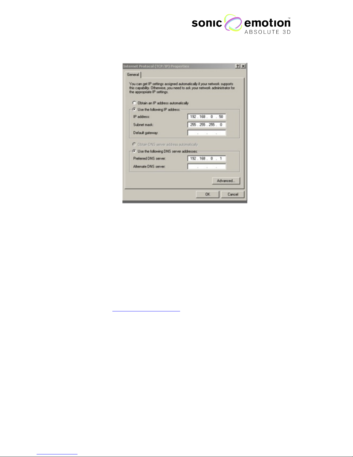
3. Make sure that the IP Address of your PC is set manually and is in the same
range as the Sonic Wave I Processor. By default, the PC can be set to any
IP address 192.168.0.1 – 192.168.0.254, except of 192.168.0.200. Any WIFI
router used must also be in the same IP range.
The default IP address of the Sonic Wave I Processor is 192.168.0.200. It
can be changed on the processors display menu (page 12).
4. The Subnet Mask has to be: 255.255.255.0
Go To: Start -> Connections -> All Connections -> LAN or WLANConnection (regarding what connection you are using)
Then double click “Internet protocol (TCP/IP)”
Page 15
Page 15 of 72 / Confidential / Version 1.1
Eichweg 6 8154 Oberglatt Switzerland tel +41 (0) 44 850 0838 fax +41 (0) 44 850 0839 pro@sonicemotion.com
www.sonicemotion.com
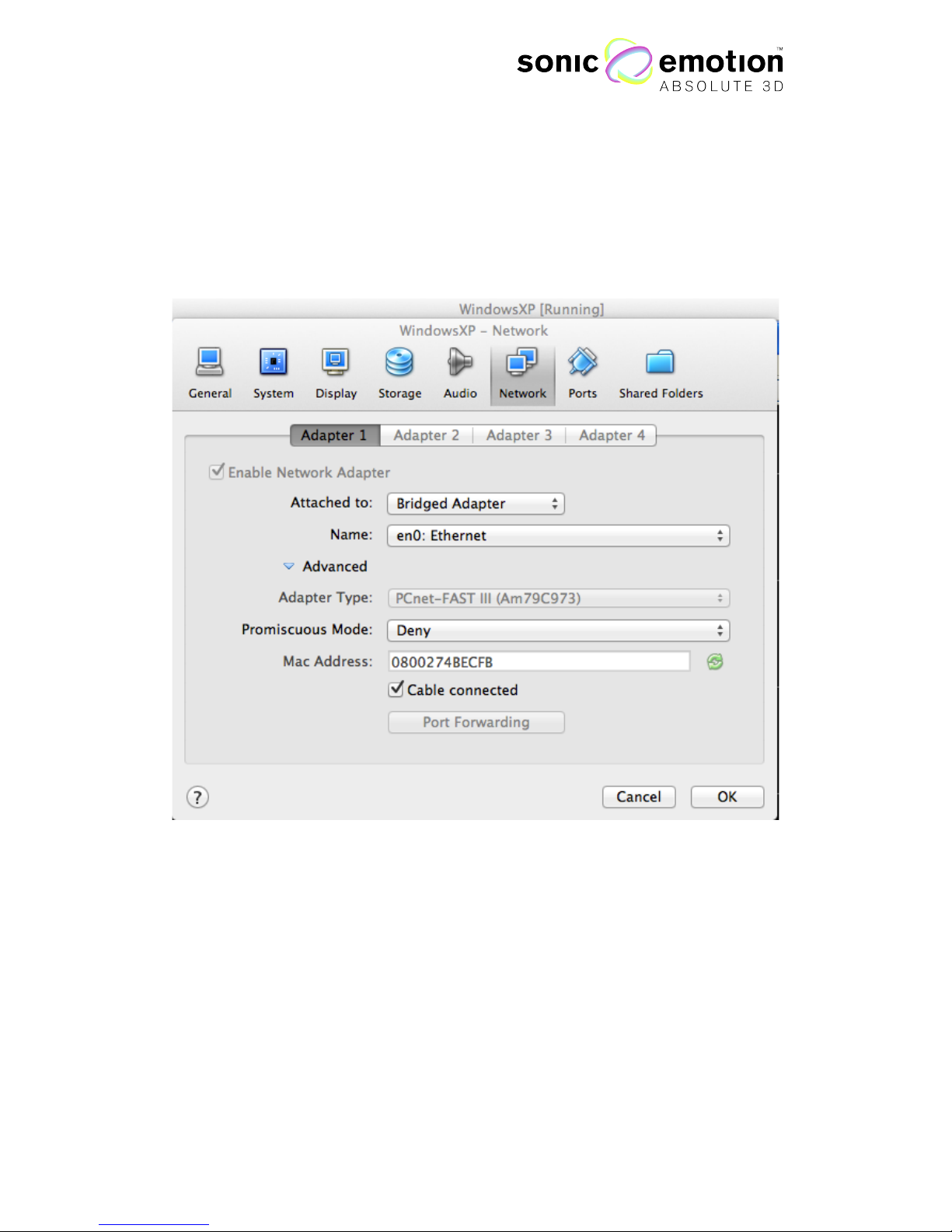
Mac OS X – Setup within Virtual Box
The Mac OS X Version of the Sonic Wave I configuration software package will be
available in the near future. Should this however be your preferred operating system,
you could use virtualization software like VirtualBox to install a virtual Windows
machine on a Mac OS X host. VirtualBox from Oracle is free to use and can be
downloaded from http://www.virtualbox.org
To enable network communication from the virtual Windows machine to a
connected Wave I processor, the following Network settings have to be configured:
Mac OS X (Host):
Set the network adapter that is used for communication with the Wave I processor
to a static IP address in the same range as the processor. The subnet mask must be
set to 255.255.255.0. Make sure to disable wireless if you use a cabled connection
or that there is no other cable plugged if you connect over AirPort. Make sure there
is no firewall active.
Figure 1.8
Page 16
Page 16 of 72 / Confidential / Version 1.1
Eichweg 6 8154 Oberglatt Switzerland tel +41 (0) 44 850 0838 fax +41 (0) 44 850 0839 pro@sonicemotion.com
www.sonicemotion.com
VirtualBox - Network Settings:
Start the Windows machine in VirtualBox. When it is running, go to the VirtualBox
menu bar to Devices -> Network adapters. The following Dialogue will open
up and appear:
Set the attached interface to “Bridged Adapter” and choose to name the device to
which you have configured within Mac OS X to the Wave I processor network
(Ethernet or WLAN/AirPort).
Windows (VirtualBox Guest):
In the running virtual Windows machine, go to the network configuration panel. You
can follow the same instructions for “PC Configuration”. Make sure to set a static
IP-address manually that is different than the one you have assigned in Mac OS X.
For example, the Ethernet port in Mac OS X has the address 192.168.0.50, the
bridged adapter within the virtual Windows 192.168.0.51. Lastly, make sure that the
Windows Firewall is disabled.
Figure 1.9
Page 17

Page 17 of 72 / Confidential / Version 1.1
Eichweg 6 8154 Oberglatt Switzerland tel +41 (0) 44 850 0838 fax +41 (0) 44 850 0839 pro@sonicemotion.com
www.sonicemotion.com
5. Understanding the Functionalities
Essential for a properly working setup is the understanding and application of certain
rules and terms and of how the Sonic Wave I processor handles different types of
speakers. By knowing the following rules, it will give you all the possibilities the
Sonic Wave I processor offers where then mistakes in the configuration of the
processor will inevitably result in an incorrect sound reproduction.
All connected speakers are placed in one or more systems and can be divided into
several subsystems. There are also different rendering types (WFS main, WFS
support and subwoofer speakers) resulting in different spatial rendering modes.
A minimum setup consists of 2 speakers, however for a real exploitation of the Sonic
Wave I processor’s capacity and the WFS rendering, eight or more speakers are
recommended.
More details on setting up speakers can be found on page 67.
Loudspeakers Assignment Hierarchy
System – Sonic Wave I for one listening area
One individual listening area is described as a System. There is always one main
System accounting for the main listening area. An additional System is, for example,
another room, a peripheral / alternative listening area or a production room. Each
System can have its own, individual speakers’ setup. The sound reproduction is
rendered for each System individually referring to its speakers’ setup. To date, the
Sonic Wave I can handle a maximum of 4 Systems processor.
Subsystem
With a Subsystem you can divide the speakers of a System into groups. This is used
for practical and functional reasons:
In windows, such as Speaker Setup and Equalizer you can select a Subsystem, so
that only the speakers belonging to that Subsystem are selectable. When using the
Select All
function, it will then also work to all speakers of the selected Subsystem.
This is a convenient way to access speakers of the same type or same orientation.
Along side a main speaker setup, a supported subsystem is used (WFSmain,
WFSsupport, description follows); each of these setups must be placed in an
individual Subsystem. To date, up to the Sonic Wave I can handle 4 systems
processor.
Page 18

Page 18 of 72 / Confidential / Version 1.1
Eichweg 6 8154 Oberglatt Switzerland tel +41 (0) 44 850 0838 fax +41 (0) 44 850 0839 pro@sonicemotion.com
www.sonicemotion.com
Rendering Types
WFSmain
WFS stands for Wave Field Synthesis and describes the process done by the Sonic
Wave I Processor by rendering the sound sources and reproducing them through
the speakers. There will always be a set of WFSmain speakers. In setups with
several Systems, each System has its individual rendering. All WFSmain speakers in
one System head to one reference point. More details on the reference point are
found in
Speaker Setup
, Page 22.
WFSsupport
WFSsupport speakers are always speakers added to WFSmain speakers, a System
cannot consist of only WFSsupport speakers. The task of WFSsupport speakers is to
enhance or add sound diffusion to a setup of WFSmain Speakers. WFSsupport
speakers are for example:
- Additional delayed speakers further back in a room or under a theatre balcony;
- Additional speakers above a stage that have an array of WFSmain speakers on its
platform edge...others
WFSsupport speakers must be part of an individual Subsystem. The WFSsupport
Subsystem does not include WFSmain speakers.
Subwoofers
Subwoofers are speakers that enhance the reproduction of low end / bass sounds.
When subwoofers are used, the processor uses low-end sound of all sources fed to a
certain speaker within a System or Subsystem. They must be appointed within a set
of WFSmain speakers. Their spatial information is important because they receive a
dedicated spatial rendering to properly align their contribution to the rendering of
the WFSmain speakers.
Summary
A System can consist of one or more Subsystems. A Subsystem can not be shared
among several Systems.
A System contains an array of speakers working as WFSmain; Subwoofers can be
added to the WFSmains.
WFSsupport speakers usually head the same way as the main, front WFSmain
speakers. If placed further back in a room and delayed, they can be heading away
from the reference point.
Page 19

Page 19 of 72 / Confidential / Version 1.1
Eichweg 6 8154 Oberglatt Switzerland tel +41 (0) 44 850 0838 fax +41 (0) 44 850 0839 pro@sonicemotion.com
www.sonicemotion.com
6. The WaveDesigner - Setting-up the
Sonic Wave I Processor
The WaveDesigner software element is a configuration tool to set up the Sonic
Wave I processor for a specific loudspeaker setup. The WaveDesigner sends the
loudspeaker information (position, type, rendering) to the connected Sonic Wave I
processor, which then creates the corresponding filters. Once this step is completed,
the processor is operational and fine-tuning operations can be completed (EQ,
crossover tuning for multiway systems, etc.). All settings can also be saved as a
project file on to your computer.
It is recommended for stability reasons to use the WaveDesigner on a stable
network configuration (private network with the processor, good quality network
cable or excellent WIFI connection).
Workflow
The typical workflow setting up of the Sonic Wave I Processor is done in two
different steps. In the first step, the loudspeaker configuration can be edited and the
output configuration created. Until this step is completed, the processor is
not
operational. Clicking the “Upload” button transfers the configuration to the
processor that creates all the necessary renderings accordingly. The processor can
then be used for real time operation including fine-tuning (loudspeaker EQ, etc.).
The typical workflow of creating a new project with the WaveDesigner can be
described as follows:
1. Configuration according to installation setup
a. Enter the physical position of all loudspeakers used with the processor. A possible
way to measure is to start with the center front speaker and using it as the zero point
on the X, Y axis
b. Adjust loudspeaker type and output assignment
c. Assign rendering type of speakers
d. Allocate speakers to systems and subsystems
e. Upload all above gathered data onto the processor so that it can calculate the filters
2. System fine tuning
a. Test loudspeakers to check if the cabling is right. If not, change cabling or indexes
in Wave Designer and upload data once more
b. EQ processor outputs to match speakers to desired sound color, to adapt different
speaker types in setup and adapt the sound to the room acoustics
c. Store settings to the internal memory of the processor
d. Now, the Sonic Wave I processor is ready to be used and controlled with the
WavePerformer
e. Save the project file on your computer. In case of an unwanted modification of the
processor you can re-upload the project including all settings from your computer
to the Sonic Wave I processor
Page 20

Page 20 of 72 / Confidential / Version 1.1
Eichweg 6 8154 Oberglatt Switzerland tel +41 (0) 44 850 0838 fax +41 (0) 44 850 0839 pro@sonicemotion.com
www.sonicemotion.com
Alternatively, a saved project can be opened in the WaveDesigner. The
configuration should then be transferred to the Processor pressing the upload button.
The processor then calculates first the filters and restarts. All EQ and additional
configuration parameters are then transferred to the Processor. Make sure to store
the configuration on the Processor for next restart.
Page 21
Page 21 of 72 / Confidential / Version 1.1
Eichweg 6 8154 Oberglatt Switzerland tel +41 (0) 44 850 0838 fax +41 (0) 44 850 0839 pro@sonicemotion.com
www.sonicemotion.com
Using the Value Boxes
Many parameters are configured in value boxes. These provide
the possibility to type in values directly, such as: to step up or
down with the spin arrows, or by the mouse wheel when the
mouse pointer is on the corresponding value box. They also
behave like a slider: If pressed with left mouse button on the
arrows and mouse moves up or down, the value increases or
decreases depending on the deflection of the mouse.
How to Store Settings/Save Project Files
When a speaker layout has been set and the Upload button is clicked, the
WaveDesigner software element sends the position data and all settings to the
Sonic Wave I processor, which then calculates the renderings and restarts
automatically.
Changes in speaker positions, rendering, loudspeaker type,
system/subsystems and output assignments will not be calculated real time!
Settings – such as equalizer, gains, delays etc. - are made real-time meaning as
soon as any parameter is modified; this is audible. Select
Store as default
in the
System menu or click the Store button in the upper toolbar to write the settings to
the Sonic Wave I processors internal memory. Storing the parameters does not
require a restart of the processor. If you were to shut down the Sonic Wave I
processor without storing, then all settings that you created in this session will be lost.
In any case, if you choose to shut the processor down or close the WaveDesigner
software, a dialog will appear prompting to choose between storing onto the
processor or saving the project file on your computer.
Figure 1.10
Page 22
Page 22 of 72 / Confidential / Version 1.1
Eichweg 6 8154 Oberglatt Switzerland tel +41 (0) 44 850 0838 fax +41 (0) 44 850 0839 pro@sonicemotion.com
www.sonicemotion.com
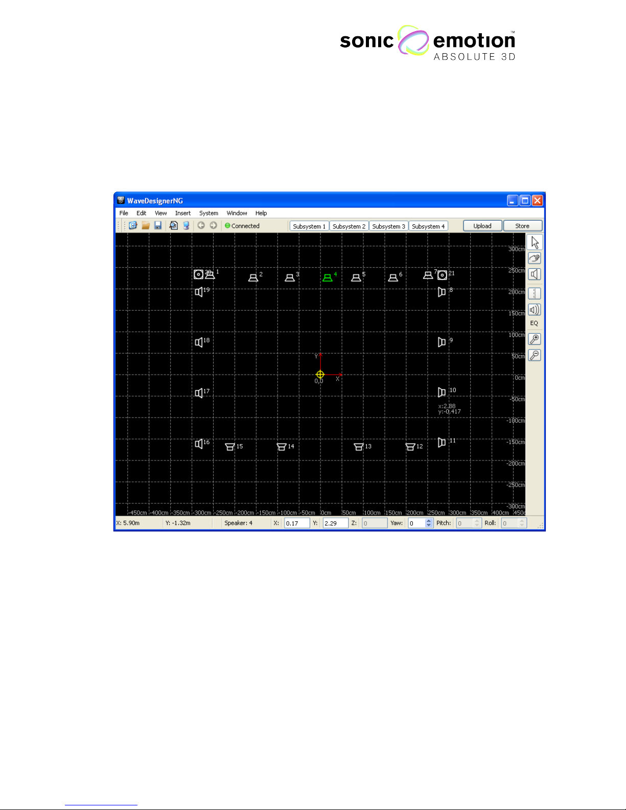
Speaker Setup
After starting the WaveDesigner, the program opens and starts with its main window.
The window can be scaled to a preferred size and also maximized by clicking on the
button in the top right corner.
Loudspeaker placement area:
In the main workspace of WaveDesigner, the speakers can be freely placed and
moved around by drag & drop. The fixed zero point of the drawing area is displayed
with red arrows for the X and Y dimension. All speaker positions are displayed in
relation to this zero point. To make loudspeaker placement more convenient, a grid
is plotted on the workspace to show the actual dimensions of the displayed area.
The grid scales automatically on zooming and can be disabled in the view menu
(page 24).
Figure 1.11
Page 23

Page 23 of 72 / Confidential / Version 1.1
Eichweg 6 8154 Oberglatt Switzerland tel +41 (0) 44 850 0838 fax +41 (0) 44 850 0839 pro@sonicemotion.com
www.sonicemotion.com
Loudspeakers icons:
The loudspeakers are represented as figurative icons that will always remain
the same size, independent of the zooming factor. If a speaker is selected, it
appears in green color, otherwise it appears in white.
Subwoofers are displayed with a different icon. Each speaker in the setup is
displayed with its given index at the right top. This behavior can be disabled in the
view menu.
If the mouse pointer is moved over a speaker, the current position is displayed as a
hover effect.
New loudspeakers can be added to the grid either through mouse click on the
desired position (if in speaker add mode), with the loudspeaker array dialog or
through the insert menu.
Right clicking on the speaker icon opens a dialog to choose
Delete Speaker, Speaker Management (page 32), and
Equalizer (page 34).
Reference Point:
An important element of the loudspeaker setup is the
Reference Point. When the loudspeaker positions are
transmitted to the Wave I processor to create the
corresponding filters (upload), all speaker positions are
translated into a coordinate system according this Reference
Point. Therefore, the Reference Point should be located
within your loudspeaker setup. The Reference Point is also the
origin point for placing virtual sound sources when filter generation is completed
(see also WavePerformer, page 38).
The Reference Point is displayed as a yellow crosshair. Its default position is the zero
point of the drawing coordinate system for when WaveDesigner is started. The
Reference Point can be moved freely with drag & drop or set automatically to a
position within the setup. In the Edit menu, there is the option “Reference Point“ to
reset it to the zero origin or to calculate an optimal position.
Warning: For the system to optimally operate, the reference point must be located
inside the listening area and all speakers of WFSmain rendering type must face the
reference point. If not, the rendering will fail.
Figure 1.12
Figure 1.13
Page 24

Page 24 of 72 / Confidential / Version 1.1
Eichweg 6 8154 Oberglatt Switzerland tel +41 (0) 44 850 0838 fax +41 (0) 44 850 0839 pro@sonicemotion.com
www.sonicemotion.com
Control Elements
Menu Bar
As found in other common PC applications, the WaveDesigner includes a menu bar
on top of the program window. Most menu options are accessible through keyboard
shortcuts; these are displayed beside the menu entries. Following options are
present in the WaveDesigner menu bar:
File Menu:
On the file menu, you can start a new project (
New
), open a saved project (
Open
)
and save the current setup (
Save As
). In the project file, all speaker related
information is stored: The position data, output setting, EQ settings and subsystem
settings.
The Import option allows reading back an existing loudspeaker configuration from a
connected Sonic Wave I Processor (
from Processor
) or import a loudspeaker
definition file in the old format from config tool version 1. (
From File
). Please note
that in the old txt-file (typically lsdefinition.txt) no EQ settings are stored. It is only
provided for backward compatibility to the config tool version 1.
Project Files in xml format from WaveDesigner version 2 can be loaded through the
file open dialog. However, only position data and EQ parameters from V2 are
imported (5 band EQ, no shelving filters, no subsystem or output splitting).
Print preview
and
Print
give the possibility to preview and print a loudspeaker setup.
Quit
closes the application. However, a dialog always appears first, asking if you
want to save the current status beforehand.
Edit Menu:
WaveDesigner has full undo and redo capabilities, both are accessible in the Edit
Menu.
The
Reference Point
option allows to reset the Reference Point to the zero point of
the loudspeaker area or to automatically compute a position within the given
speaker setup.
Sort Speakers
opens a dialog that gives the possibility to sort the loudspeakers by
automatically reassigning loudspeaker indices. The sort algorithm can be applied
clockwise or counter clockwise and the first speaker can be defined. All speakers are
given indices in ascending order starting from the position of speaker 1. The
algorithm first calculates the angle of each loudspeaker according to the reference
point and reassigns loudspeaker indices according to the specified options.
Figure 1.14
Page 25

Page 25 of 72 / Confidential / Version 1.1
Eichweg 6 8154 Oberglatt Switzerland tel +41 (0) 44 850 0838 fax +41 (0) 44 850 0839 pro@sonicemotion.com
www.sonicemotion.com
View Menu:
Display Grid
turns on and off the grid on the workspace. If enabled, there is a
checkmark besides the menu entry.
Display Index
toggles on and off the display of the Index besides the loudspeaker
icons.
Show Toolbar
allows to show / remove the right toolbar to gain more space for the
loudspeaker placement area.
Insert Menu:
Add Speaker
opens a dialog to add one speaker to the workspace and set all
parameters at once. The loudspeaker will be added at the specified position after
hitting the OK button.
Add Array
opens a dialog to add an array of speakers to the workspace. The array
can be shaped as a line or in a circular shape. To add an array, the number of
speakers, length, center point and orientation of the line or radius, start and end
angle of a circular array have to be specified. On OK, the array will be added to the
grid. All positions are meant relative to the 0,0 point.
Processor:
In the processor menu, you can shutdown the Sonic Wave I processor if connected,
and collect system info.
You can also
Store default values
: Settings such as equalizer, gains, delays etc. are
made real-time meaning as soon as any parameter is modified, this is audible.
Select
Store as default
in the System menu or click the Store button in the upper
toolbar to write the settings to the Sonic Wave I processors internal memory. Storing
these parameters does not require a restart of the Processor. If the Sonic Wave I
processor is shut down without storing, all settings you have done in this session will
be lost. In any case, if you choose to shut the Processor down or close the
WaveDesigner software, then a dialog will appear asking you if you want to store to
the Processor or also save to the project file on your computer.
Window:
Open the dialog windows for Subsystem Control (page 33), Equalizer (page 34) and
Speaker Management (page 37) and Output Assignment (page 38)
Help Menu:
The help menu shows the
about
box that tells you the current software version.
Page 26

Page 26 of 72 / Confidential / Version 1.1
Eichweg 6 8154 Oberglatt Switzerland tel +41 (0) 44 850 0838 fax +41 (0) 44 850 0839 pro@sonicemotion.com
www.sonicemotion.com
Upper Tool Bar
The upper toolbar of WaveDesigner gives quick access to some of the
functionalities that are also present in the menu bar. These are New, Open, Save,
Print preview, Print, Undo and Redo.
Following this step is an Indicator showing if WaveDesigner is connected to a Wave
I processor. If connected, the dot is green, if not, red. The display changes
automatically if you connect or disconnect the network connection to the Processor.
The four Subsystem tabs enables you to view/hide the speakers of the associated
subsystem.
Upload:
On the right hand side of the upper tool bar is the Upload button. This is a very
important element of WaveDesigner. Pressing the upload button sends the defined
loudspeaker setup (positions, speaker properties, output assignment) to the Sonic
Wave I processor witch then calculates the renderings. After uploading, the
processor is restarting automatically and online parameters that may have been
loaded from a previous project are transferred to the processor (speaker
management, eq’s, delays, etc.).
Changing the speaker positions cannot be calculated real time! For each change,
the processor is restarting after parameter calculation. The process and success of
creating the filters is reported by a dialog.
Before the definition file is uploaded, several checks are done to prevent unexpected
behavior. If one of the following conditions fails, an error message is displayed:
• Connection: There has to be a network connection to the processor.
• Number of speakers: At least 2 speakers have to be present to enable 3D sound rendering.
There is also a maximum number of speakers that can be used with a Sonic Wave I
processor corresponding to its number of output channels (mostly 24 or 32).
• All WFS main speakers have to be faced towards the Reference Point.
• A Subsystem can only include either WFSmain or WFSsupport speakers.
• Each index number can only be present once in the loudspeaker setup.
• A physical output can only be used once.
Figure 1.15
Page 27

Page 27 of 72 / Confidential / Version 1.1
Eichweg 6 8154 Oberglatt Switzerland tel +41 (0) 44 850 0838 fax +41 (0) 44 850 0839 pro@sonicemotion.com
www.sonicemotion.com
Store:
This button has the same function as
Store default values
in the Processor Menu in
the Menu bar: Settings like equalizer, gains, delays etc. are made real-time
meaning as soon as any parameter is modified, this is audible. Select
Store as
default
in the Processor menu or click the Store button in the upper toolbar to write
the settings to the Sonic Wave I processors internal memory. Storing these
parameters does not require a restart of the processor. If the Sonic Wave I processor
is shut down without storing, all settings you have done in this session will be lost. In
any case, if you choose to shut the Processor down or close the WaveDesigner
software a dialog will appear asking you if you want to store to the Processor or also
store to the project file on your computer.
Right Tool Bar
On top of the right-hand tool bar, there are three buttons to toggle the different
operation modes of WaveDesigner.
Selection mode:
In this mode, speakers can be selected by mouse click and moved around.
With right mouse click, a context menu can be opened to delete this speaker,
open its properties dialog or to open the EQ panel for that speaker.
If a speaker is selected, it can be deleted with the delete key. Several
speakers can be selected by pressing control key and clicking them or by
defining a rubber band area around them with pressed left mouse button.
Navigation mode:
This mode is simply for navigating in the workspace. When enabled, the
mouse pointer changes to a hand icon. No elements in the workspace can
be selected or moved. Tip: you can also navigate by pressing the middle
mouse button.
Speaker Add mode:
In Speaker Add mode, loudspeakers can be added to the workspace by
clicking the left mouse button. When enabled, the mouse pointer
changes to a cross to allow precise positioning.
Figure 1.16
Page 28

Page 28 of 72 / Confidential / Version 1.1
Eichweg 6 8154 Oberglatt Switzerland tel +41 (0) 44 850 0838 fax +41 (0) 44 850 0839 pro@sonicemotion.com
www.sonicemotion.com
Add Speaker Array
and
Test tool
. These tools are described on page 28 and
30.
Zoom:
On the lower side, there are buttons for zooming in and zooming out the workspace.
Tip: you can zoom in and out with a mouse wheel.
Add Array Dialog
Linear Array:
With the Linear Array option, the speakers are aligned in a
straight line. The number of speakers, the overall length of the
line and the coordinates of its center point can be defined.
Orientation sets the orientation of the loudspeaker array.
In a loudspeaker setup where speakers are mounted to the walls
of a room with even distance, the Array Dialog gives an easy
way to define the setup for the Sonic Wave I processor.
All values are referenced to the 0,0 point.
Circular Array:
The Circular Array option gives the possibility to add multiple
speakers in a circular alignment. There are controls to set the
number of speakers, the radius of the circle, center point
coordinates and start and end angle of a section.
In this way, loudspeakers can be automatically aligned either as full circle or only as
an arbitrary portion defined through start and end angle.
All values are referenced to the 0,0 point. Angle 0 is given towards the Y positive
axis in counter clockwise order.
Figure 1.17
Page 29

Page 29 of 72 / Confidential / Version 1.1
Eichweg 6 8154 Oberglatt Switzerland tel +41 (0) 44 850 0838 fax +41 (0) 44 850 0839 pro@sonicemotion.com
www.sonicemotion.com
Status Bar
The Status Bar underneath the main loudspeaker placement area shows some
useful information about the position grid. On the left side, the current mouse
position is displayed as X and Y coordinates in meters. When a speaker is selected
by clicking, the properties of that speaker are displayed on the right side (Index, X, Y,
Z, Yaw, Pitch, Roll).
The X, Y and Yaw parameters can directly be edited in the status bar by entering
new values or hitting the arrows for the Yaw spin box. If multiple speakers are
selected, the difference of old and new value is applied as an offset to all selected
speakers.
The Z, Pitch and Roll options are disabled. They will be enabled in future versions of
the software.
Figure 1.18
Page 30

Page 30 of 72 / Confidential / Version 1.1
Eichweg 6 8154 Oberglatt Switzerland tel +41 (0) 44 850 0838 fax +41 (0) 44 850 0839 pro@sonicemotion.com
www.sonicemotion.com
Output Assignment
This window can be opened in the menu bar: Window – Output Assignment. Each
speaker in the setup has certain settings as already seen in the Speaker
Management. Additionally in this window, the speakers can be distributed into
Systems, Subsystems, Rendering type (these are explained on page 16), and for the
active crossover the output channel can be selected. Seen in Figure 1.19
Speaker
The speakers are numbered; these numbers correspond to the Index number shown
on the main window. The checkbox turns the speaker on or off, removing or adding
it to the configuration for filter calculation.
System / Subsystem / Rendering
Each speaker belongs to a System, Subsystem and has a certain rendering type.
These settings are explained on page 16.
In case of multi-amplified speakers, the settings can be as follows: You can select
“two way” or “three way” if the connected speaker is active. The following pull-down
Figure 1.19
Page 31

Page 31 of 72 / Confidential / Version 1.1
Eichweg 6 8154 Oberglatt Switzerland tel +41 (0) 44 850 0838 fax +41 (0) 44 850 0839 pro@sonicemotion.com
www.sonicemotion.com
menus select the physical outputs to use. Additional settings like crossover
frequencies, level, delay, limiter, polarity etc. are accounted for in the Speaker
Management window (page 33).
Eventually the amplifier power and sensitivity is set. This is important so that the
Sonic Wave I processor can deliver the same output level to the speakers, as well as
when different kind of speakers are connected.
Page 32

Page 32 of 72 / Confidential / Version 1.1
Eichweg 6 8154 Oberglatt Switzerland tel +41 (0) 44 850 0838 fax +41 (0) 44 850 0839 pro@sonicemotion.com
www.sonicemotion.com
Upload configuration
Pressing the “Upload” button transfers the configuration to the processor. The
processor then calculates the renderings and gets configured according to the
defined configuration. Once the filter calculation is done, loudspeaker positions and
all parameters for the output assignment window should not be modified unless
uploading again the configuration.
Test Tool
The test tool provides a line-check to test the cabling of the
Wave I processor to the loudspeakers. It can be opened through
the symbol button in the right tool bar.
When starting the General Test, the Sonic Wave I processor
automatically iterates through all configured outputs assigned in
WaveDesigner. It connects the chosen input to all speakers
starting from the first one and plays the given input signal for a
few seconds on each speaker. The current active speaker
changes its color to blue in the workspace. If Individual Test is enabled, only the
selected loudspeakers in the workspace are used for the loudspeaker test. The
volume of can be changed during test with the slider.
Cancel
stops the running test and sets the Sonic Wave I processor back into normal
operation mode with the current filter set and routing.
Figure 1.20
Page 33

Page 33 of 72 / Confidential / Version 1.1
Eichweg 6 8154 Oberglatt Switzerland tel +41 (0) 44 850 0838 fax +41 (0) 44 850 0839 pro@sonicemotion.com
www.sonicemotion.com
Subsystem Control
From the Window tab in the Menu bar the
Subsystem Control is opened. Here the Subsystems
can be labeled. All speakers belonging to a
Subsystem can be adjusted in gain and delay. These
parameters are added to parameters done
individually to the speakers in that Subsystem. They
allow for adjusting subsystems among each other.
The usage of Subsystem is explained on page 16.
Speakers are added to Subsystems in the Output
Assignment window explained on page 38.
Figure 1.21
Page 34

Page 34 of 72 / Confidential / Version 1.1
Eichweg 6 8154 Oberglatt Switzerland tel +41 (0) 44 850 0838 fax +41 (0) 44 850 0839 pro@sonicemotion.com
www.sonicemotion.com
Equalizer
Each output or speaker has its dedicated parametric equalizer. When
in Selection Mode (page 27), Equalizer dialog can be opened via the
context menu by right clicking the speaker. This window can also be
opened in the menu bar: Window – Equalizer or through the button in
the toolbar labeled “EQ”.
The main area of the EQ panel shows a plot of the frequency response for the
selected speaker.
On the left side is a control box for general options:
Speaker Selection:
This section has two dropdown boxes for selecting the speakers.
The first dropdown box allows selecting a specific subsystem or all subsystems at
once.
The second dropdown box provides a limited list of speakers identified by their index.
This list corresponds to the selected subsystem or all speakers if “all” is selected in
the first dropdown box. Selecting a speaker retrieves the corresponding EQ controls
from the Sonic Wave I processor or the local status if a Sonic Wave I is not
connected. The user can then modify these settings interactively.
Figure 1.22
Page 35

Page 35 of 72 / Confidential / Version 1.1
Eichweg 6 8154 Oberglatt Switzerland tel +41 (0) 44 850 0838 fax +41 (0) 44 850 0839 pro@sonicemotion.com
www.sonicemotion.com
Control All:
If the checkbox is enabled, the current EQ settings are sent to either all speakers of
the selected subsystem or all speakers of the setup depending on the settings of the
first dropdown menu. A warning popup window appears and allows cancelling the
action. All following changes are also applied to the selected speaker list. The
speaker index or the selected subsystem is also indicated in the upper left corner of
the Parametric EQ panel giving feedback to the user on what is currently controlled.
The makeup gain remains individual to each speaker and is not affected by the
control all setting.
Test Mode:
If this checkbox is enabled, the signal of the selected input is directly routed to the
speaker selected in the control area. This way each speaker can be listened to and
equalized separately. The input can be selected with the corresponding dropdown
menu.
Volume:
This slider controls the master volume of the Sonic Wave I processor. This controller
corresponds to the volume control on the WavePerformer Main Window.
Copy/Paste:
The copy button takes a snapshot of the current EQ settings. It enables the user to
switch to another speaker and apply these settings with the Paste button.
Reset:
Reset flattens the EQ curve of the current speaker or the selected list of speakers
when Control All is active.
Bypass:
The Bypass button switches on or off the EQ on the Sonic Wave I processor. The
current state is indicated through a green or red LED.
Page 36

Page 36 of 72 / Confidential / Version 1.1
Eichweg 6 8154 Oberglatt Switzerland tel +41 (0) 44 850 0838 fax +41 (0) 44 850 0839 pro@sonicemotion.com
www.sonicemotion.com
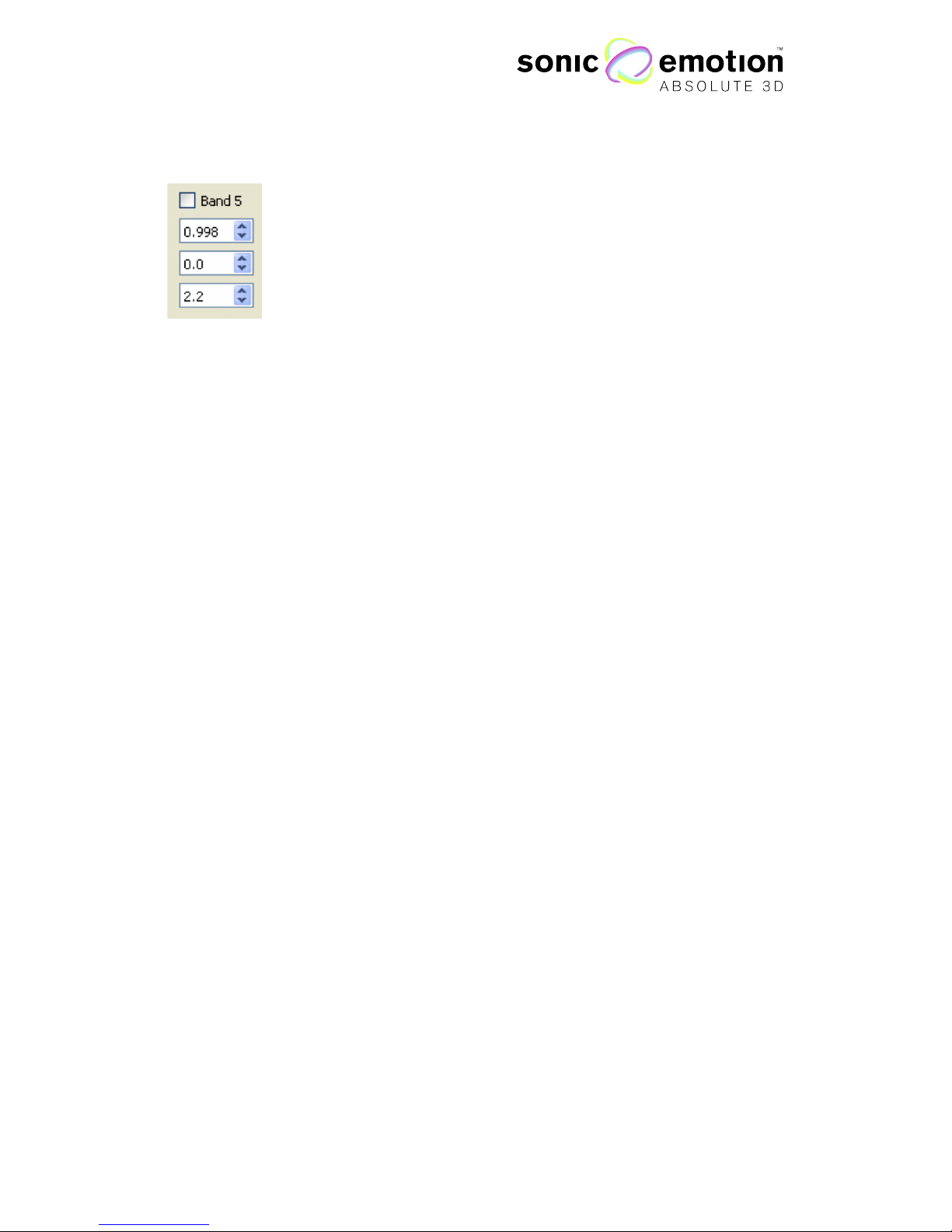
The Sonic Wave I processor offers equalizers with 8 fully parametric bell filters, high
and low shelving filters and a high pass and low pass filter. All EQ related controls
are grouped together in the Parametric EQ box.
High Pass / Low Pass
The High pass and Low pass filters can be switched on with the checkbox. The
frequency spin box controls the frequency where the filter is applied. The slope
adjusted in steps in a dropdown menu.
Makeup Gain:
On the right side of the response plot, there is a slider for a general makeup gain.
This control always operates on one speaker only. The corresponding speaker index
is indicated on the lower part of the panel. Its main use is for level adjustment when
dissimilar loudspeakers are used in the setup or exhibit slightly different levels after
EQ.
Page 37

Page 37 of 72 / Confidential / Version 1.1
Eichweg 6 8154 Oberglatt Switzerland tel +41 (0) 44 850 0838 fax +41 (0) 44 850 0839 pro@sonicemotion.com
www.sonicemotion.com
Speaker Management
When in Selection Mode (page 27), a Speaker Management dialog
can be opened via the context menu by right clicking the speaker. This
window can also be opened in the menu bar: Window – Speaker
Management.
Here you can define your speaker as being treated as a passive speaker using its
own processing or you can create an own crossover to feed a multi-way speaker
directly from the Sonic Wave I Processor. Also you can adjust output gain for each
way, invert phase (polarity) and use a limiter.
Subsystem:
With a subsystem chosen here, the speaker selection
in the next drop box is filtered to the members of the
selected subsystem. Select
all
to make all speakers
viewable.
Speaker Selection:
This dropdown box has entries for all speakers in the setup identified by their index.
If a speaker is selected, the corresponding output setting controls are read from the
Sonic Wave I Processor and can be modified by the user interactively.
Crossover:
You have the choice of using a full range (passive) speaker or 2 to 3 way speaker
systems using dedicated outputs of the Sonic Wave I processor. Select type of
speaker, turn on the crossover with the checkbox and enter the corner frequencies
of each way. This parameter is directly taken into account if a Sonic Wave I
processor is connected.
Low / Mid / High:
Every crossover output has their own gain, can invert phase (polarity) and has an
own peak limiter. Amplifier power and sensitivity, and physical output each way are
selected in the Output Assignment window (page 38).
Figure 1.23
Page 38

Page 38 of 72 / Confidential / Version 1.1
Eichweg 6 8154 Oberglatt Switzerland tel +41 (0) 44 850 0838 fax +41 (0) 44 850 0839 pro@sonicemotion.com
www.sonicemotion.com
8. Control the Sonic Wave I Processor
with WavePerformer
WavePerformer is an application, which provides an easy and intuitive way to
interactively control the sound field while using the Sonic Wave I processor. Once
you have created and uploaded filters for your loudspeaker-setup in the
WaveDesigner (page 16), you can define the position of virtual sound sources while
playing them back on your setup. The Source Positioning window shows a
positioning area where all or selected sound sources are displayed. Each sound
source represents one input channel. Sound source 1 corresponds to the first
physical input channel, sound source 2 to the second one, etc.
The system reproduces the current sound position in real-time. Depending on the
distance from the listening area, the sound wave characteristics change. Sound
sources that are close to the listening area are played back at its focused position.
With increasing distance from the reference point, the sound wave becomes more
plane and is heard from the same direction (angle) in the entire room, allowing a
sweet spot free playback of surround sound. In addition, if distance attenuation
(page 43) is selected, the volume is decreasing with increasing distance from the
reference point.
The WavePerformer also allows basic diagnostic tools for the Sonic Wave I
processor (running, momentary input level, IP address, HD status, sync setting). In
the Level Tab the levels for all 24 input channels can be set and also be muted.
The current positions and levels for all sources can be stored as a static pre-set
which can be recalled through the WavePerformer or also on the display of the
processor itself.
Using the Value Boxes
Many parameters are configured in value boxes. These provide the
possibility to type in values directly, to step up or down with the spin
arrows, or by the mouse wheel when the mouse pointer is on the
corresponding value box and they also behave like a slider. If pressed
with left mouse button on the arrows and mouse moved up or down,
the value increases or decreases dependent on the deflection of the
Figure 1.24
Page 39

Page 39 of 72 / Confidential / Version 1.1
Eichweg 6 8154 Oberglatt Switzerland tel +41 (0) 44 850 0838 fax +41 (0) 44 850 0839 pro@sonicemotion.com
www.sonicemotion.com
mouse. Each band can be enabled with the checkbox above its parameters.
Note: The WavePerformer can only be used when the speakers
connected to the Sonic Wave I p rocessor have been setup using the
WaveDesigner software.
Control Elements
Menu bar
File Menu:
The file Menu gives you the possibility to load and save presets from the preset list
and manually Import a layout from the processor or from a file. Furthermore, here
you can quit the WavePerformer application.
Processor:
In the processor menu, with Save Default Preset you can save the currently open
layout as the default preset. This is then the state the Sonic Wave I processor will be
in when it is powered up.
Shutdown will turn of the Sonic Wave I processor.
View:
Display Grid turns on and off the grid on the workspace. If enabled, there is a
checkmark besides the menu entry. Display Index toggles on and off the display of
the Index besides the loudspeaker. Clip Distance selects the behavior after the
maximum distance (page 30). Show Toolbar allows to remove the right toolbar to
gain more space fort he loudspeaker placement area.
Help Menu:
The help menu show the about box that tells you about the software version.
Figure 1.25
Page 40

Page 40 of 72 / Confidential / Version 1.1
Eichweg 6 8154 Oberglatt Switzerland tel +41 (0) 44 850 0838 fax +41 (0) 44 850 0839 pro@sonicemotion.com
www.sonicemotion.com
Upper Tool Bar
Preset Control:
The Preset Control allows saving and loading different source setups. The data
included into a preset are: Source positioning, input levels, activation of distance
attenuator and equalizer settings. Not included are sync settings. If you want a
certain preset to be the default preset of the Sonic Wave I processor, there is an
option in the file menu system->save default preset. After booting up the
WaveProcessor, it will be set to this state.
To save a static sound source set up, place the sound sources to the desired
positions and control the levels, edit the name of the preset in the top left menu and
then click on the save button. The preset will now be available on the Sonic Wave I
processor and can be selected with its name in the preset menu on the display.
Source Groups:
Right above the main source are 6 toggle buttons to control which sources should
be displayed on the panel. You can select which groups are shown (sources 1-4, 5-8,
9-12, 13-16, 17-20, 21-24) or select all sources.
Left Tabs
With the tabs on the right side of the window, you can choose between the
Source Positioning panel, the Input selection panel, the Routing panel, the
EQ panel and the Sync panel. These panels are described further down
(page 42).
Figure 1.26
Figure 1.27
Page 41

Page 41 of 72 / Confidential / Version 1.1
Eichweg 6 8154 Oberglatt Switzerland tel +41 (0) 44 850 0838 fax +41 (0) 44 850 0839 pro@sonicemotion.com
www.sonicemotion.com
Right Tool Bar
Zoom:
On the topside are buttons for zooming in and zooming out the workspace.
Tip: You can zoom in and out with a mouse wheel.
Volume:
Here you can adjust the overall system volume. This controller corresponds
to the volume control on the WaveDesigner Equalizer window.
Mute:
Mutes all outputs.
Status Bar
The Status Bar underneath the main area shows some useful information about the
position grid. On the left side, the current mouse position is displayed as X and Y
coordinates in meters. When source is selected by clicking, the properties of that
source are displayed on the right side (Index, X, Y, Z, Angle, Distance).
The X, Y, angle and distance parameters can directly be edited in the status bar by
entering new values. If multiple sources are selected, the difference of old and new
value is applied as an offset to all selected speakers in Cartesian (X, Y) coordinates.
The Z option is disabled. It will be enabled in future versions of the software.
In Preset Status, you can see what preset is currently loaded.
Figure 1.28
Figure 1.29
Page 42

Page 42 of 72 / Confidential / Version 1.1
Eichweg 6 8154 Oberglatt Switzerland tel +41 (0) 44 850 0838 fax +41 (0) 44 850 0839 pro@sonicemotion.com
www.sonicemotion.com
Source Positioning Panel
The main part of the workspace shows the Source Positioning. In its center is the
loudspeaker setup that the Sonic Wave I processor is currently configured for. If you
are connected to a processor, the loudspeaker setup and all source values are
automatically downloaded from the system. You can also manually import the
speaker setup in the Menu with “File->Import from system” or from a locally stored
lsdefinition.txt through the “File->Import from file” option.
Sources can be grabbed with a mouse click and dragged around. The current
position values of the selected source are also displayed in the status bar underneath
the source area.
A specific source can also be quickly selected via keyboard short cut “ctrl+1” –
“ctrl+0” for sources 1-10 and “alt+1” – “alt+6” for sources 11 - .20
Figure 1.30
Page 43

Page 43 of 72 / Confidential / Version 1.1
Eichweg 6 8154 Oberglatt Switzerland tel +41 (0) 44 850 0838 fax +41 (0) 44 850 0839 pro@sonicemotion.com
www.sonicemotion.com
The inner dashed circle in the source placement area represents the distance at
which the level attenuation starts (0 dB distance). If Distance Attenuation is enabled
in the Level Panel, the level decreases when a source is moved further away and
gives a natural feeling of increasing distance.
If the mouse pointer is moved over a virtual source, its current angle
and distance position is displayed with a hover effect.
Maximum Source Distance:
The ring within the source placement area visualizes the maximum distance from
the center of which sources can be placed. If sources are moved outside this ring,
they are clipped. The maximum distance is depending on the loudspeaker setup
and corresponds to the maximum source distance in the current filter set on a
connected Processor. Above this distance, virtual source rendering is kept constant
except for distance relative volume attenuation. The clipping at setup dependent
distance can be disabled in the view menu (page 24), so sources can be moved
within the full range of distance up to 200 m.
Multiple Select:
It is possible to select several sources at the same time and move
them as a group, so they will keep their relative positions to each
other. To select multiple sources, draw a rectangle with a mouse
around the sources to group, select them manually with pressing
ctrl-key while clicking them or use the keyboard shortcuts for group
selection (ctrl-key + number or alt-key + number, see above).
If multiple sources are selected, they appear with a cyan circle around them. The
master source for moving is marked with a red circle; also the values in the status
bar correspond to this master source. The master is simply selected by clicking on
one of the selected sources. The group can thus be moved by keeping left clicked
source down and move the mouse pointer into the workspace.
Input Panel
The input panel gives you direct access to the level control and source of all 24 input
channels. There is a horizontal scroll bar on the lower end of the panel to access all
Figure 1.31
Figure 1.32
Page 44

Page 44 of 72 / Confidential / Version 1.1
Eichweg 6 8154 Oberglatt Switzerland tel +41 (0) 44 850 0838 fax +41 (0) 44 850 0839 pro@sonicemotion.com
www.sonicemotion.com
channels. Level can be controlled through sliders with a dB display and also be
muted directly with a checkbox.
These settings can be saved in a preset using the Preset Control toolbar. To save all
settings for the default state after a system boot, go to File menu->System->Save
Default Preset.
Peak LED:
The peak LEDs give basic feedback of the current input level. If no or very low input
signal is present, the led turns grey, if input is ok it turns green and by clipping it, it
turns red. This way you can verify if you have connected the right input or if the
internal HD playback works.
Input select:
If you have the HD option installed, you can select the input method of each
channel. The input channels can be used either with the internal playback engine
with the Coolux Media Manager or as live input from the physical input of the wave
Processor. To change the input, simply mark the player live from the selection box.
Distance Attenuation:
The distance attenuation button above each fader enables the level drop function.
When distance attenuation is selected the level of the sound source drops with
increasing distance of the source from the listening area and enables realistic
perception of the distance of the sound source.
Figure 1.33
Page 45

Page 45 of 72 / Confidential / Version 1.1
Eichweg 6 8154 Oberglatt Switzerland tel +41 (0) 44 850 0838 fax +41 (0) 44 850 0839 pro@sonicemotion.com
www.sonicemotion.com
Routing Panel
The routing panel provides high level routing possibilities for all input sources
separately. The routing panel provides a gain and delay control for each
input/source to each subsystem. It also allows for control the rendering of each
subsystem, choosing between automatic rendering using WFS or direct out to a
given speaker of the subsystem. All these settings are stored in presets and can
dynamically be recalled. They do not modify any subsystem adjustment performed
in the WaveDesigner, they simply add to it.
Basic use of this panel enables to assign inputs to individual subsystems, modify the
balance between subsystem assignments for a given source, delay subsystems
among each other for a given input, etc.
If required, an input source can be routed directly to one dedicated output/speaker
per subsystem. For each directly routed path, the gain and delay can be adjusted.
Inputs are displayed by group of 8 for better readability. They can also be labeled in
this panel.
Figure 1.34
Page 46

Page 46 of 72 / Confidential / Version 1.1
Eichweg 6 8154 Oberglatt Switzerland tel +41 (0) 44 850 0838 fax +41 (0) 44 850 0839 pro@sonicemotion.com
www.sonicemotion.com
EQ Panel
Each input has an own parametric equalizer. The main area of the EQ panel shows
a plot of the frequency response for the selected speaker. This input EQ is recorded
in presets. All inputs can be controlled at once. This functionality enables to provide
the system with a global sound color, to the taste of the visiting sound engineer
without modifying the installation/output EQ of the setup.
The main area of the EQ panel shows a plot of the frequency response for the
selected input.
On the left side, the control box is for general options:
Speaker Selection:
This dropdown box has entries for all inputs in the setup identified by their index. If a
different input is selected, the corresponding EQ controls are read from the Sonic
Wave I processor and can be modified by the user interactively.
Figure 1.35
Page 47

Page 47 of 72 / Confidential / Version 1.1
Eichweg 6 8154 Oberglatt Switzerland tel +41 (0) 44 850 0838 fax +41 (0) 44 850 0839 pro@sonicemotion.com
www.sonicemotion.com
Control All:
If the checkbox is enabled, the current EQ setting is sent to all inputs and all
following changes are also applied to all inputs in the setup.
Copy/Paste:
The copy button takes a snapshot of the current EQ settings. It enables the user to
switch to another speaker and apply these settings with the Paste button.
Reset:
Reset flattens the EQ curve of the current speaker or of all the speakers should the
Control All be active.
On:
The On button switches on or off the EQ on the Sonic Wave I processor. The
current state is indicated through a green or red LED.
The Sonic Wave I processor offers an equalizer with 8 fully parametric bell filters and
a high and low shelving filter. All EQ related controls are grouped together in the
Parametric EQ box.
Makeup Gain:
On the right side of the response plot, there is a slider for a general makeup gain.
The slider boosts the input for the chosen input or for all inputs, should Control All
be enabled.
Sync Panel
The Sync Panel allows remote access to the sync options of the digital audio
interface of a Sonic Wave I processor. Dependent on interface option, the panel
shows different controls for ADAT or MADI.
Whenever a change is made in the configuration, the new settings are stored so the
Sonic Wave I processor remains in this state after restart.
Page 48

Page 48 of 72 / Confidential / Version 1.1
Eichweg 6 8154 Oberglatt Switzerland tel +41 (0) 44 850 0838 fax +41 (0) 44 850 0839 pro@sonicemotion.com
www.sonicemotion.com
ADAT:
If a Sonic Wave I processor with ADAT interface is connected, the panel display the
current status on the left hand side. The used clock source and its sampling
frequency are shown as well as the current status for each input.
On the right hand side, the controls are to switch the different Sync modes of the
Wave I processor. It either can be operated as Master with 44.1 kHz or 48 kHz or as
Slave which syncs to a given input signal. The preferred input source can be
selected from Word Clock, ADAT Sync (automatically takes a valid signal from one
of the ADAT inputs) or one of the ADAT inputs. If set to Slave and no valid input
signal is given, the Wave I processor automatically falls back to Master 48 kHz
mode. In all settings, the current sync signal can be distributed through the Word
Clock output.
Figure 1.36
Page 49

Page 49 of 72 / Confidential / Version 1.1
Eichweg 6 8154 Oberglatt Switzerland tel +41 (0) 44 850 0838 fax +41 (0) 44 850 0839 pro@sonicemotion.com
www.sonicemotion.com
MADI:
For MADI, the sync panel provides according options to choose the clock input
source from MADI or Word Clock In.
In addition to the sync options, the panel provides access to the MADI settings of
the Wave I processor. The Input/Output option can be chosen from coaxial and
optical and the interface can be set to 64 channel TX mode. The 64 channel mode
only can be enabled if the connected device is configured accordingly and is
capable of automatically switch between 56 and 64 mode; otherwise the Wave 1
takes the setting of the connected device (PC or converter).
Warning:
• The slave mode with MADI input can only be activated if a proper MADI input (Coaxial or
Optical) is selected (i.e. there is a sensible signal at the input of the Wave I processor).
• If intermediate sound is heard, there is a problem of sync (not same for input and output
streams). This is an indication that the input device and the Wave I processor are both set as
Master.
• If distorted sound is heard, there is a problem between master frequency of the Wave 1
processor and the input signal clock frequency. This can also occur in MADI with
inconsistent settings of the 64-channel TX mode.
• When set to slave, if preferred sync is not available (e.g. no word clock connected and set to
word clock), the system automatically switches to available sync (i.e. MADI input).
Page 50

Page 50 of 72 / Confidential / Version 1.1
Eichweg 6 8154 Oberglatt Switzerland tel +41 (0) 44 850 0838 fax +41 (0) 44 850 0839 pro@sonicemotion.com
www.sonicemotion.com
9. HD Option
Media Manager Configuration
After installing the Media Manager software on your computer, install the wave
extension for media manager. The installer process asks you for the location of the
media manager installation directory where the extension has to be installed.
To create a new project (File –> New Project), as shown below create a new
sequence by right clicking on the “Sequences” icon in the project window.
Assign a sonic emotion folder in the new project: Drag and drop the sonic emotion
folder from the device type window into the new project. This is also the place were
the audio will be stored later. Copy “sonic emotion audio.clb” into the devices
window.
Double click on “[1] sonic emotion audio” to see all audio layers - each layer is able
to play audio independently.
Figure 1.37
Page 51

Page 51 of 72 / Confidential / Version 1.1
Eichweg 6 8154 Oberglatt Switzerland tel +41 (0) 44 850 0838 fax +41 (0) 44 850 0839 pro@sonicemotion.com
www.sonicemotion.com
Click on the + (maximize) next to a specific layer to view all available layer settings.
All layer parameters can be viewed in the right window at the same time.
Drag audio files from the sonic emotion folder directly to the timeline. The icon
under the layer with no title will become the name of the audio you selected.
Note: The Media Manager works only with 48 kHz, 16/24 Bit mono .wav
audio files.
Figure 1.38
Figure 1.39
Page 52

Page 52 of 72 / Confidential / Version 1.1
Eichweg 6 8154 Oberglatt Switzerland tel +41 (0) 44 850 0838 fax +41 (0) 44 850 0839 pro@sonicemotion.com
www.sonicemotion.com
Upload Audio Files
After arranging the project, save all used audio local on the Wave I HD processor by
clicking the “Update Audio Files” button: The audio will automatically spread
through the network connection to the Wave I HD. The Wave I HD Processor
display will show the progress of the file transfer.
To set the connection of the Media Manager to the Sonic Wave I HD processor,
type in the IP address of the Sonic Wave I HD processor in the inspector window at
“Manifest to IP”.
The system will now be ready to run the project and play out audio files.
Note: If there are any problems with updating the audio, then please delete
all audio files from the drive by using the display menu on the Sonic
Wave I HD processor.
MAKE SURE THAT ALL COOLUX SOFTWARE IS
TURNED OFF BEFORE DELETING THE AUDIO FILES!
Figure 1.40
Page 53

Page 53 of 72 / Confidential / Version 1.1
Eichweg 6 8154 Oberglatt Switzerland tel +41 (0) 44 850 0838 fax +41 (0) 44 850 0839 pro@sonicemotion.com
www.sonicemotion.com
10. OSC Interface
The Sonic Wave I processor comes with an interface for the OSC protocol. Open
Sound Control (OSC, http://opensoundcontrol.org/) is a content format for
messaging among computers, sound synthesizers, and other multimedia devices
that are optimized for modern networking technology.!
OSC enables direct communication with the processor from standard applications
like MaxMSP, the Widget Designer from Coolux
(http://www.coolux.de/products/widget-designer/) or iPad interface frameworks
like TouchOSC (http://hexler.net/software/touchosc) or Lemur
(http://liine.net/en/products/lemur/).
This section gives a brief overview on controlling the Sonic Wave I processor with
OSC.
OSC settings
The communication port of the Wave I Processor is 2564. The device sending the
OSC commands must be in the same network and some OSC applications require
specifying the target address. This would be the IP address the Wave I processor is
configured to. The target port must be set to 2564.
The Sonic Wave I processor is only receiving OSC commands and not sending
back information.
OSC messages
Several OSC commands are available in the OSC interface of the Wave I. They are
listed in different categories that are presented below.
Processor:
These messages are for global operations of the system (preset recall, level, …).
/SetMasterLevel int (Level 0-400)
Master level change in linear scale (100 corresponds to 0 dB, 400 to 12 dB, 0 is
mute)
e.g. /SetMasterLevel 90
/SetMasterLevelDB float (Level in dB -40 … +12)
Master level change in logarithmic scale in dB
e.g. /SetMasterLevel 3.0
/SetMasterMuteOn
Mutes the whole audio output of the Sonic Wave I processor
/SetMasterMuteOff
Unmutes the whole audio output of the Sonic Wave I processor
Page 54

Page 54 of 72 / Confidential / Version 1.1
Eichweg 6 8154 Oberglatt Switzerland tel +41 (0) 44 850 0838 fax +41 (0) 44 850 0839 pro@sonicemotion.com
www.sonicemotion.com
/SetRecallPreset int (PresetNo 1-x)
Recall preset number. Warning: for stability reasons, presets cannot be recalled
more often than every 5 seconds. All attempts to recall a preset in a shorter delay
will be dropped.
e.g. /SetRecallPreset 1
/SetLevelById int int (SrcIndex 1-24, Level 0-400)
Set Input level for the given source, linear scale (100 corresponds to 0 dB, 400 to
12 dB, 0 is mute)
e.g. /SetLevelById 2 200
/SetSourceLevelDB/SrcId float (SourceIndex 1-24, Level in dB -40 … +12)
Set Input level for given source, logarithmic scale in dB
e.g. /SetSourceLevelDB/9 -6.0
/SetSourceMuteOn/SrcId (SrcIndex 1-24)
Mutes the input of the given Source
e.g. /SetSourceMuteOn/1
/SetSourceMuteOff/SrcId (SrcIndex 1-24)
Unmutes the input of the given Source
e.g. /SetSourceMuteOff/1
/SetSourceDistanceAttenuationOn/SrcId (SrcIndex 1-24)
Activates the Distance Attenuation for the given Source, so the level drops with
increasing distance.
e.g. /SetSourceDistanceAttenuationOn/21
/SetSourceDistanceAttenuationOff/SrcId (SrcIndex 1-24)
Deactivates the Distance Attenuation for the given Source
e.g. /SetSourceDistanceAttenuationOff/9
/SetSourceName/SrcId string (SrcIndex 1-24, source name as string)
Sets the Source name of the given source for display in WavePerformer
e.g. /SetSourceName/3 Trumpet
/SetSourcePosition int int int (SrcIndex 1-24, Angle 0-360, Distance 0-2000)
Set source position (angle in degrees/counterclockwise, distance in dm). This
message uses a deprecated syntax,; it is preferable to use the messages below.
e.g. /SetSourcePosition 2 122 235
High level source position messages
The following messages are source position related but offer more elaborate
interaction possibilities. Positions can be changed in either Cartesian (X, Y) or Polar
(Angle, Distance) coordinates. Moreover, the X, Y, and distance parameters could
either be described in “absolute” coordinates (in meters) or in “relative” coordinates
that automatically scale to the installation dimensions. Relative coordinates can be
manipulated between -1 and 1. For distance, 1 corresponds to the maximum
distance as defined in the WavePerformer section; -1 corresponds to a position
opposite to the reference point (same distance as relative distance 1 but with 180
Page 55

Page 55 of 72 / Confidential / Version 1.1
Eichweg 6 8154 Oberglatt Switzerland tel +41 (0) 44 850 0838 fax +41 (0) 44 850 0839 pro@sonicemotion.com
www.sonicemotion.com
degrees added). Similarly, absolute negative distances correspond to opposite
positions with a positive distance (i.e. adding 180 degrees to source angle).
The relative coordinates enable to manipulate sources in a meaningful way that
properly scales to the installation size. It should be preferred for remote interfaces for
best use of screen space and use of full parameter range.
Source “absolute” messages:
/SetSourceCartesianAbsXY/SrcId float float (SrcIndex 1-24, X m, Y m)
Set source position in Cartesian coordinates (X, Y)
e.g. /SetSourceCartesianAbsXY/1 1.2 -2.5
/SetSourceCartesianAbsYX/SrcId float float (SrcIndex 1-24, Y m, X m)
Set source position in reversed Cartesian coordinates (Y, X)
e.g. /SetSourceCartesianAbsYX/1 -2.5 1.2
/SetSourcePolarAbs/SrcId float float (SrcIndex 1-24, Angle -360.0 - 360.0,
Distance -200.0 - 200.0 m)
Set source position in Polar coordinates (X, Y)
e.g. /SetSourceCartesianAbsXY/1 1.2 -2.5
Source “relative” messages:
/SetSourceAngle/SrcId float (SrcIndex 1-24, Angle -360.0 - 360.0)
Set source angle in Polar coordinates (Angle only)
e.g. /SetSourceAngle/9 310.
/SetSourceDistance/SrcId float (SrcIndex 1-24, Relative Distance 0.0 - 1.0)
Set source angle in relative Polar coordinates (Distance only). Range limited to 0.0
- 1.0.
e.g. /SetSourceDistance/10 0.5
/SetSourceCartesianRelXY/SrcId float float (SrcIndex 1-24, X -1.0 - 1.0, Y -1.0 -
1.0)
Set source position in “relative” Cartesian coordinates (X, Y)
e.g. /SetSourceCartesianRelXY/3 0.1 -0.9
/SetSourceCartesianRelYX/SrcId float float (SrcIndex 1-24, X -1.0 - 1.0, Y -1.0 -
1.0)
Set source position in “relative” reversed Cartesian coordinates (Y, X). Works in
touchOSC with XY Pad in horizontal orientation
e.g. /SetSourceCartesianRelYX/3 -0.9 0.1
/SetSourcePolarRel/SrcId float float (SrcIndex 1-24, Angle -360.0 - 360.0,
Distance -1.0 - 1.0)
Set source position in relative Polar coordinates.
e.g. /SetSourcePolarRel/10 -112 0.35
Page 56

Page 56 of 72 / Confidential / Version 1.1
Eichweg 6 8154 Oberglatt Switzerland tel +41 (0) 44 850 0838 fax +41 (0) 44 850 0839 pro@sonicemotion.com
www.sonicemotion.com
Pair relative messages
In pair relative messages, two sources are set at the same time. Currently, the two
sources can only be consecutive source indices with a first odd source index (1 and 2,
3 and 4, …, 15 and 16). They should be declared as a four-digit number like 0102 for
sources 1 and 2 or 1516 for sources 15 and 16.
Pair relative messages require two types of messages to be sent. First, a position
message in either “relative“ Cartesian or Polar coordinates that would correspond to
the barycenter position of the two sources (average angle and distance). Second the
pair width (angle difference between source 2 and 1). This kind of control is
particularly meaningful for stereo pair manipulations.
Pair position messages:
/SetSourceCartPairXY/SrcPairIndex float float (SrcPairIndex 0102, 0304..., x
relative [-1 1], y relative [-1 1])
Set pair barycenter in “relative” Cartesian coordinates (X, Y)
e.g. /SetSourceCartPairXY/0304 0.1 -0.9
/SetSourceCartPairYX/SrcPairIndex float float (SrcPairIndex 0102, 0304..., x
relative [-1 1], y relative [-1 1])
Set pair barycenter in “relative” reversed Cartesian coordinates (Y, X)
e.g. /SetSourceCartPairYX/0304 0.1 -0.9
/SetSourcePolarPair/SrcPairIndex float float (SrcPairIndex 0102, 0304...,
angleOffset, distanceOffset)
Set pair barycenter in relative Polar coordinates.
e.g. /SetSourcePolarPair/10 -112 0.35
/SetSourcesWidthPair/SrcPairIndex float (SrcPairIndex 0102, 0304...,angle -180.0
- +180.0)
Set pair width (angle difference between the two sources of the pair)
e.g. /SetSourcePolarPair/10 -112 0.35
Subsystem control
The following controls provide a low level access to all functionalities of the routing
panel of the WavePerformer. Please note that values in the routing panel are not
constantly updated for stability reasons. The panel should be exited and entered
again for displaying the transferred values with OSC.
/SetSubSystemLevelSrc/SrcId/SubsysId float Level (SrcIndex 1-24,
SubsystemIndex 1-4, Level 0 - 1.0)
Set subsystem gain (linear values) for source SrcId and subsystem SubsysId.
e.g. /SetSubSystemLevelSrc/8/2 0.5
/SetSubSystemDelaySrc/SrcId/SubsysId float (SrcIndex 1-24, SubsystemIndex 1-4,
Delay 0 - 170 ms)
Set subsystem delay in ms for source SrcId and subsystem SubsysId.
e.g. /SetSubSystemDelaySrc/7/3 10.2
Page 57

Page 57 of 72 / Confidential / Version 1.1
Eichweg 6 8154 Oberglatt Switzerland tel +41 (0) 44 850 0838 fax +41 (0) 44 850 0839 pro@sonicemotion.com
www.sonicemotion.com
/SetSubSystemDirectOutOn/SrcId/SubsysId (SrcIndex 1-24, SubsystemIndex 1-4)
Enables direct out for source SrcId and subsystem SubsysId.
e.g. /SetSubSystemDirectOutOn/4/1
/SetSubSystemDirectOutOff/SrcId/SubsysId (SrcIndex 1-24, SubsystemIndex 1-4)
Disables direct out for source SrcId and subsystem SubsysId.
e.g. /SetSubSystemDirectOutOn/4/1
/SetSubSystemDirectOutChannel/SrcId/SubsysId/Output (SrcIndex 1-24,
SubsystemIndex 1-4, OutputIndex 1-64)
Selects direct out speaker number for source SrcId and subsystem SubsysId.
Warning: there is currently no check if the speaker belongs to corresponding
subsystem. This functionality must be handled with care.
e.g. /SetSubSystemDirectOutOn/4/1
EQ control
The following controls provide a low level access to all functionalities of the Input EQ
section of the Wave I Processor. It mimics the behavior of the EQ Panel in the
WavePerformer. Please note that the values there are not constantly updated for
stability reasons. The panel should be exited and reentered for displaying the
transferred values from OSC.
/SetInputEQControlAllOn
Activates the control all feature of the EQ, similar to the control all checkbox in
WavePerformer. If enabled, all following commands are applied to all input
channels, not regarding the passedSource Index.
/SetInputEQControlAllOff
Deactivates the control all feature of the EQ, all following EQ commands will only
be applied on the given Source Index.
/SetInputEQBypassOn/SrcId (SrcIndex 1-24)
Enables Bypass mode of the Input EQ for the given Source
e.g. /SetInputEQBypassOn/7
/SetInputEQBypassOff/SrcId (SrcIndex 1-24)
Disables Bypass mode of the Input EQ for the given Source
e.g. /SetInputEQBypassOff/7
/SetInputEQBandOn/SrcId/BandId (SrcIndex 1-24, BandIdex 1-8)
Activates the parametric EQ filter for the given Source and band number.
e.g. /SetInputEQBandOn/1/2
/SetInputEQBandOff/SrcId/BandId (SrcIndex 1-24, BandIdex 1-8)
Deactivates the parametric EQ filter for the given Source and band number.
e.g. /SetInputEQBandOff/21/5
/SetInputEQBandFrequency/SrcId/BandId float (SrcIndex 1-24, BandIdex 1-8,
frequency in Hz 20-20000)
Sets the frequency of the parametric EQ filter for the given Source and band
number.
e.g. /SetInputEQBandFrequency/1/6 1200.0
Page 58

Page 58 of 72 / Confidential / Version 1.1
Eichweg 6 8154 Oberglatt Switzerland tel +41 (0) 44 850 0838 fax +41 (0) 44 850 0839 pro@sonicemotion.com
www.sonicemotion.com
/SetInputEQBandGainDB/SrcId/BandId float (SrcIndex 1-24, BandIdex 1-8, gain
in dB -12 … +12 )
Sets the gain of the parametric EQ filter for the given Source and band number.
e.g. /SetInputEQBandGainDB/9/4 3.0
/SetInputEQBandQ/SrcId/BandId float (SrcIndex 1-24, BandIdex 1-8, Q 0.5 … 20)
Sets the Q factor of the parametric EQ filter for the given Source and band number.
e.g. /SetInputEQBandQ/5/6 1.2
/SetInputEQLowShelfOn/SrcId (SrcIndex 1-24)
Activates the Low Shelf filter for the given Source.
e.g. /SetInputEQLowShelfOn/12
/SetInputEQLowShelfOff/SrcId (SrcIndex 1-24)
Deactivates the Low Shelf filter for the given Source.
e.g. /SetInputEQLowShelfOff/12
/SetInputEQLowShelfFrequency/SrcId float (SrcIndex 1-24, frequency in Hz 20 –
20000)
Sets the frequency of the Low Shelf filter for the given Source.
e.g. /SetInputEQLowShelfFrequency/1 250.0
/SetInputEQLowShelfGainDB/SrcId float (SrcIndex 1-24, gain in dB -12 … +12)
e.g. /SetInputEQLowShelfGainDB/2 -3.0
/SetInputEQHighShelfOn/SrcId (SrcIndex 1-24)
Activates the High Shelf filter for the given Source.
e.g. /SetInputEQHighShelfOn/6
/SetInputEQHighShelfOff/SrcId (SrcIndex 1-24)
Activates the High Shelf filter for the given Source.
e.g. /SetInputEQHighShelfOff/6
/SetInputEQHighShelfFrequency/SrcId float (SrcIndex 1-24, frequency in Hz 20-
20000)
Sets the frequency of the High Shelf filter for the given Source.
e.g. SetInputEQHighShelfFrequency/18 15500.00
/SetInputEQHighShelfGainDB/SrcId float (SrcIndex 1-24, gain in dB -12 … +12)
Sets the gain value of the High Shelf filter for the given Source.
e.g. /SetInputEQHighShelfGainDB/3 6.0
Page 59

Page 59 of 72 / Confidential / Version 1.1
Eichweg 6 8154 Oberglatt Switzerland tel +41 (0) 44 850 0838 fax +41 (0) 44 850 0839 pro@sonicemotion.com
www.sonicemotion.com
11. Wave Interface AU Plug-in
The wave interface AU is an Audio-Unit based plug-in made to be used with Logic
Audio. Program your creative sound designs by moving the sound sources around
the room with our wave interface AU. Through the real time processing, you can
dynamically move all the sound sources. Warning, this software is only available for
Logic version 9 on OSX computers with Intel Processors.
Installation
Double click on the wave interface AU icon. The installation window guides you
through the installation.
To insert the interface into an audio channel in Logic, go to “Mixer” and click on the
insert button to view the list of plug-ins. You will find the wave interface AU under:
Audio Unit -> sonic emotion -> wave interface AU
Viewer Function
By default, the wave interface AU shows the source that represents the used audio
channel. By pressing the arrow button in the right top of the window, a dialog box
pops up, were you can decide which source you would like to view.
Figure 1.41
Page 60

Page 60 of 72 / Confidential / Version 1.1
Eichweg 6 8154 Oberglatt Switzerland tel +41 (0) 44 850 0838 fax +41 (0) 44 850 0839 pro@sonicemotion.com
www.sonicemotion.com
Group Settings
To create a group, first insert the plug-in into one additional channel. This plug-in
will be the Master of the group. Select now in the tap menu “Group Master” and
add as many sources within that group you like. All sources will now follow the group
master. To automate group movements, only the Master needs to be automated.
The Button “toggle group sources” shows you all groups that are in your group in the
same plug-in viewer.
Press the selected hot key when altering parameters to affect all grouped sources
together.
Figure 1.42
Page 61

Page 61 of 72 / Confidential / Version 1.1
Eichweg 6 8154 Oberglatt Switzerland tel +41 (0) 44 850 0838 fax +41 (0) 44 850 0839 pro@sonicemotion.com
www.sonicemotion.com
12. Max MSP Plug-In
With the Max MSP plug-in, you can control all functions of the Sonic Wave I
processor through Max MSP. This allows you to program your own interface and
link the control to different peripherals like joysticks or tracking systems.
Notice: This software is available for MaxMSP version 5 and 6 on OSX computers
with Intel Processors.
This section gives a brief overview on controlling the Sonic Wave I processor with
the software Max MSP.
The Max MSP patch „wfs.sourcesCtrl.maxpat“ allows for the control of system
parameters such as angle and distance of all virtual sound sources. The user can set
the designated parameter within a Max MSP patch at any time. This patch relies on
the wfs.zsonicnet.mxo object that has been developed in collaboration with IRCAM
(http://www.ircam.fr).
Installation of the Max MSP Object
The Max MSP plugin is available as a so-called external object for Max MSP. To be
integrated, follow the outlined steps:
Extract the file “wfs-3.4.2-base.zip” into any folder of your computer.
Add the “wfs-3.4.2-base” folder to the Max MSP search path (via Options/File
Preferences), so that the “wfs.zsonicnet.mxo” object can be found by the
“wfs.sourcesCtrl.maxpat” patch or by custom patches.
The “wfs.sourcesCtrl.maxpat” patches located into the subfolder “abstractions”.
Page 62

Page 62 of 72 / Confidential / Version 1.1
Eichweg 6 8154 Oberglatt Switzerland tel +41 (0) 44 850 0838 fax +41 (0) 44 850 0839 pro@sonicemotion.com
www.sonicemotion.com
Patches
The “wfs.sourcesCtrl.maxpat”patch is a simple user interface to manipulate
parameters on zsonicNet manually.
It is also possible to define an automated change of parameter values with Max
MSP specific automation formats (e.g. MIDI or OSC). No additional software is
required.
The information of azimuth and distance should be sent to the receive objects
WFSctrl-Az and WFSctrl-Dist of the “wfs.sourcesCtrl.maxpat” patch using send
objects with similar names. The messages to be sent are of the type “sourceId_n
azimuthVal_f” (ex: 1 30.) through a “send WFSctrl-Az” object and “sourceId_n
distanceVal_f” through a “send WFSctrl-Dist” object. The green panel of the
“wfs.sourcesCtrl.maxpat” patch provides examples of this kind of communication.
Figure 1.43
Page 63

Page 63 of 72 / Confidential / Version 1.1
Eichweg 6 8154 Oberglatt Switzerland tel +41 (0) 44 850 0838 fax +41 (0) 44 850 0839 pro@sonicemotion.com
www.sonicemotion.com
13. System Update
Download the update by using the download link and copy the files onto the Wave I
Processor dongle. Insert the Dongle into a MS Windows computer and follow the
instructions:
Info:
In the following procedure, F= Name of the dongle in the system browser. Please
check the disk name before following this procedure and adjust if different than F.
Start Menu -> Run -> Type: "cmd"
Type: "F:" -> Enter
Type: "syslinux.exe F:" -> Enter
-> Dongle should flash a few times
Eject the dongle -> Update complete
Page 64

Page 64 of 72 / Confidential / Version 1.1
Eichweg 6 8154 Oberglatt Switzerland tel +41 (0) 44 850 0838 fax +41 (0) 44 850 0839 pro@sonicemotion.com
www.sonicemotion.com
14. Trouble Shooting
The most common error can occur when the system is turned on without the system
dongle attached. If this was the case you have to do some changes in the BIOS of
the Wave I processor.
1. Connect a monitor (VGA connector on the back side) and a keyboard to the
Wave I processor.
2. Plug in the system dongle
3. Start the Wave I processor and press and hold the delete key while the system
boots.
4. Go to : “Advanced” -> Onboard Device Configuration
-> Onboard LAN -> [Enabled]
-> LAN Boot Rom -> [Enabled]
“Boot” -> Hard Disk Drives
-> 1st Disk -> [USB:OCZ RALLY2]
-> 2nd Disk -> [1st FLOPPY DRIVE]
-> Boot Device Priority
-> 1st Device -> [USB:OCZ RALLY2]
“Power” -> APM Configuration
-> Power On By PCI Devices ->
[Enabled]
-> Power On By PCIE Devices ->
[Enabled]
5. Press F10 to save and exit
6. Start the system with the dongle inserted
Page 65

Page 65 of 72 / Confidential / Version 1.1
Eichweg 6 8154 Oberglatt Switzerland tel +41 (0) 44 850 0838 fax +41 (0) 44 850 0839 pro@sonicemotion.com
www.sonicemotion.com
15. System Specifications
Description
Wave field synthesis rendering unit for
processing of up to 16 input and 24 output
channels.
Audio Input
Digital MADI (coaxial or optical) or ADAT
24
Internal playback engine (HD option)
24
Audio Output
Digital MADI (coaxial or optical) or ADAT
32
Audio Processing
Sample rate and bit depth
48 kHz
24 Bit
Storage
60 GB
SSD
Connectivity
Ethernet /LAN (RJ45)
Yes
Latency
Processing-Time: End-to-end
< 7ms
Power Supply
Power (max)
360W
Required AC Mains
230 Volts / 50Hz with PFC
5.0A
115 Volts / 60Hz with PFC
8.0A
AC Mains Connector
Integrated EMI Filter
IEC
Dimensions
19” Rack Case (Units)
3 U
Safety standard
CE, FCC
Figure 1.44
Page 66

Page 66 of 72 / Confidential / Version 1.1
Eichweg 6 8154 Oberglatt Switzerland tel +41 (0) 44 850 0838 fax +41 (0) 44 850 0839 pro@sonicemotion.com
www.sonicemotion.com
Planning the Installation
The Sonic Emotion affiliation distributors worldwide will provide you with all the
necessary support in designing and planning your next installation.
Here are simple basic rules you may want to be aware of about the loudspeaker
setup depending on the system you want to install.
There are two types of installations:
•
Frontal only systems (theatre / auditorium for stage amplification, front of house system for
indoor / outdoor)
•
Peripheric systems (effect systems for shows / events, auditorium)
Room 1
Room 2
Room 3
Room 4
Figure 1.45
Page 67

Page 67 of 72 / Confidential / Version 1.1
Eichweg 6 8154 Oberglatt Switzerland tel +41 (0) 44 850 0838 fax +41 (0) 44 850 0839 pro@sonicemotion.com
www.sonicemotion.com
Speaker Setup
All connected speakers are placed in one ore more systems and can be assigned
into several subsystems for control splitting. Each loudspeaker has to be declared
with a rendering type: WFSmain, WFSsupport or subwoofer.
Frontal System
As a recommendation, a minimum of 8 loudspeakers should be installed along the
stage opening, covering its full width of the audience area. The number of
loudspeakers has to be defined depending on loudspeaker placement, loudspeaker
characteristics (sensitivity, directivity), and required Sound Pressure Level.
The speakers should be oriented vertically such that each of them covers a large
portion of the listening area. Wide dispersion speakers in the horizontal plane are
preferred for limiting individual speaker localization. Vertical dispersion should be
defined according to application scenario. Wide vertical dispersion might be
preferable for small rooms. More directive speakers in the vertical direction would be
preferable in larger rooms. All speakers should be facing the audience.
The loudspeaker system is preferably positioned onstage to provide accurate vertical
localization precision and must be accounted for as WFSmain rendering type.
It can be complemented with a secondary speaker array located above stage. It is
recommended to use loudspeakers having an enhanced vertical directivity (<60
degrees). A lower number of speakers can be considered (5 to 9 speakers) to cover
a stage of 15 to 25m width. The speakers should be less directive in the horizontal
direction (>90 degrees dispersion). They should be declared as a separate
subsystem from the lower array and have WFSsupport as rendering type.
The respective contributions of the upper and lower loudspeaker array can then be
adjusted on the Subsystem control panel of the WaveDesigner (page 23).
Spacing
As a general rule, it is recommended that
loudspeaker spacing
does not exceed
half
of the minimum distance of the loudspeakers to the audience
with reasonably
directive speakers (aperture >90°). Using more directive speakers, loudspeaker
spacing may be reduced to favor fusion between contributions of individual
loudspeakers in order to create the sound field wave front.
Page 68

Page 68 of 72 / Confidential / Version 1.1
Eichweg 6 8154 Oberglatt Switzerland tel +41 (0) 44 850 0838 fax +41 (0) 44 850 0839 pro@sonicemotion.com
www.sonicemotion.com
Side and Rear Setup for Peripheric Systems
For peripheric designs, side and rear may comprise between 10 and 14 speakers for
mid-size venues (400 to 1000 seats). For larger venues, or specific installations,
please contact your distributor.
Loudspeaker should be spread at approximately equal distances for optimum
coverage of the listening area. They may preferably 2-4 m located above audience
level for optimum performance.
The speakers should have the diversion and the mounted angle that each of them
largely covers the whole listening area.
Subwoofers
Subwoofers can be added to complete the loudspeaker system in the lower
frequency range. The Sonic Wave I processor will drive them as dedicated speaker
system.
WFS Support Speakers
WFS support speakers are added to a main frontal system. Their task is to improve
the level coverage in the listening area. They usually face the same direction as the
frontal system. WFS support speakers are - for example - additional delayed
speakers further back in a room or under a theatre balcony, additional speakers
above a stage with an array of WFS main speakers on its platform edge…etc.
Speaker Requirements
The goal of the Sonic Emotion’s Absolute 3D sound reproduction is to enlarge the
acoustic sweet spot to the whole audience listening area. The ideal speaker for this
application has a very wide horizontal diffusion (90 ° or more), the vertical diffusion
is large enough to cover the nearest listening position to the one furthest away.
In some cases, a minimum of 5 speakers will be reproducing an audible event. High
power handling has to be thought of in choosing the speakers.
Page 69

Page 69 of 72 / Confidential / Version 1.1
Eichweg 6 8154 Oberglatt Switzerland tel +41 (0) 44 850 0838 fax +41 (0) 44 850 0839 pro@sonicemotion.com
www.sonicemotion.com
16. System Tuning with the built-in
EQ
Most PA-Systems for larger venues should be tuned in to achieve the best results in
energy distribution and sound coloration for the whole audience. This can be due to
some characteristics of high power speakers or to resonance effects that occur in the
venue at certain frequencies. Most of the general recommendations for system
tuning apply also for a Sonic Wave I driven loudspeaker system. Here are some
basic guidelines to make your system sound perfect.
Measurement Toolkit
Laser Meter
In many installations, the speaker positions are defined already in the planning
phase and can be read from CAD plans to be transferred in WaveDesigner to
configure the Sonic Wave I processor. If the positions have to be measured on site,
a Laser Meter for exact distance measurement is a very helpful tool. To optimize the
3D sound algorithm, the precision of the entered geometric data should be as exact
as possible. In general, the margin of error should never exceed 5-10 % of the
average loudspeaker spacing.
The Laser Meter also helps to find the correct microphone position for individual
speaker measurements at a given reference distance.
Measurement Software and Audio Interface
There are many acoustic measurement software tools available for different
platforms (for example CATT, ARTA, Clio, Smaart…). It’s the users choice which
program he prefers or would like to work with. They all come with similar feature sets.
For acoustic measurement, it is recommended to use a professional audio interface
with high quality analog/digital convertors and at least one 48 V microphone input.
If the Audio Interface has ADAT or MADI outputs, it can be connected directly to
the Wave I processor inputs. Otherwise a upstream A/D convertor has to be used.
Each speaker in the setup should be measured individually. If it is not possible to do
all measurements, at least one speaker of each subsystem (same type or same array
position) should be measured.
For measuring, the test mode in the EQ panel of the WaveDesigner can be used. If
enabled, the signal of the chosen input can be sent directly and exclusively to the
given output. Parameter changes for this speaker can be checked back interactively.
Measurement Microphone
At least one microphone should be used for the acoustic measurements. There are
many dedicated measurement microphones available from different brands and in
Page 70

Page 70 of 72 / Confidential / Version 1.1
Eichweg 6 8154 Oberglatt Switzerland tel +41 (0) 44 850 0838 fax +41 (0) 44 850 0839 pro@sonicemotion.com
www.sonicemotion.com
all price ranges. The microphone should be positioned 1 meter in front of the
speaker that is measured, in the axis of the high frequency tweeter.
Better results can be achieved when 2, 3 or even more microphones are used.
These should be calibrated and placed on a fixed array to measure also the off-axis
response of a loudspeaker. The data of all microphones can be merged in the
measurement tool to analyze the complete behavior of a speaker.
Tuning objective
In contrast to classical surround sound system systems, for which the same level and
delay is active at the reference listening position (sweet spot), the Sonic Wave 1
expects that all speakers provide the same amount of power into the listening
environment. This is the basic rule for tuning. More generally, the tuning will target
to make all speakers “sound the same” in the listening environment.
Similarly, delays must not be aligned towards the reference point but so that all
speakers exhibit the same latency. Different latencies can occur if some amplifiers
have internal AD DA converters and built-in EQ. Latency can be monitored by
measuring the impulse response of each speaker always from the same reference
distance in front of the speaker (for example 1 meter, depending on speaker type
and size) and check for propagation delay (timing of first wave front). It should be
the same for all speakers. This delay can be adjusted in the Speaker Management
panel.
Basic Tuning with SPL
For a homogenous distribution of the 3D sound field, it is important to calibrate the
output levels for all attached speakers. The SPL can be measured with a pink noise
signal. The test signal should be sent to each speaker and the SPL measured always
from the same reference distance in front of the speaker (for example 1 meter,
depending on speaker type and size).
After defining a Reference Level, this has to be applied to all speakers. To reach the
target, the level of each output can be adjusted individually in WaveDesigner, either
with Makeup-Gain in the EQ-Panel or Output Gain in Speaker Management.
Fine Tuning with EQ
On top of the basic tuning of the output levels, a more sound coloration related
tuning can be done using the Equalizer. This might be needed to compensate for
the deficiencies of the speakers and their local environment in the listening room.
Page 71

Page 71 of 72 / Confidential / Version 1.1
Eichweg 6 8154 Oberglatt Switzerland tel +41 (0) 44 850 0838 fax +41 (0) 44 850 0839 pro@sonicemotion.com
www.sonicemotion.com
The measurement is usually done using a sweep signal in a certain frequency range.
Before creating the frequency plot, the impulse response should be cut in time
domain to extract a window of only the direct sound.
The frequency response should be measured in best case for all speakers
individually. This could be done simultaneously with the SPL measurement, so the
microphone has to be moved around only once. If it is not practicable to measure all
speakers, at least some different speakers should be measured and combined
together to get an average measurement.
The measured frequency response can be compared to the predefined target curve
and adjusted interactively by using the controls in the WaveDesigner EQ Panel.
There are different recommendations for the EQ target curve of a sound system. For
example the ISO X-Curve for cinemas defines a flat curve up to 2 kHz and above
that a slope going down by 3 dB per Octave. For music content, normally less steep
slopes are used.
The Output EQ settings in WaveDesigner are stored only once and should be used
to tackle existing holes and peaks in the frequency response. The target should be a
more linear and neutral curve.
For adapting the system to different kinds of content or to get a taste of the
operating sound engineer, it is recommended to use the Input EQ in the
WavePerformer.
Page 72

Page 72 of 72 / Confidential / Version 1.1
Eichweg 6 8154 Oberglatt Switzerland tel +41 (0) 44 850 0838 fax +41 (0) 44 850 0839 pro@sonicemotion.com
www.sonicemotion.com
Thank you again for choosing Sonic Emotion’s Sonic Wave I – 3D sound processor.
With our multiple worldwide patented technology, we are committed to bringing you
our ground breaking Absolute 3D™ sound solutions to you and your clients. For
more information about Sonic Emotion, please visit our webpage at
www.sonicemotion.com/professional
Contact
Sonic Emotion Systems
Tel +41 (0) 44 850 08 38
pro@sonicemotion.com
www.sonicemotion.com/professional
 Loading...