

Sonic 2024,2022 Operation Manual
SONIC 2024/2022
BROADBAND MULTIBEAM ECHOSOUNDERS
Operation Manual V5.0
Revision 002 (05Aug2014)
Part No. 96000001

Page 2 of 210
Version 5.0 Rev r002
Date 05-08-2014
Part No. 96000001

COPYRIGHT NOTICE
Copyright © 2008, R2Sonic LLC. All rights reserved
Ownership of copyright
The copyright in this manual and the material in this manual (including without limitation the text, artwork, photographs,
images, or any other material in this manual) is owned by R2Sonic LLC. The copyright includes both the print and
electronic version of this manual.
Copyright license
R2Sonic LLC is solely responsible for the content of this manual. Neither this manual, nor any part of this manual, may be
copied, translated, distributed or modified in any manner without the express written approval of R2Sonic LLC.
Permissions
You may request permission to use the copyright materials in this manual by writing to support@r2sonic.com
Authorship
This manual (Sonic 2024/2022 Operation Manual), and all of the content therein, written by:
R2Sonic LLC
5307 Industrial Oaks Blvd, Suite 120
Austin, Texas 78735
USA
Telephone: +1 (512) 891.0000
Version Printing History
• June 2008 Version 1.1/1.2
• July 2008 Version 1.3
• Aug/Sep 2008 Version 1.4
• December 2008 Version 1.5
• June 2009 Version 1.6
• April 2010 Version 2.0
• August 2010 Version 3.0
• April 2011 Version 3.1
• January 2012 Version 4.0
• April 2012 Version 4.1
• February 2014 Version 5.0
R2Sonic LLC reserves the right to amend or edit this manual at any time. R2Sonic LLC offers no implied warranty
concerning the information in this manual. R2Sonic LLC shall not be held liable for any errors within the manual.
Page 3 of 210
Version 5.0 Rev r002
Date 05-08-2014

Page 4 of 210
Version 5.0 Rev r002
Date 05-08-2014
Part No. 96000001

Table of Contents
1 INTRODUCTION ..................................................................................................................... 19
1.1 Outline of Equipment ............................................................................................................ 19
1.2 How to use this Manual ........................................................................................................ 20
1.2.1 Standard of Measurement ........................................................................................... 20
2 SONIC SPECIFICATIONS .......................................................................................................... 21
2.1 Sonic 2024 System Specification ........................................................................................... 21
2.2 Sonic 2022 System Specification ........................................................................................... 21
2.3 Sonic 2024 Dimensions and Weights .................................................................................... 21
2.4 Sonic 2022 Dimensions and Weights .................................................................................... 22
2.5 Sonic 2024/Sonic 2022 Electrical Interface ........................................................................... 22
2.6 Sonic 2024/2022 Ping Rates (SV = 1500.00m/sec) ............................................................... 22
2.7 Acoustic Centre ..................................................................................................................... 23
3 SONIC 2024/2022 SONAR HEAD INSTALLATION – Surface Vessel ........................................... 25
3.1 Sonic 2024/2022 Receive Module Installation ..................................................................... 25
3.1.1 Mounting the Sonic 2024/2022 Receive Module ......................................................... 26
3.1.2 Receive Module ............................................................................................................ 26
3.1.3 Mounting the Projector ................................................................................................ 27
3.1.4 Correct Orientation of the Sonic 2024 and Sonic 2022 ................................................ 29
3.1.5 Deck Test Prior to Deployment .................................................................................... 29
3.2 Sonar Head Installation Guidelines ...................................................................................... 31
3.2.1 Introduction .................................................................................................................. 31
3.2.2 Over-the-Side mount .................................................................................................... 31
3.2.3 Moon Pool Mount ........................................................................................................ 32
3.2.4 Hull Mount .................................................................................................................... 32
3.2.5 ROV Mounting .............................................................................................................. 32
4 SONIC 2024/2022 SONAR INTERFACE MODULE (SIM) INSTALLATION and INTERFACING ........ 33
4.1 Sonar Interface Module (SIM) .............................................................................................. 33
4.1.1 Physical installation ...................................................................................................... 33
4.1.2 Electrical and Interfacing .............................................................................................. 34
4.1.3 Serial Communication .................................................................................................. 38
Page 5 of 210
Version 5.0 Rev r002
Date 05-08-2014

4.1.4 Time and PPS input ....................................................................................................... 38
4.1.5 Motion Input ................................................................................................................. 39
4.1.6 SVP input ....................................................................................................................... 39
5 OPERATION OF THE SONIC 2024/2022 VIA SONIC CONTROL .................................................. 41
5.1 Installing Sonic Control Graphical User Interface ................................................................. 41
5.2 Hot Keys ................................................................................................................................ 41
5.3 Network Setup ....................................................................................................................... 42
5.3.1 Initial Computer setup for Communication .................................................................. 42
5.3.2 Discover Function .......................................................................................................... 43
5.3.3 Configuring Network Communication .......................................................................... 45
5.4 Sensor Setup (Serial and Ethernet Interfacing) ..................................................................... 47
5.4.1 GPS ................................................................................................................................ 47
5.4.2 Motion ........................................................................................................................... 47
5.4.3 Heading ......................................................................................................................... 47
5.4.4 SVP ................................................................................................................................ 48
5.4.5 Message displays .......................................................................................................... 48
5.4.6 Trigger in / Trigger out .................................................................................................. 48
5.5 Sonar Settings (Hotkey: F2) ................................................................................................... 49
5.5.1 Frequency (kHz) ............................................................................................................ 50
5.5.2 Ping Rate Limit .............................................................................................................. 51
5.5.3 Sector Coverage ............................................................................................................ 51
5.5.4 Sector Rotate ................................................................................................................ 52
5.5.5 Minimum Range Gate (m) ............................................................................................. 53
5.5.6 Bottom Sampling ........................................................................................................... 53
5.5.7 Mission Mode ............................................................................................................... 54
5.5.8 IMAGERY ....................................................................................................................... 55
5.5.9 Roll Stabilize .................................................................................................................. 57
5.5.10 Dual Head Mode (Also see Appendix VII, Section 13.9) ............................................... 58
5.5.11 TruePix™, Snippets, Water Column Enable and Intensity Enable ................................. 60
Page 6 of 210
Version 5.0 Rev r002
Date 05-08-2014
Part No. 96000001

5.6 Ocean Setting ....................................................................................................................... 61
5.6.1 Absorption: 0 – 200 dB/km .......................................................................................... 61
5.6.2 Spreading Loss: 0 – 60 dB ............................................................................................. 61
5.6.3 Time Variable Gain ....................................................................................................... 62
5.7 Installation Settings .............................................................................................................. 65
5.7.1 Projector Orientation ................................................................................................... 65
5.7.2 Projector Z Offset (m) ................................................................................................... 65
5.7.3 Head Tilt........................................................................................................................ 65
5.8 Status .................................................................................................................................... 66
5.9 Tools ..................................................................................................................................... 69
5.9.1 Engineering ................................................................................................................... 69
5.9.2 Firmware Update .......................................................................................................... 69
5.9.3 Saturation Monitor ....................................................................................................... 71
5.10 Help ....................................................................................................................................... 73
5.10.1 Help Topics ................................................................................................................... 73
5.10.2 Options ......................................................................................................................... 73
5.10.3 Remote Assistance ....................................................................................................... 73
5.10.4 About Sonic Control ...................................................................................................... 74
5.11 Display settings ..................................................................................................................... 75
5.12 Imagery ................................................................................................................................. 76
5.12.1 TruePix™ and Water Column ........................................................................................ 76
5.13 Main Operation Parameters ................................................................................................. 77
5.13.1 Range: 0 – 1200 metres ................................................................................................ 77
5.13.2 RangeTrac™ – Sonic Control automatically sets correct range .................................... 79
5.13.3 Power: 191 – 221 dB ..................................................................................................... 79
5.13.4 Pulse Length: 15µsec – 1000µsec ................................................................................. 79
5.13.5 Gain: 1 – 45 ................................................................................................................... 80
5.13.6 Depth Gates: GateTrac™ .............................................................................................. 80
5.14 Ruler ...................................................................................................................................... 83
5.15 Save Settings ......................................................................................................................... 84
5.16 Operating Sonic Control on a second computer ................................................................... 84
Page 7 of 210
Version 5.0 Rev r002
Date 05-08-2014

5.16.1 Two computer setup ..................................................................................................... 84
5.16.2 Changing back to one computer ................................................................................... 85
6 SONIC 2024/2022 THEORY OF OPERATION ............................................................................ 87
6.1 Sonic 2024/2022 Sonar Head Block Diagram ....................................................................... 87
6.2 Sonic 2024/2022 Transmit (Normal Operation Mode) ......................................................... 88
6.3 Sonic 2024/2022 Receive (Normal Operation Mode) ........................................................... 89
6.4 Sonic 2024/2022 Sonar Interface Module (SIM) Block Diagram ........................................... 91
6.4.1 Sonar Interface Module (SIM) Block Diagram ............................................................... 91
7 Appendix I: R2Sonic I2NS Components and Operation ........................................................... 93
7.1 Components .......................................................................................................................... 93
7.2 Connection diagram .............................................................................................................. 94
7.3 Installation ............................................................................................................................ 95
7.3.1 The IMU and GPS antennas .......................................................................................... 95
7.3.2 INS BNC – TNC Connections .......................................................................................... 95
7.3.3 I2NS DB9 Connections ................................................................................................... 96
7.4 Setup in Sonic Control ........................................................................................................... 97
7.4.1 Network Setup .............................................................................................................. 97
7.4.2 Applanix Group 119 specific to R2Sonic SIMINS ........................................................... 98
7.4.3 Sensor Setup ................................................................................................................. 99
7.4.4 INS Monitor (Alt+I) ........................................................................................................ 99
7.5 Measuring IMU Offsets ....................................................................................................... 101
7.6 I2NS Physical Specifications ................................................................................................ 103
7.7 I2NS Drawings ..................................................................................................................... 105
7.7.1 I2NS IMU ..................................................................................................................... 105
7.7.2 I2NS Sonar Interface Module (SIM) ............................................................................ 106
8 APPENDIX II: Multibeam Survey Suite Components ............................................................. 107
8.1 Auxiliary Sensors and Components ..................................................................................... 107
8.2 Differential Global Positioning System ................................................................................ 107
8.2.1 Installation .................................................................................................................. 107
8.2.2 GPS Calibration............................................................................................................ 108
8.3 Gyrocompass ....................................................................................................................... 109
Page 8 of 210
Version 5.0 Rev r002
Date 05-08-2014
Part No. 96000001

8.3.1 Gyrocompass Calibration Methods ............................................................................ 109
8.4 The Motion Sensor .............................................................................................................. 114
8.5 Sound Velocity Probes ........................................................................................................ 115
8.5.1 CTD Probes ................................................................................................................. 116
8.5.2 Time of Flight Probe ................................................................................................... 117
8.5.3 XBT Probes .................................................................................................................. 117
8.6 The sound velocity cast ....................................................................................................... 118
8.6.1 Time of Day ................................................................................................................. 118
8.6.2 Fresh water influx ....................................................................................................... 118
8.6.3 Water Depth ............................................................................................................... 118
8.6.4 Distance ...................................................................................................................... 118
8.6.5 Deploying and recovering the Sound Velocity Probe ................................................. 118
9 APPENDIX III: Multibeam Surveying .................................................................................... 121
9.1 Introduction ........................................................................................................................ 121
9.2 Survey Design ..................................................................................................................... 121
9.2.1 Line Spacing ................................................................................................................ 121
9.2.2 Line Direction .............................................................................................................. 121
9.2.3 Line Run-in .................................................................................................................. 122
9.3 Record Keeping ................................................................................................................... 122
9.3.1 Vessel Record ............................................................................................................. 122
9.3.2 Daily Survey Log .......................................................................................................... 123
10 APPENDIX IV: Offset Measurements .................................................................................... 127
10.1 Lever Arm Measurement – Offsets ..................................................................................... 127
10.2 Vessel Reference System .................................................................................................... 127
10.3 Measuring Offsets .............................................................................................................. 128
10.3.1 Sonic 2024 Acoustic Centre ........................................................................................ 128
10.3.2 Horizontal Measurement ........................................................................................... 128
10.3.3 Vertical Measurement ................................................................................................ 129
11 APPENDIX V: The Patch Test ................................................................................................ 131
11.1 Introduction ........................................................................................................................ 131
11.2 Orientation of the Sonic 2024/2022 Sonar Head ............................................................... 131
Page 9 of 210
Version 5.0 Rev r002
Date 05-08-2014

11.3 Patch Test Criteria ............................................................................................................... 132
11.3.1 Latency Test ................................................................................................................ 132
11.3.2 Roll Test ....................................................................................................................... 133
11.3.3 Pitch Test ..................................................................................................................... 134
11.3.4 Yaw Test ...................................................................................................................... 135
11.4 Solving for the Patch Test .................................................................................................... 136
11.5 History ................................................................................................................................. 136
11.6 Basic data collection criteria ............................................................................................... 137
11.7 Patch Test data collection error areas ............................................................................... 137
11.7.1
11.7.2
11.7.3
11.7.4
11.7.5
11.7.6
11.7.7
Positioning
Feature chosen for test
Water depth
Use predefined survey lines
Speed
Vessel line up
Pole variability
.................................................................................................................. 137
.............................................................................................. 137
............................................................................................................... 138
....................................................................................... 138
.......................................................................................................................... 138
.............................................................................................................. 138
............................................................................................................ 138
11.8 Improving the Patch Test and Patch Test results .............................................................. 139
11.8.1
11.8.2
Need to collect sufficient data
Individually solving values
.......................................................................................... 140
................................................................................... 139
11.9 Truthing the patch test ....................................................................................................... 140
12 APPENDIX VI: Basic Acoustic Theory .................................................................................... 141
12.1 Introduction ......................................................................................................................... 141
12.2 Sound Velocity ..................................................................................................................... 141
12.2.1 Salinity ......................................................................................................................... 143
12.2.2 Temperature ............................................................................................................... 143
12.2.3 Refraction Errors ......................................................................................................... 143
12.3 Transmission Losses ............................................................................................................ 144
12.3.1 Spreading Loss ............................................................................................................. 144
12.3.2 Absorption ................................................................................................................... 145
12.3.3 Reverberation and Scattering ..................................................................................... 149
Page 10 of 210
Version 5.0 Rev r002
Date 05-08-2014
Part No. 96000001

13 APPENDIX VII: Sonic 2024/2022 Mounting: Sub-Surface (ROV/AUV) .................................... 151
13.1 Installation Considerations ................................................................................................. 151
13.1.1 Ethernet wiring considerations .................................................................................. 152
13.2 Data Rates .......................................................................................................................... 152
13.3 ROV Installation Examples .................................................................................................. 153
13.4 Power Requirements........................................................................................................... 155
13.4.1 Common mode noise rejection .................................................................................. 157
13.4.2 SIM Power connections .............................................................................................. 158
13.5 SIM Installation – ROV ........................................................................................................ 159
13.6 SIM Installation – AUV ........................................................................................................ 160
13.7 SIM Board Physical Installation .......................................................................................... 161
13.8 SIM Stack LED Status Indicators ......................................................................................... 161
13.8.1 SIM Board Dimensional Information .......................................................................... 162
13.8.2 SIM Board Images ....................................................................................................... 163
13.9 Dual Sonar Head ................................................................................................................. 165
13.9.1 Dual Head Installation ................................................................................................ 165
13.9.2 Operation .................................................................................................................... 165
14 APPENDIX VIII: R2Sonic Control Commands ......................................................................... 167
14.1 Introduction ........................................................................................................................ 167
14.2 General Notes ..................................................................................................................... 167
14.2.1 Ethernet Port Numbers .............................................................................................. 167
14.2.2 Type Definitions .......................................................................................................... 167
14.2.3 Command Packet Format ........................................................................................... 167
14.3 Head Commands, Binary Format ........................................................................................ 168
14.4 SIM Commands, Binary Format .......................................................................................... 171
14.5 GUI Commands, Binary Format .......................................................................................... 172
14.6 Command Examples Sent to the Sonar Head and SIM ....................................................... 173
15 APPENDIX IX: R2Sonic Uplink Data Formats ......................................................................... 175
15.1 Introduction ........................................................................................................................ 175
15.2 General Notes ..................................................................................................................... 175
15.3 Port Numbers ...................................................................................................................... 175
Page 11 of 210
Version 5.0 Rev r002
Date 05-08-2014

15.4 Type Definitions ................................................................................................................... 175
15.5 Ethernet Data Rates ............................................................................................................ 176
15.6 Bathymetry Packet Format ................................................................................................. 177
15.7 Snippet Format .................................................................................................................... 180
15.8 Water Column (WC) Data Format ....................................................................................... 181
15.9 Acoustic Image (AI) Data Format ........................................................................................ 184
15.10 TruePix™ Data Format ........................................................................................................ 186
15.11 Head Status Format ............................................................................................................ 188
15.12 SIM Status Data Format ...................................................................................................... 190
15.13 Device Status Format .......................................................................................................... 192
15.14 Data Playback Using Bit-Twist ............................................................................................ 193
15.14.1 Introduction ................................................................................................................ 193
15.14.2 Capturing Data ............................................................................................................ 193
15.14.3 Editing Data ................................................................................................................. 194
15.14.4 Data Playback .............................................................................................................. 195
16 APPENDIX X: Drawings ........................................................................................................ 197
Page 12 of 210
Version 5.0 Rev r002
Date 05-08-2014
Part No. 96000001

List of Figures
Figure 1: Sonic 2024/2022 Block Diagram ............................................................................................ 19
Figure 2: Sonic 2024 Acoustic Centre ................................................................................................... 23
Figure 3: Sonic 2024 Acoustic Centre as Mounted ............................................................................... 23
Figure 4: Sonic 2022 Acoustic Centre ................................................................................................... 24
Figure 5: Sonic 2022 Acoustic Centre as Mounted ............................................................................... 24
Figure 6: Sonic 2024 and Sonic 2022 on the mounting frame ............................................................. 25
Figure 7: Top side of Receive Module .................................................................................................. 26
Figure 8: Receive Module Face ............................................................................................................. 26
Figure 9: Seated connectors (Sonic 2024 on left and Sonic 2022 on right) ........................................ 26
Figure 10: Connector wiggle - back and forth NOT up and down ........................................................ 26
Figure 11: Receive Module with cables connected .............................................................................. 27
Figure 12: Sonic 2024 Projector ........................................................................................................... 27
Figure 13: Position the insulating bushing, then wrap threads with Teflon tape, then secure with flat
washer, locking washer and then nut. ................................................................................................. 27
Figure 14: Projector Stand-off .............................................................................................................. 28
Figure 15: Mounting the projector ....................................................................................................... 28
Figure 16: View of the mounted Projector; NB. Connector is facing protective fin ............................. 28
Figure 17: SV Probe mounted in block ................................................................................................. 28
Figure 18: Correct Orientation of the Sonic 2024 and the Sonic 2022 ................................................ 29
Figure 19: Typical over-the-side mount ............................................................................................... 31
Figure 20: Sonar Interface Module (SIM) ............................................................................................. 33
Figure 21: Removal of trim to expose securing holes .......................................................................... 34
Figure 22: SIM Interfacing Physical Connections ................................................................................. 35
Figure 23: SIM Interfacing Guide (from label on top of the SIM) ......................................................... 35
Figure 24: SIM IEC mains connection and deck lead Amphenol connector ......................................... 36
Figure 25: Impulse connector ............................................................................................................... 36
Figure 26: Projector cable configuration .............................................................................................. 37
Figure 27: TTL input/output (PPS and Sync In/Out) schematic ............................................................ 38
Figure 28: Sonic Control Icon on desktop ............................................................................................. 41
Figure 29: Sonic Control 2000 .............................................................................................................. 41
Figure 30: Windows XP Internet Properties ......................................................................................... 42
Figure 31: IP and Subnet mask setup ................................................................................................... 43
Figure 32: Sonic Control Network setup .............................................................................................. 44
Figure 33: Set INS IP ............................................................................................................................. 44
Figure 34: Set IP Time Expired .............................................................................................................. 44
Figure 35: Command prompt-ipconfig/all ............................................................................................ 45
Figure 36: Sensor communication settings .......................................................................................... 47
Figure 37: Trigger In/Out Options ........................................................................................................ 48
Figure 38: Sonar Operation Settings window ....................................................................................... 49
Page 13 of 210
Version 5.0 Rev r002
Date 05-08-2014

Figure 39: Operating Frequency Selection ........................................................................................... 50
Figure 40: UHR frequency available ..................................................................................................... 50
Figure 41: Ping Rate Limit .................................................................................................................... 51
Figure 42: Sector Coverage .................................................................................................................. 52
Figure 43: Sector Rotate ...................................................................................................................... 52
Figure 44: Bottom Sampling Modes .................................................................................................... 53
Figure 45: Example of going from normal to Quad mode ................................................................... 54
Figure 46: Indication of Bottom Sampling Mode ................................................................................. 54
Figure 47: Normal Mission Mode selections ....................................................................................... 54
Figure 48: Mission Mode with the FLS Option installed ...................................................................... 54
Figure 49: Enable Acoustic Image in the wedge display ...................................................................... 55
Figure 50: FLS Wide mode ................................................................................................................... 56
Figure 51: Imagery palette selection in Display Options ..................................................................... 56
Figure 52: Stealth mode single Ping button ......................................................................................... 56
Figure 53: Roll Stabilize ........................................................................................................................ 57
Figure 54: Dual Head Mode ................................................................................................................. 58
Figure 55: Dual Head Mode active ....................................................................................................... 58
Figure 56: Load Settings menu selection ............................................................................................. 59
Figure 57: Loading an .ini file ............................................................................................................... 59
Figure 58: Default dual head Network settings ................................................................................... 59
Figure 59: TruePix™ image of wreck debris and sea grass .................................................................. 60
Figure 60: Ocean Characteristics ......................................................................................................... 61
Figure 61: TVG Curve Concept ............................................................................................................. 62
Figure 62: The angular acoustic wave front will strike each receive element at a different time ...... 64
Figure 63: Installation Settings ............................................................................................................. 65
Figure 64: Status Options ..................................................................................................................... 66
Figure 65: Status Message ................................................................................................................... 66
Figure 66: Real-time Status Window ................................................................................................... 67
Figure 67: Select Tools; Firmware Update ........................................................................................... 69
Figure 68: The Browse button will open the current GUI's directory .................................................. 70
Figure 69: Select correct update .bin file ............................................................................................. 70
Figure 70: A batch file will automatically load the upgrade file .......................................................... 70
Figure 71: The start of a firmware update. A series of dots represents the update progress. .......... 70
Figure 72: Firmware update completed, the window will close automatically and the Update window
will show successful completion .......................................................................................................... 71
Figure 73: Tools | Saturation Monitor ................................................................................................ 71
Figure 74: The Help Menu .................................................................................................................... 73
Figure 75: Installed Options ................................................................................................................. 73
Figure 76: Remote Assistance .............................................................................................................. 73
Figure 77: Remote Assistance window ................................................................................................ 74
Figure 78: About, provides the GUI version ......................................................................................... 74
Page 14 of 210
Version 5.0 Rev r002
Date 05-08-2014
Part No. 96000001

Figure 79: Display Settings ................................................................................................................... 75
Figure 80: Imagery Settings .................................................................................................................. 76
Figure 81: Operating parameter buttons ............................................................................................. 77
Figure 82: Range setting represented in the wedge display ................................................................ 78
Figure 83: Graphical concept of the Wedge Display ............................................................................ 78
Figure 84: RangeTrac enabled .............................................................................................................. 79
Figure 85: Transmit Pulse ..................................................................................................................... 80
Figure 86: Enable Gates ........................................................................................................................ 80
Figure 87: Manual and GateTrac selections ......................................................................................... 80
Figure 88: Manually adjust the gate slope ........................................................................................... 81
Figure 89: Gate width tolerance toggle ................................................................................................ 81
Figure 90: GateTrac enabled; Gate min and max control is disabled .................................................. 81
Figure 91: GateTrac: Depth + Slope enabled, manual gate controls are disabled. .............................. 82
Figure 92: GateTrac: Depth + Slope enabled and tracking a steep slope ............................................ 82
Figure 93: Graphical representation of depth gate .............................................................................. 83
Figure 94: Ruler Function ..................................................................................................................... 83
Figure 95: Change in GUI IP .................................................................................................................. 85
Figure 96: SONIC 2024 Sonar Head Block Diagram .............................................................................. 87
Figure 97: Transmit pattern .................................................................................................................. 88
Figure 98: Receive pattern with Transmit pattern ............................................................................... 89
Figure 99: Sonar Interface Module Block Diagram .............................................................................. 91
Figure 100: R2Sonic I2NS Main Components (not including antennas and cables) ............................. 93
Figure 101: GNSS Antennas .................................................................................................................. 93
Figure 102: INS connections ................................................................................................................. 94
Figure 103: INS SIM block diagram ....................................................................................................... 94
Figure 104: INS BNC & TNC Connections .............................................................................................. 95
Figure 105: PPS Out - PPS In ................................................................................................................. 95
Figure 106: Com 1 and Com 2 on SIMINS for POS MV serial data ....................................................... 96
Figure 107: POSView Serial port setup ................................................................................................. 96
Figure 108: Network Settings SIMINS .................................................................................................. 97
Figure 109: Cannot Change IP, waiting on msg 32 ............................................................................... 97
Figure 110: Set IP time expired, cannot change IP ............................................................................... 97
Figure 111: Sensor setup for SIMINS .................................................................................................... 99
Figure 112: INS Monitor ....................................................................................................................... 99
Figure 113: IMU Reference indicators ................................................................................................ 101
Figure 114: POSView Lever Arm setup ............................................................................................... 102
Figure 115: View of installation with the entered offsets .................................................................. 102
Figure 116: IMU Drawing .................................................................................................................... 105
Figure 117: I2NS SIM Drawing ............................................................................................................ 106
Figure 118: Gyrocompass Calibration method 1 ................................................................................ 111
Figure 119: Gyro Calibration Method 2 .............................................................................................. 112
Page 15 of 210
Version 5.0 Rev r002
Date 05-08-2014

Figure 120: Gyro Calibration Method 2 example .............................................................................. 113
Figure 121: Idealised concept of Gyro Calibration Method 2 ............................................................ 113
Figure 122: CTD Probe ....................................................................................................................... 116
Figure 123: Time of Flight SV probe ................................................................................................... 117
Figure 124: Deploying a sound velocity probe via a winch or A - Frame ........................................... 120
Figure 125: Rough log, kept during survey operations...does not need to be neat, but must contain
all pertinent information ................................................................................................................... 125
Figure 126: Smooth log; information copied from real-time survey log ........................................... 126
Figure 127: Vessel Horizontal and Vertical reference system ........................................................... 128
Figure 128: Sonic 2024/2022 Acoustic Centre ................................................................................... 128
Figure 129: Sonic 2024/2022 axes of rotation ................................................................................... 131
Figure 130: Latency Data collection ................................................................................................... 132
Figure 131: Roll data collection .......................................................................................................... 133
Figure 132: Roll data collections ........................................................................................................ 133
Figure 133: Pitch data collections ...................................................................................................... 134
Figure 134: Yaw data collection ......................................................................................................... 135
Figure 135: In 1822 Daniel Colloden used an underwater bell to calculate the speed of sound under
water in Lake Geneva, Switzerland at 1435 m/Sec, which is very close to recent measurements. .. 141
Figure 136: Concept of refraction due to different sound velocities in the water column ............... 142
Figure 137: Sound velocity profile ..................................................................................................... 142
Figure 138: Refraction Error indication .............................................................................................. 143
Figure 139: Concept of Spherical Spreading ...................................................................................... 144
Figure 140: Concept of Cylindrical Spreading .................................................................................... 145
Figure 141: Single Head ROV Installation scheme A .......................................................................... 153
Figure 142: Single Head ROV Installation scheme B (Preferred) ....................................................... 153
Figure 143: Dual Head ROV Installation scheme A ............................................................................ 154
Figure 144: Dual Head ROV Installation scheme B (Preferred) ......................................................... 154
Figure 145: Sonic 2024 power supply current waveform. Peak current is 1.770A at 48V. Sonar
settings: pulse width = 100us, Tx Power = 221dB, Freq = 400 kHz. ................................................... 156
Figure 146: Sonic 2022 power supply current waveform. Peak current is 1.340A at 48V. Sonar
setting: pulse width = 100us, Tx Power = 221dB, Freq = 400 kHz. .................................................... 156
Figure 147: Inrush current to 2024 head during power up, 20 ms window. ..................................... 156
Figure 148: Inrush current to the 2024 head during power up, 1 second window. .......................... 157
Figure 149: Power supply choke installation on 48VDC power ......................................................... 157
Figure 150: SIM Controller Power Connections ................................................................................. 158
Figure 151: J6 Connector on SIM Controller board ........................................................................... 158
Figure 152: ROV installation block diagram with the SIM top-side ................................................... 159
Figure 153: ROV installation block diagram with the SIM controller board mounted in the vehicle
electronics bottle and GPS (ZDA or UTC formats) and PPS signals are supplied by top-side equipment
........................................................................................................................................................... 159
Page 16 of 210
Version 5.0 Rev r002
Date 05-08-2014
Part No. 96000001

Figure 154: ROV installation block diagram with the SIM controller board mounted in the vehicle
electronics bottle. GPS (ZDA or UTC formats) and PPS signals are supplied by the vehicle time
system. ............................................................................................................................................... 159
Figure 155: Typical wiring. GPS (ZDA or UTC formats) and PPS signals are supplied by the vehicle
time system ........................................................................................................................................ 160
Figure 156: SIM Board Stack ............................................................................................................... 160
Figure 157: SIM Stack height .............................................................................................................. 160
Figure 158: SIM Controller Board installation dimensions ................................................................. 162
Figure 159: SIM Stack Outline ............................................................................................................ 162
Figure 160: Assembled SIM Boards .................................................................................................... 163
Figure 161: SIM Boards height ........................................................................................................... 163
Figure 162: Default .ini settings file .................................................................................................... 165
Figure 163: Dual head IP and UDP defaults ........................................................................................ 165
Figure 164: Dual-sonar head ping modes ........................................................................................... 166
Figure 165: Dual Head - Dual SIM external interfacing ...................................................................... 166
Figure 166: Wireshark Capture Options ............................................................................................. 194
Figure 167: Sonic 2024/2022 Projector .............................................................................................. 198
Figure 168: Sonic 2024 Receive Module ............................................................................................ 199
Figure 169: Sonic 2022 Receive Module ............................................................................................ 200
Figure 170: Sonic 2024 Mounting Bracket Drawing 1 ........................................................................ 201
Figure 171: Sonic 2024 Mounting Bracket Drawing 2 ........................................................................ 202
Figure 172: Sonic 2022 Mounting Bracket Drawing 1 ........................................................................ 203
Figure 173: Sonic 2022 Mounting Bracket Drawing 2 ........................................................................ 204
Figure 174: Sonic 2024/2022 Mounting Bracket Flange .................................................................... 205
Figure 175: SIM Box Drawing ............................................................................................................. 206
Figure 176: SIM Stack Outline ............................................................................................................ 207
Figure 177: R2Sonic Deck lead minimum connector passage dimensions ........................................ 208
Figure 178: I2NS IMU Dimensions ...................................................................................................... 209
Figure 179: I2NS SIM Dimensions ....................................................................................................... 210
Page 17 of 210
Version 5.0 Rev r002
Date 05-08-2014

List of Tables
Table 1: Metric to Imperial conversion table ....................................................................................... 20
Table 2: System Specification .............................................................................................................. 21
Table 3: Component Dimensions and Mass......................................................................................... 21
Table 4: Electrical Interface ................................................................................................................. 22
Table 5: Ping Rate table ....................................................................................................................... 22
Table 6: Deck Lead Pin Assignment (Gigabit Ethernet and Power) ..................................................... 36
Table 7: DB-9M RS-232 Standard Protocol .......................................................................................... 38
Table 8: SIM DB-9M Serial pin assignment .......................................................................................... 38
Table 9: I2NS Dimensions and Mass .................................................................................................. 103
Table 10: Electrical Specifications ...................................................................................................... 103
Table 11: Gyro Calibration Method 2 computation ........................................................................... 113
Table 12: Absorption Values for Seawater and Freshwater at 400 kHz and 200 kHz........................ 146
Table 13: Operating Frequency - water temperature - absorption ................................................... 148
Table 14: Systems Power Requirements ........................................................................................... 155
Table 15: SIM Gigabit switch speed indicators .................................................................................. 161
List of Graphs
Graph 1: Depth errors due to incorrect roll alignment ..................................................................... 133
Graph 2: Position errors as a result of pitch misalignment; error can be either negative or positive
........................................................................................................................................................... 134
Graph 3: Along track position error caused by 0.5° error in yaw patch test ..................................... 135
Graph 4: Along-track position error caused by 1.0° error in yaw patch test error ............................ 136
Graph 5: Seawater Absorption (Salinity 35ppt) ................................................................................. 147
Graph 6: Freshwater Absorption ....................................................................................................... 147
Page 18 of 210
Version 5.0 Rev r002
Date 05-08-2014
Part No. 96000001
1 INTRODUCTION
1.1 Outline of Equipment
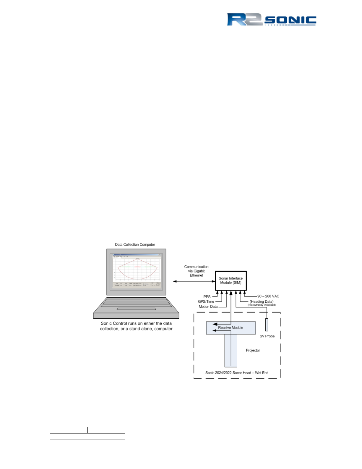
The R2Sonic Sonic 2024 and Sonic 2022 Multibeam Echosounder (MBES) is based on fifth generation
Sonar Architecture that networks all of the modules and embeds the processor and controller in the
sonar head’s Receive Module to make for a very simple installation. The Sonic Control Graphical
User Interface (GUI) is a simple program that can be installed on any Windows based computer and
allows the surveyor to control the operating parameters of the Sonic 2024/2022. Sonic Control
communicates with the Sonar Interface Module (SIM) via Ethernet. The SIM supplies power to the
sonar head, synchronises multiple heads, time tags sensor data, relays commands to the sonar head,
and routes the raw multibeam data to the customer’s Data Collection Computer (DCC).
The Sonic 2024 and Sonic 2022 work on a user selectable frequency range of 200 kHz to 400 kHz so
it is adaptable to a wide range of survey depths and conditions. The user can adjust the operating
frequency, via the Sonic Control GUI, on the fly, without having to shut down the sonar system or
change hardware or halt recording data. The Sonic 2024/2022 has a user selectable opening angle,
from 10° to 160°, using all 256 beams; the desired opening angle can be selected on the fly without
a halt to data recording. The selected swath angle can also be rotated port or starboard, whilst
recording, to direct the highly concentrated beams towards the desired target. Both the opening
angle and swath rotation can be controlled via the mouse cursor.
Figure 1: Sonic 2024/2022 Block Diagram
Page 19 of 210
Version 5.0 Rev r002
Date 05-08-2014
METRIC
IMPERIAL
10mm (0.010m)
0.39 inches
100mm (0.100m)
3.9 inches
1000mm (1.0 metre)
39.4 inches
100 grams (0.100kg)
3.5 ounces
1000 grams (1.0 kilogram)
2.2 pounds
10° C
50°F
1.2 How to use this Manual
This manual is designed to cover all aspects of the installation and operation of the Sonic 2024 and
Sonic 2022. It is, therefore, recommended that the user read through the entire Operation Manual
before commencing the installation or use of the equipment.
1.2.1 Standard of Measurement
The Metric system of measurement is utilised throughout this manual; this includes temperature in
degrees Celsius.
Table 1: Metric to Imperial conversion table
Page 20 of 210
Version 5.0 Rev r002
Date 05-08-2014
Part No. 96000001

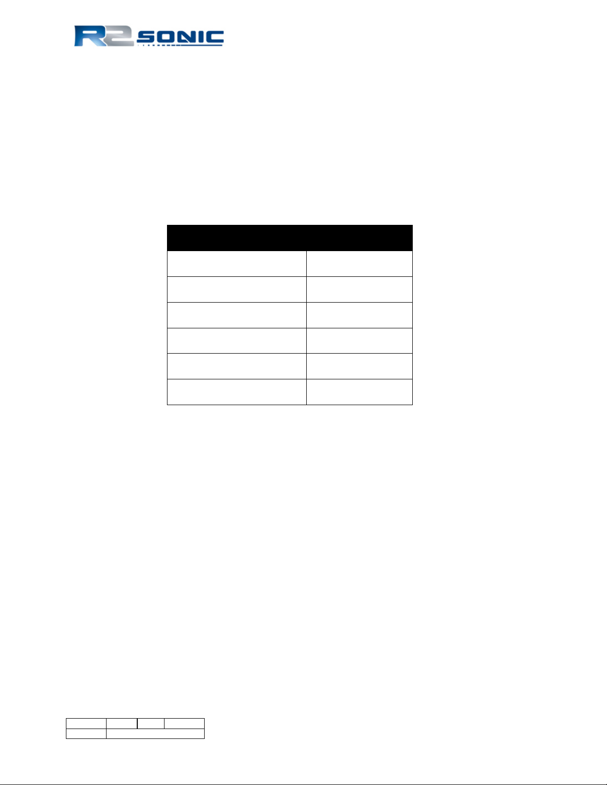
2 SONIC SPECIFICATIONS
System Feature
Specification
Frequency
400kHz / 200kHz
Beamwidth – Across Track (at nadir)
0.5°@ 400kHz / 1.0° @ 200kHz
Beamwidth – Along Track (at nadir)
1.0° @ 400kHz / 2.0° @ 200kHz
UHR Beamwidth (at nadir)
0.3° Across Track x 0.6° Along Track
Number of Beams
256
Swath Sector
10° to 160° (user selectable)
UHR Swath Sector
10° to 60° (user selectable)
Maximum Slant Range
1200 metres
Pulse Length
15µSec – 1000µSec
Pulse Type
Shaped Continuous Wave (CW)
Depth Rating
100 metres (3000 metres optional)
Operating Temperature
-10° C to 40° C
Storage Temperature
-30° C to 55° C
System Feature
Specification
Frequency
400kHz / 200kHz
Beamwidth – Across Track (at nadir)
1.0°@ 400kHz / 2.0° @ 200kHz
Beamwidth – Along Track (at nadir)
1.0° @ 400kHz / 2.0° @ 200kHz
UHR Beamwidth (at nadir)
0.6° Across Track x 0.6° Along Track
Number of Beams
256
Swath Sector
10° to 160° (user selectable)
UHR Swath Sector
10° to 60° (user selectable)
Maximum Slant Range
1200 metres
Pulse Length
15µSec – 1000µSec
Pulse Type
Shaped Continuous Wave (CW)
Depth Rating
100 metres (3000 metres optional)
Operating Temperature
-10° C to 40° C
Storage Temperature
-30° C to 55° C
Component
Dimensions (L x W x D) / Dry Weight
Receiver Module
480mm x 109mm x 190mm / 12.9kg
Projector
273mm x 108mm x 86mm / 3.3kg
Sonar Interface Module (SIM)
280mm x 170mm x 60mm / 2.4kg
I2NS Sonar Interface Module (SIM)
280mm x 170mm x 126.4mm / 4.2kg
Receive module and Projector mass in water
5.9kg (Fresh)
2.1 Sonic 2024 System Specification
Table 2: System Specification
2.2 Sonic 2022 System Specification
2.3 Sonic 2024 Dimensions and Weights
Table 3: Component Dimensions and Mass
Page 21 of 210
Version 5.0 Rev r002
Date 05-08-2014

Component
Dimensions (L x W x D) / Dry Weight
Receiver Module
276mm x 109mm x 190mm / 7.7kg
Projector
273mm x 108mm x 86mm / 3.3kg
Sonar Interface Module (SIM)
280mm x 170mm x 60mm / 2.4kg
I2NS Sonar Interface Module (SIM)
280mm x 170mm x 126.4mm / 4.2kg
Receive module and Projector mass in water
4.0kg (Fresh)
Item
Specification
Mains Power
90 – 260 VAC; 45 – 65 Hz
Power Consumption (SIM and Sonar Head)
75 Watt (Sonic 2022: 54 Watt)
Power Consumption (Sonar Head Only)
50W avg.; 90W Peak (Sonic 2022: 35W avg.; 70W
Peak)
Integrated Inertial Navigation System (I2NS)
38.4W (SIM and IMU with Antennas)
Uplink/Downlink
10/100/1000Base-T Ethernet
Data Interface
10/100/1000Base-T Ethernet
Sync IN/OUT
TTL
GPS Timing
1PPS; RS232 NMEA
Auxiliary Sensors
RS232 / Ethernet
Deck Cable Length
15 metre (optional to 50 metres)
RANGE
PING RATE
2 - 7
60.0
10
55.4
15
39.4
20
30.6
25
25.0
30
21.1
35
18.3
40
16.1
50
13.0
70
9.4
100
6.7
150
4.5
200
3.4
250
2.7
300
2.3
400
1.7
450
1.5
500
1.4
700
1.0
1000
0.7
1200
0.6
WARNING
THE RECEIVE MODULE IS FILLED WITH
PRIOR TO OPERATION.
2.4 Sonic 2022 Dimensions and Weights
2.5 Sonic 2024/Sonic 2022 Electrical Interface
Table 4: Electrical Interface
2.6 Sonic 2024/2022 Ping Rates (SV = 1500.00m/sec)
OIL THAT WILL FREEZE TO A SOLID AT
-10°C. STORAGE BELOW THIS
TEMPERATURE (TO -30°C) IS POSSIBLE IF
THE HEAD IS SLOWLY THAWED OUT
Table 5: Ping Rate table
Page 22 of 210
Version 5.0 Rev r002
Date 05-08-2014
Part No. 96000001
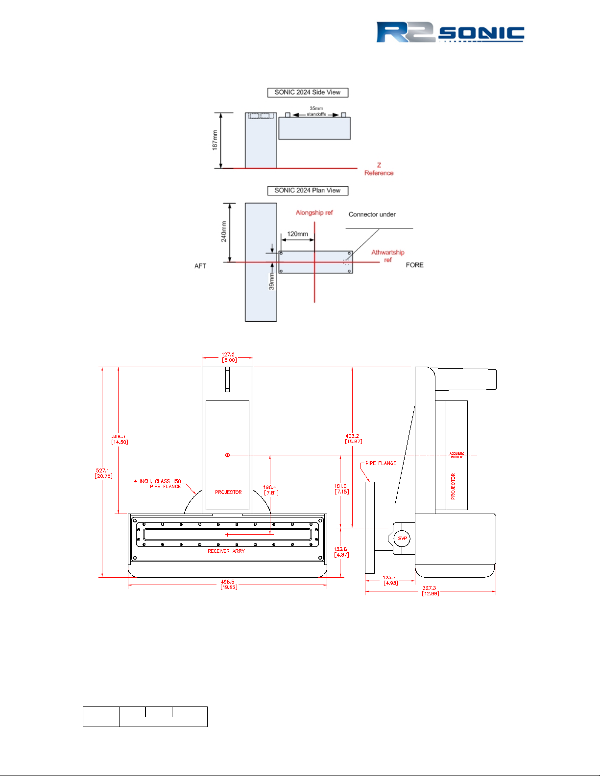
2.7 Acoustic Centre
Figure 2: Sonic 2024 Acoustic Centre
Figure 3: Sonic 2024 Acoustic Centre as Mounted
Centre of Flange to Alongship offset = 0.182m (0.597ft)
Top of Flange to Z reference = 0.327m (1.073ft)
Page 23 of 210
Version 5.0 Rev r002
Date 05-08-2014
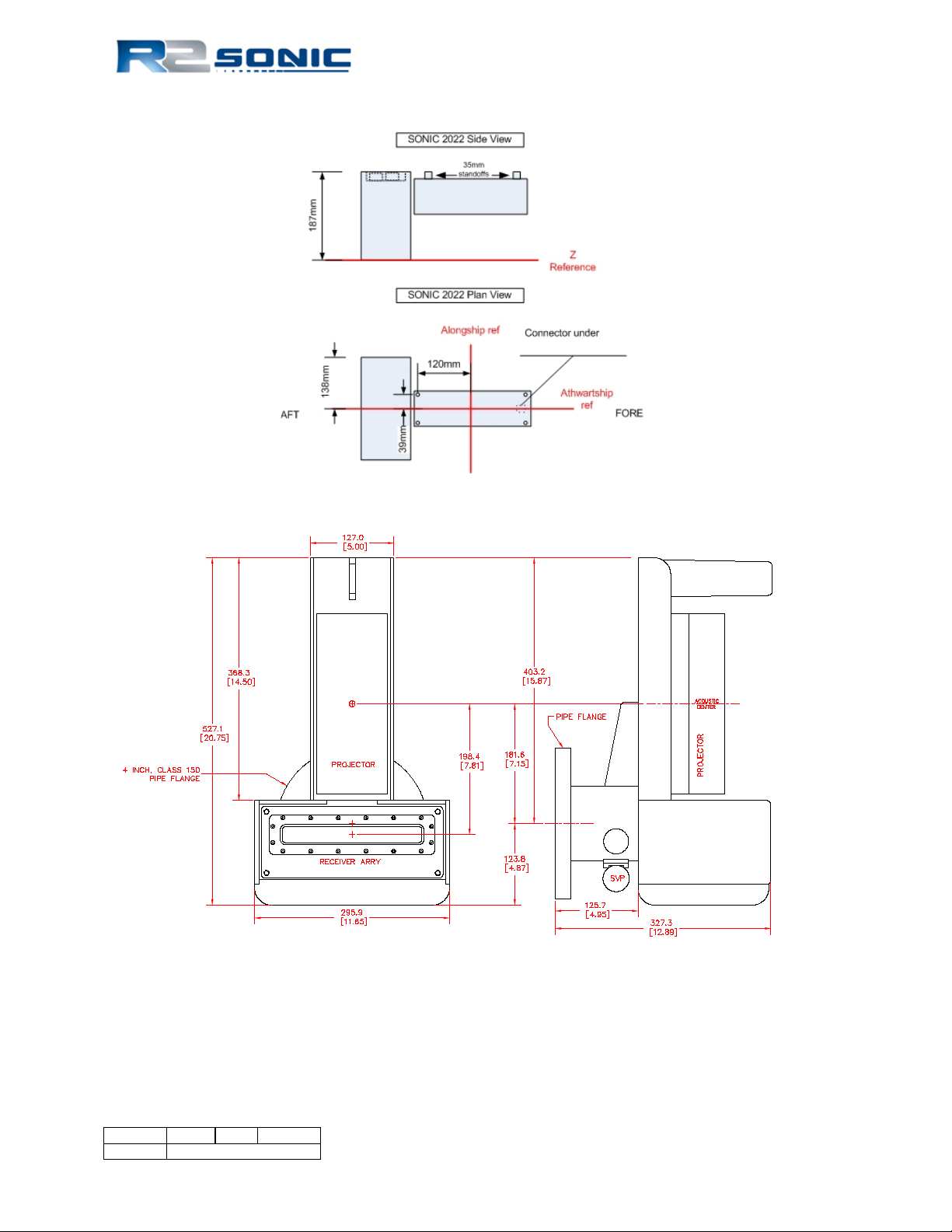
Figure 4: Sonic 2022 Acoustic Centre
Figure 5: Sonic 2022 Acoustic Centre as Mounted
Centre of Flange to Alongship offset = 0.182m (0.597ft)
Top of Flange to Z reference = 0.327m (1.073ft)
Page 24 of 210
Version 5.0 Rev r002
Date 05-08-2014
Part No. 96000001
3 SONIC 2024/2022 SONAR HEAD INSTALLATION – Surface Vessel
WARNING
DECK LEAD MINIMUM BEND RADIUS =
150MM
The Sonic 2024/2022 can be installed on an over-the-side pole, through a moon pool, or as a
permanent hull mount. The light weight, small size, and low power consumption makes the Sonic
2024/2022 ideal for underwater vehicle (ROV and AUV) installations.
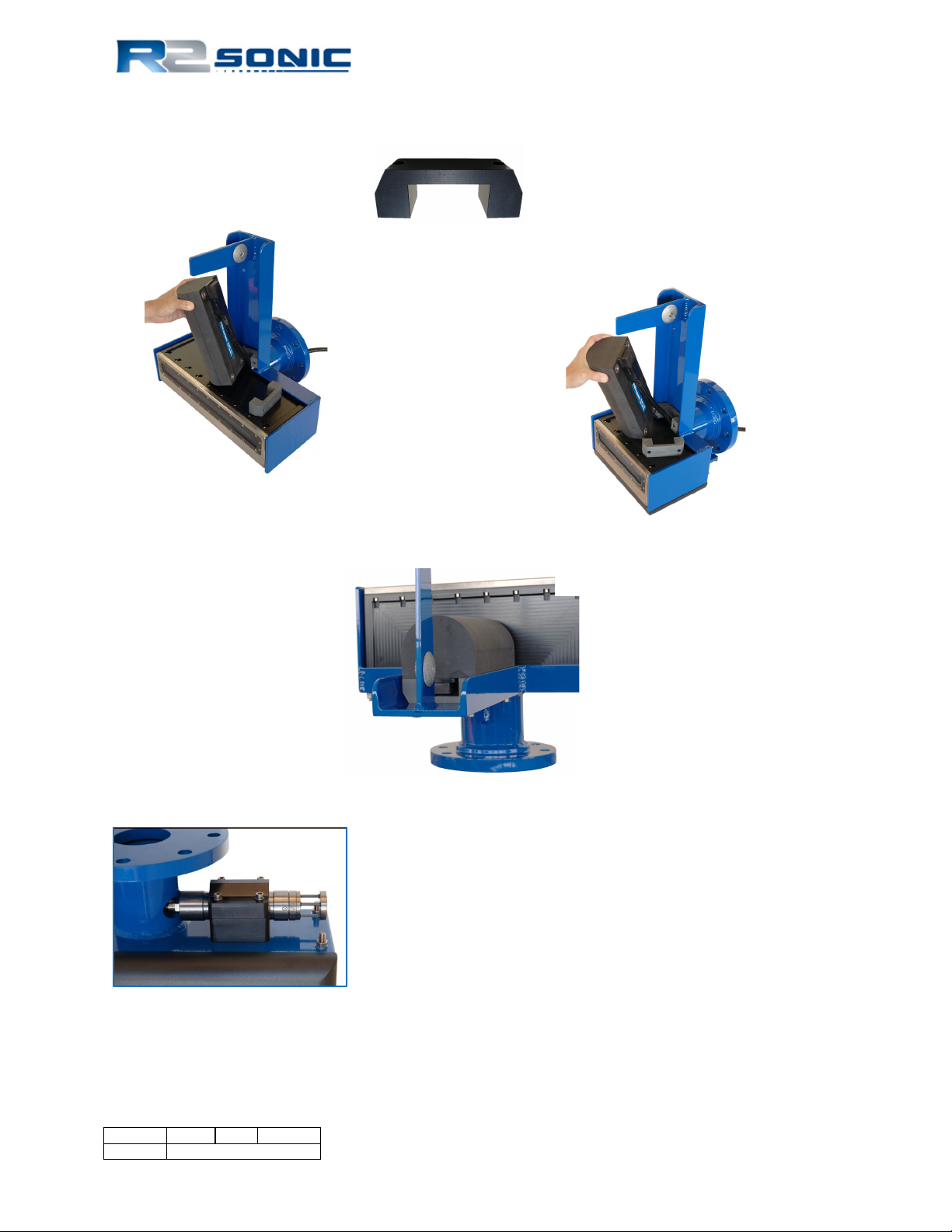
3.1 Sonic 2024/2022 Receive Module Installation
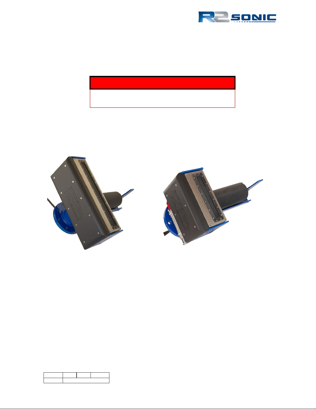
The Sonic 2024/2022 sonar head is mounted on the standard R2Sonic mounting frame as shown
below.
Figure 6: Sonic 2024 and Sonic 2022 on the mounting frame
If the Sonic 2024/2022 sonar head is not pre-mounted, the following guidelines must be followed
for proper operation of the system.
• The Receive Module is orientated with the narrow part of the face towards the projector
(see above).
• The projector is orientated with the connector towards the end with the protective fin.
• The Projector must be mounted with the correct 35mm standoffs in place.
Page 25 of 210
Version 5.0 Rev r002
Date 05-08-2014
Sonic 2022
Sonic 2024
Sonic 2022
Sonic 2024
When inserting or removing
3.1.1 Mounting the Sonic 2024/2022 Receive Module
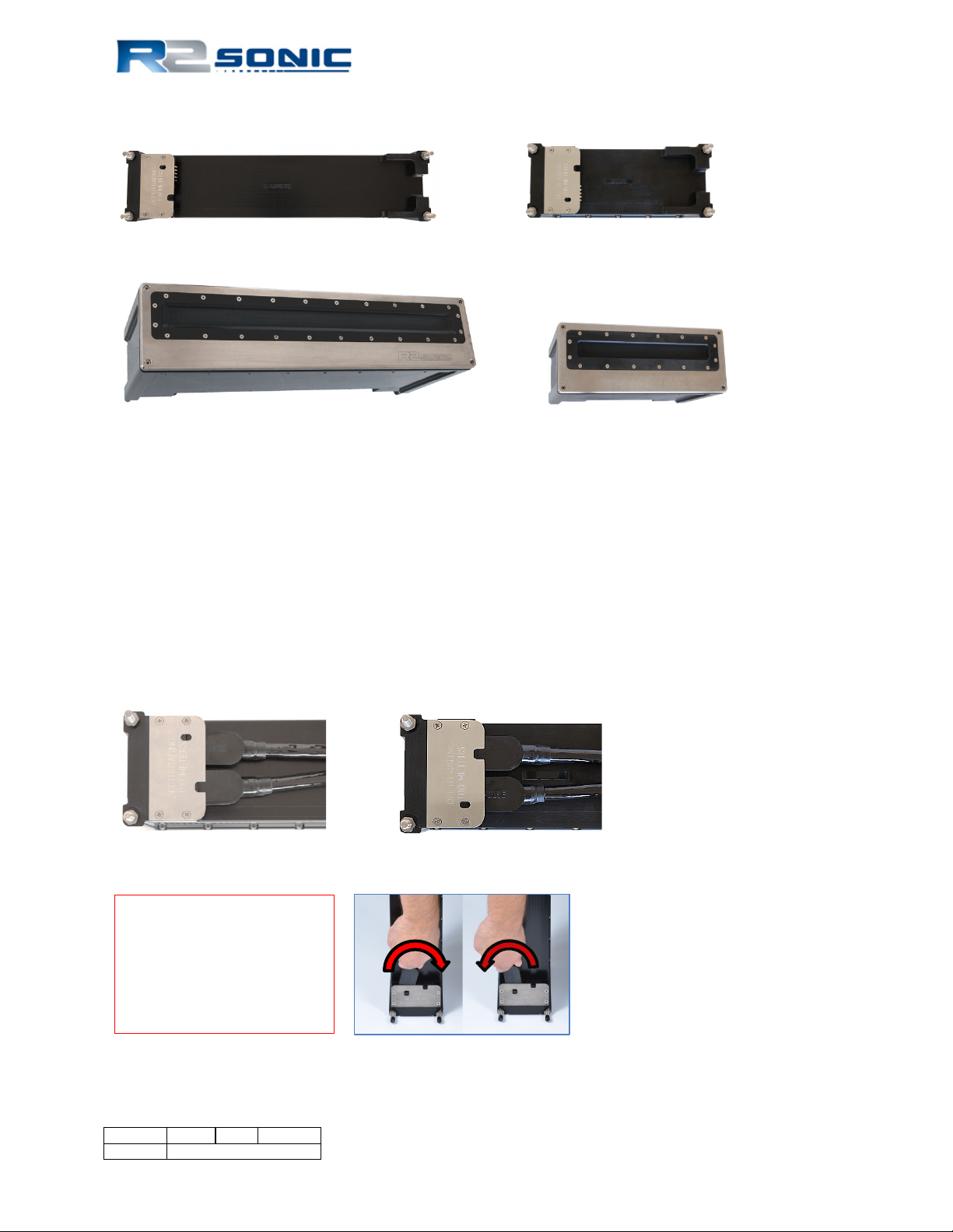
Figure 7: Top side of Receive Module
Figure 8: Receive Module Face
3.1.2 Receive Module
The Receive Module has two connectors; the female connector is for the Projector cable, the male
connector is for the deck lead that goes to the SIM. There is a securing ‘ear’ on top of the Receive
Module to secure the cables with a cable tie or other similar securing methods. Seat the 0.439m
projector cable first. A light spray of silicone lubricant (3M Silicone Lubricant, 3M ID: 62-4678-4930-
3) will aid in seating the connectors. Silicone grease is never to be used. The deck lead passes
through the hydrophone pole and then through the flange opening. Seat the deck lead after seating
the projector cable. ENSURE that all connections are tight with no visible gaps.
Figure 9: Seated connectors (Sonic 2024 on left and Sonic 2022 on right)
the connector, use a left to
right or back and forth
movement and never an up
and down movement.
Page 26 of 210
Version 5.0 Rev r002
Date 05-08-2014
Part No. 96000001
Figure 10: Connector wiggle - back and forth NOT up and down
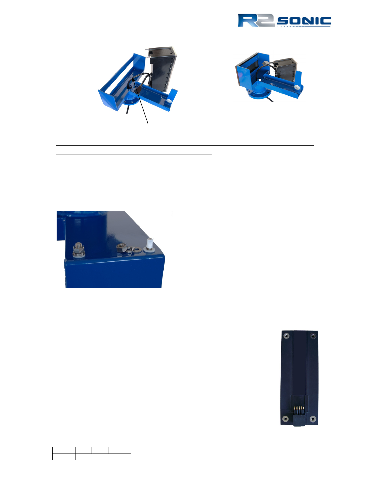
Figure 12: Sonic 2024 Projector
Sonic 2024
Sonic 2022
SV Probe block is secured, via screws, though the underside of the mounting frame
Figure 11: Receive Module with cables connected
Prior to mounting the Receive Module, the block that holds the sound velocity probe must be
secured through the underside of the mounting bracket. Next, mount the Receive Module in the
mounting frame. This can be most easily done by putting the receive module face on a piece of
cardboard or other material and then lowing the mounting frame down with the threaded bolts
passing through the mounting frame. The threads, of the securing bolts, after passing through the
frame, must be wrapped with 2 wraps of Teflon™ tape. This is to prevent galling where the nut will
freeze on the bolt. Do not tighten beyond 17Newton metre (150 pound-inch or 12.5 pound-foot).
Figure 13: Position the insulating bushing, then wrap threads with Teflon tape, then secure with flat washer, locking
washer and then nut.
3.1.3 Mounting the Projector
The projector is secured to the frame with two, 35mm stand offs. The
stand-offs allow room for the Projector to Receive Module cable to be
run. A 6mm drive hex screw secures the projector through the standoff. The Projector’s connector faces towards the protection fin.
Connect the 0.439m interconnect cable’s female end to the Projector’s
male bulk head connector. When the connectors are mated, there
should be no visible gap between them. A very light spray of silicon
lubricant will aid seating the connector.
Page 27 of 210
Version 5.0 Rev r002
Date 05-08-2014
Sonic 2024
Sonic 2022
Figure 14: Projector Stand-off
Figure 15: Mounting the projector
Figure 16: View of the mounted Projector; NB. Connector is facing protective fin
Figure 17: SV Probe mounted in block
Page 28 of 210
Version 5.0 Rev r002
Date 05-08-2014
Part No. 96000001
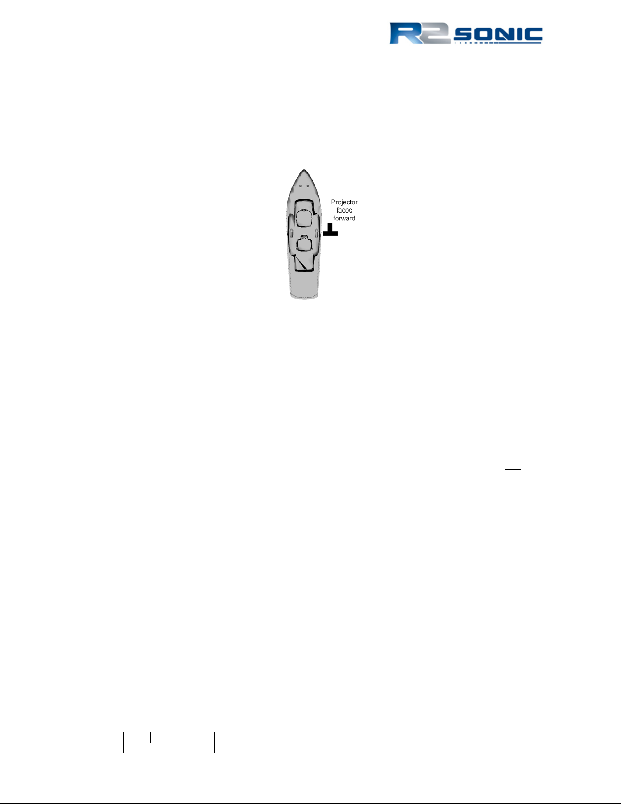
3.1.4 Correct Orientation of the Sonic 2024 and Sonic 2022
The Sonic 2024/2022 is designed to be installed with the projector facing forward, or towards the
bow. However, if the installation requires the projector to face aft, in Sonic Control, the user can
select the orientation to projector aft and this will re-orientate the data output to reflect the
projector orientation.
Figure 18: Correct Orientation of the Sonic 2024 and the Sonic 2022
3.1.5 Deck Test Prior to Deployment
It is highly recommended that the operation of the sonar be verified prior to putting the sonar or
vessel into the water. The deck test will test both the receiver and the transmitter.
3.1.5.1 Communications test
The first test is to ensure that computer, running Sonic Control, can communicate with both the
sonar head and the SIM.
• Make sure that Sonic Control is installed in the root directory on the computer and not
under ProgramFiles nor on the desktop
• Make sure all firewalls are off
• Make sure all virus checkers are disabled
• Verify the IP4 configuration for the network card being used for the sonar
• Make sure that the files, in the Sonic Control directory, are not Read-only, or otherwise
protected by the operating system
3.1.5.2 Receiver rub test
This tests the receiver and the receive elements
• Turn transmit power off by positioning the cursor over the Power button, then Shift + left
mouse button; this will set transmit power to 0
• Reduce the range
• Turn Acoustic Imagery on (under Settings | Displays)
• Increase Gain to 30
Page 29 of 210
Version 5.0 Rev r002
Date 05-08-2014

• Have someone rub the receiver face, slowly, with their hand, along the face of the receiver.
Noise will be seen, in the display, that will correspond to the rubbing
• If noise is not seen, try adjusting range or gain
• If noise is not seen, check the Impulse connector, on the receiver
3.1.5.3 Transmitter test
This tests that the transmitter is transmitting
• Have someone position their ear close to the projector
• Set ping rate (Settings | Sonar settings) to 2 Hz
• Set pulse width to 100µsecs
• Slowly bring up Power
• A distinct ‘click’ should be heard at the 2 Hz ping rate
• If no clicking is heard, increase pulse width and power
• If no clicking is heard, check the projector cable connection
• If no clicking is heard, open the Status window and check TX voltage (V); voltage should
increase / decrease with increase / decrease in Power
3.1.5.4 Problems with Deck Test
If there are any issues, with the Deck Test, please contact R2Sonic Support immediately. R2Sonic
Support can be contacted via email: R2Support@R2Sonic.com
; telephone/SMS: +1.805.259.8142;
Skype: chaswbrennan
Page 30 of 210
Version 5.0 Rev r002
Date 05-08-2014
Part No. 96000001
 Loading...