

Page 1
Page 2
Page 3

OPERATING MANUAL
PORTABLE APPLIANCE TESTER
PAT-806
SONEL SA
ul. Wokulskiego 11
58-100 Świdnica, Poland
Version 1.08 13.01.2017
Page 4

OPERATING MANUAL PAT-806 version 1.08
2
PAT-806 meter is a modern, high-quality meter, easy and safe in operation. Please acquaint yourself
with the present manual in order to avoid measuring errors and prevent possible problems related to
operation of the meter.
Page 5

OPERATING MANUAL PAT-806 version 1.08
3
CONTENTS
1 SAFETY .................................................................................................................... 5
2 GENERAL DESCRIPTION AND FEATURES OF THE INSTRUMENT ......... 6
3 SWITCHING ON AND GENERAL SETTINGS .................................................. 8
3.1 POWER SUPPLY ...................................................................................................... 8
3.2 START TEST AFTER SWITCHING THE METER ON ......................................................... 8
3.3 GENERAL SETTINGS - MENU ................................................................................. 9
3.3.1 Setting date and time ................................................................................... 10
3.3.2 Communication with PC .............................................................................. 11
3.3.3 Firmware update ......................................................................................... 11
3.3.4 Setting the bar-code reader ......................................................................... 12
3.3.5 Printer Settings ............................................................................................ 13
3.3.6 Transferring data to a pen-drive ................................................................. 14
3.3.7 Setting nominal network voltage ................................................................. 15
3.3.8 Setting current values in the measurement of RPE on IEC lead test ............. 16
3.3.9 Configuration of settings from PC ............................................................... 16
4 MEASUREMENTS ................................................................................................ 19
4.1 PRELIMINARY TEST ............................................................................................... 20
4.2 MEASUREMENT OF PROTECTIVE LEAD RESISTANCE USING 200 MA CURRENT .......... 21
4.3 COMPENSATION OF THE TEST LEAD RESISTANCE DURING THE MEASUREMENT OF THE
PROTECTIVE LEAD RESISTANCE USING 200 MA CURRENT (AUTO-ZERO) ................. 24
4.4 MEASUREMENT OF PROTECTIVE LEAD RESISTANCE USING 10/25 A CURRENT ......... 24
4.4.1 Two-wire measurement of protective lead resistance using 10/25 A
current ......................................................................................................... 25
4.4.2 Compensation of the test lead resistance during the measurement of the
protective lead resistance using 10 A or 25 A current (auto-zero).............. 26
4.4.3 Three-wire measurement of protective lead resistance using 10/25 A
current ......................................................................................................... 27
4.4.4 Four-wire measurement of protective lead resistance using 10/25 A
current ......................................................................................................... 27
4.5 MEASUREMENT OF INSULATION RESISTANCE ......................................................... 28
4.5.1 R
ISO
measurement on devices of Class I ....................................................... 28
4.5.2 R
ISO
measurement on devices of Class II (III) .............................................. 30
4.5.3 Three-point R
ISO
measurement on welding equipment ................................. 31
4.6 MEASUREMENT OF SUBSTITUTE LEAKAGE CURRENT .............................................. 33
4.7 MEASUREMENT OF PE LEAKAGE CURRENT ........................................................... 35
4.8 MEASUREMENT OF DIFFERENTIAL LEAKAGE CURRENT .......................................... 37
4.9 MEASUREMENT OF TOUCH LEAKAGE CURRENT ..................................................... 38
4.10 MEASUREMENT OF LEAKAGE CURRENT IN THE PRIMARY CIRCUIT OF THE WELDING
MACHINE USING PAT IP ADAPTER ....................................................................... 39
Page 6

OPERATING MANUAL PAT-806 version 1.08
4
4.11 RATED VOLTAGE MEASUREMENT ON WELDING EQUIPMENT WITHOUT LOAD ........... 42
4.12 LEAKAGE CURRENT MEASUREMENT ON WELDING CIRCUIT IL ................................. 44
4.13 MEASUREMENT OF CURRENT, POWER CONSUMPTION AND VOLTAGE ...................... 45
4.14 IEC LEAD TEST .................................................................................................... 46
4.15 AUTOMATIC TESTS ............................................................................................... 47
5 MEMORY OF MEASUREMENT RESULT DATA .......................................... 51
5.1 STORING THE MEASUREMENT RESULTS IN THE MEMORY ........................................ 51
5.2 VIEWING MEMORY DATA ...................................................................................... 53
5.3 DELETING MEMORY DATA .................................................................................... 53
5.3.1 Deleting bank data ...................................................................................... 53
5.3.2 Deleting the whole memory ......................................................................... 54
6 REPORT PRINTING ............................................................................................ 54
7 DATA TRANSMISSION ...................................................................................... 55
7.1 COMPUTER CONNECTION ACCESSORIES ............................................................... 55
7.2 DATA TRANSMISSION WITH USB PORT .................................................................. 55
8 CLEANING AND MAINTENANCE ................................................................... 55
9 STORAGE .............................................................................................................. 55
10 DISMANTLING AND DISPOSAL ...................................................................... 55
11 ANNEXES .............................................................................................................. 56
11.1 TECHNICAL SPECIFICATIONS ................................................................................ 56
11.2 STANDARD EQUIPMENT ........................................................................................ 63
11.3 OPTIONAL ACCESSORIES ...................................................................................... 63
12 MANUFACTURER ............................................................................................... 64
Page 7

OPERATING MANUAL PAT-806 version 1.08
5
1 Safety
PAT-806 meter is designed for performing check tests on electrical equipment, providing measurement results which determine the safety status of tested devices. Therefore, in order to provide
conditions for correct operation and the correctness of the obtained results, the following recommendations must be observed:
Before you proceed to operate the meter, acquaint yourself thoroughly with the present manual
and observe the safety regulations and specifications determined by the producer.
Any application that differs from those specified in the present manual may result in a damage to
the device and constitute a source of danger for the user.
PAT-806 meter must be operated only by appropriately qualified personnel with relevant certifi-
cates authorising the personnel to perform works on electric systems. Operating the meter by unauthorised personnel may result in damage to the device and constitute a source of danger for
the user.
The instrument must not be used with installations or equipment situated in dangerous environ-
ments, e.g. where fire or explosion hazards exist.
It is unacceptable to operate the following:
A damaged meter which is completely or partially out of order,
A meter with damaged test leads insulation,
A meter stored for an excessive period of time in disadvantageous conditions (e.g. excessive
humidity). If the meter has been transferred from a cool to a warm environment with a high
level of relative humidity, do not start measurements until the meter is warmed up to the ambient temperature (approximately 30 minutes).
The meter may be supplied only from grounded mains sockets.
Before measurements may commence, make sure the test leads are connected to the appropri-
ate measurement sockets.
Do not touch the tested device during measurements.
Banana test sockets and the socket for testing IEC cables are protected against improper con-
nection to the voltage up to 300 V AC for 60 seconds.
Repairs may be carried out only by an authorised service point.
NOTE!
Only standard and additional accessories for a given device should be used, as listed
in the "Equipment" section. Use of different accessories can lead to errors in the test
connection and can introduce additional measurement uncertainties.
NOTE!
The plug on the housing near handle must be always tightened. It can be unscrewed
only when the device is transported by an aeroplane.
Note:
Due to continuous development of the meter’s software, the actual appearance of the
display, in case of some of the functions, may slightly differ from the display presented
in this operating manual.
Page 8

OPERATING MANUAL PAT-806 version 1.08
6
2 General description and features of the instrument
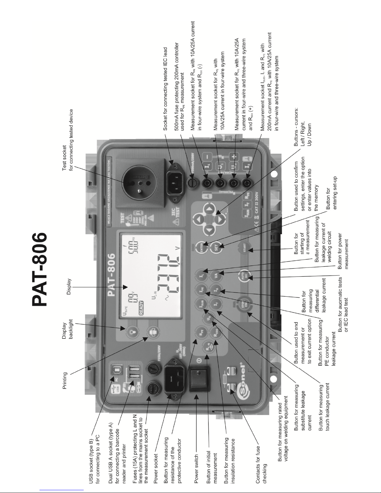
PAT-806 digital meter is intended to measure the basic parameters of portable electrical devices
(power tools, household appliances, etc.) important for their safety: protective conductor resistance,
insulation resistance, continuity of connections, the leakage current.
The meter may be used to test the equipment, in accordance with the following standards:
EN 60745-1 Hand-held motor-operated electric tools. Safety. Part 1: General requirements.
EN 61029 Safety of transportable motor operated electric tools. General requirements.
EN 60335-1 Household and similar electrical appliances. Safety. Part 1: General requirements.
EN 60950 Information technology equipment – Safety- Part 1: General requirements.
EN 60974-4 Arc welding equipment - Part 4: Periodic inspection and testing
VDE 0404-1 Prüf- und Messeinrichtungen zum Prüfen der elektrischen Sicherheit von elektri-
schen Geräten. Teil 1: Allgemeine Anforderungen.
VDE 0404-2 Prüf- und Messeinrichtungen zum Prüfen der elektrischen Sicherheit von elektri-
schen Geräten. Teil 2: Prüfeinrichtungen für Prüfungen nach Instandsetzung, Änderung oder für
Wiederholungsprüfungen.
VDE 0701-0702 Prüfung nach Instandsetzung, Änderung elektrischer Geräte. Wiederho-
lungsprüfung elektrischer Geräte. Allgemeine Anforderungen für die elektrische Sicherheit.
Basic functions of the instrument:
Measurement of network voltage and frequency
Rated voltage measurement on welding equipment
Checking the resistance of L-N circuit
Checking the fuse
Measurement of protective conductor resistance (Protection class - I):
technical measurement method
measurement with sinusoidal current of network frequency and values: 200 mA, 10 A and
25 A
adjustable measurement time
adjustable upper limit in the range of: 10 mΩ …1.99 Ω with resolution 0.01 Ω
Measurement of insulation resistance:
three test voltages: 100 V, 250 V and 500 V
measurement of insulation resistance up to 600 M
automatic discharge of the capacitance of tested object after the insulation resistance meas-
urement is completed
adjustable measurement time
adjustable lower limit within the range of 0.1 MΩ ….9.9 MΩ with resolution of 0.1 MΩ
three point measurement of insulation resistance on welding equipment
Measurement of substitute leakage current:
adjustable measurement time
adjustable upper limit in the range of: 0.01 mA ... 9.9 mA with resolution of 0.01 mA/0.1 mA
Measurement of PE leakage current
adjustable measurement time
adjustable upper limit in the range of: 0.01 mA ... 9.9 mA with resolution of 0.01 mA/0.1 mA
Page 9

OPERATING MANUAL PAT-806 version 1.08
7
Measurement of differential leakage current:
adjustable measurement time
adjustable upper limit in the range of: 0.01 mA ... 9.9 mA with resolution of 0.01 mA/0.1 mA
Measurement of touch leakage current:
adjustable measurement time
adjustable upper limit in the range of: 0.01 mA ... 1.99 mA with resolution of 0.01 mA
Leakage current measurement on welding circuit:
adjustable measurement time
adjustable upper limit in the range of: 0,1 mA…14,9 mA with resolution 0,1 mA
Power measurement:
adjustable measurement time
Current consumption measurement
IEC lead test
Other:
automatic selection of measuring range
990 memory cells for storing individual measurement results with the option to transfer them
to a PC via USB socket or printing
cooperation with the bar-code reader and printer
large, readable display with backlight option
ergonomic operation
Note:
The displayed E02 symbol informs that the 10/25 A test set is damaged. The machine
must be sent for repair.
Page 10
OPERATING MANUAL PAT-806 version 1.08
8
3 Switching on and general settings
3.1 Power supply
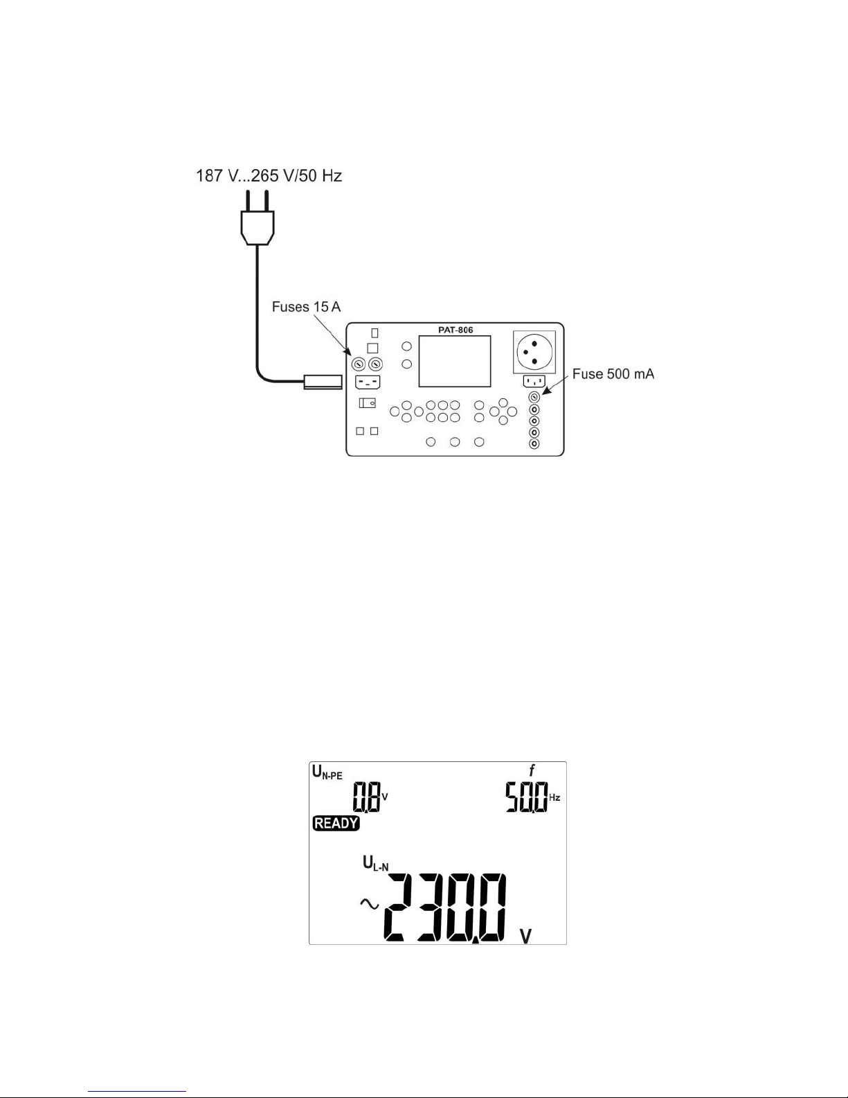
The device is powered from the network 187 V ... 265 V, 50 Hz.
Two 15 A fuses protect L and N lines from the supply socket to the test socket, they are tripped
when current consumption from the test socket is too high (>16 A).
500 mA fuse protects 200 mA current controller for RPE measurement.
3.2 Start test after switching the meter on
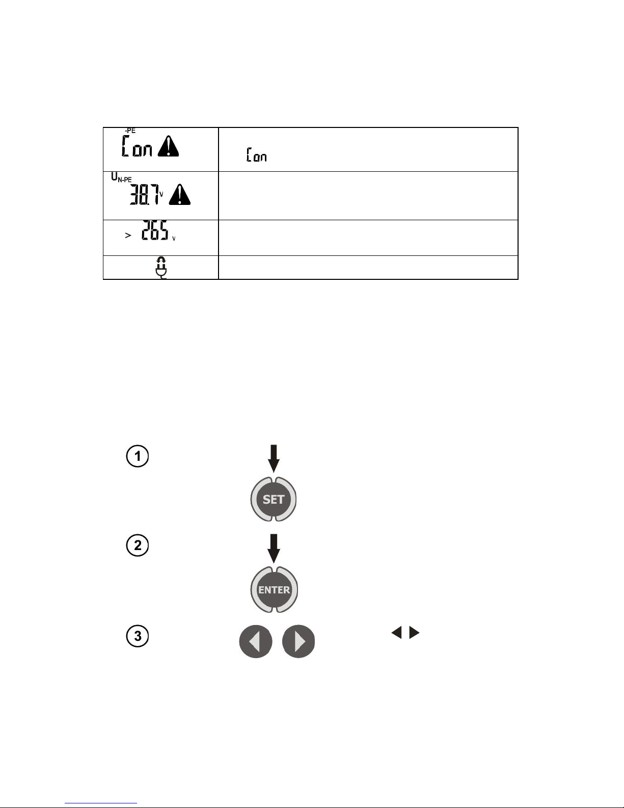
After switching on, the meter performs self-test to check its correct operational condition and
when this test is successfully completed, the meter automatically performs the following measurements:
measurement of the voltage in the power supply socket, i.e. the voltage between L and N of
power supply to the meter
measurement of mains frequency
checking the continuity PE in the power supply socket
measuring the voltage between N and PE in the power supply socket
When everything is correct the following screen is displayed:
Page 11
OPERATING MANUAL PAT-806 version 1.08
9
Notes:
- When the network voltage is below 187 V the meter turns off automatically.
Additional information displayed by the meter
, and
an acoustic signal
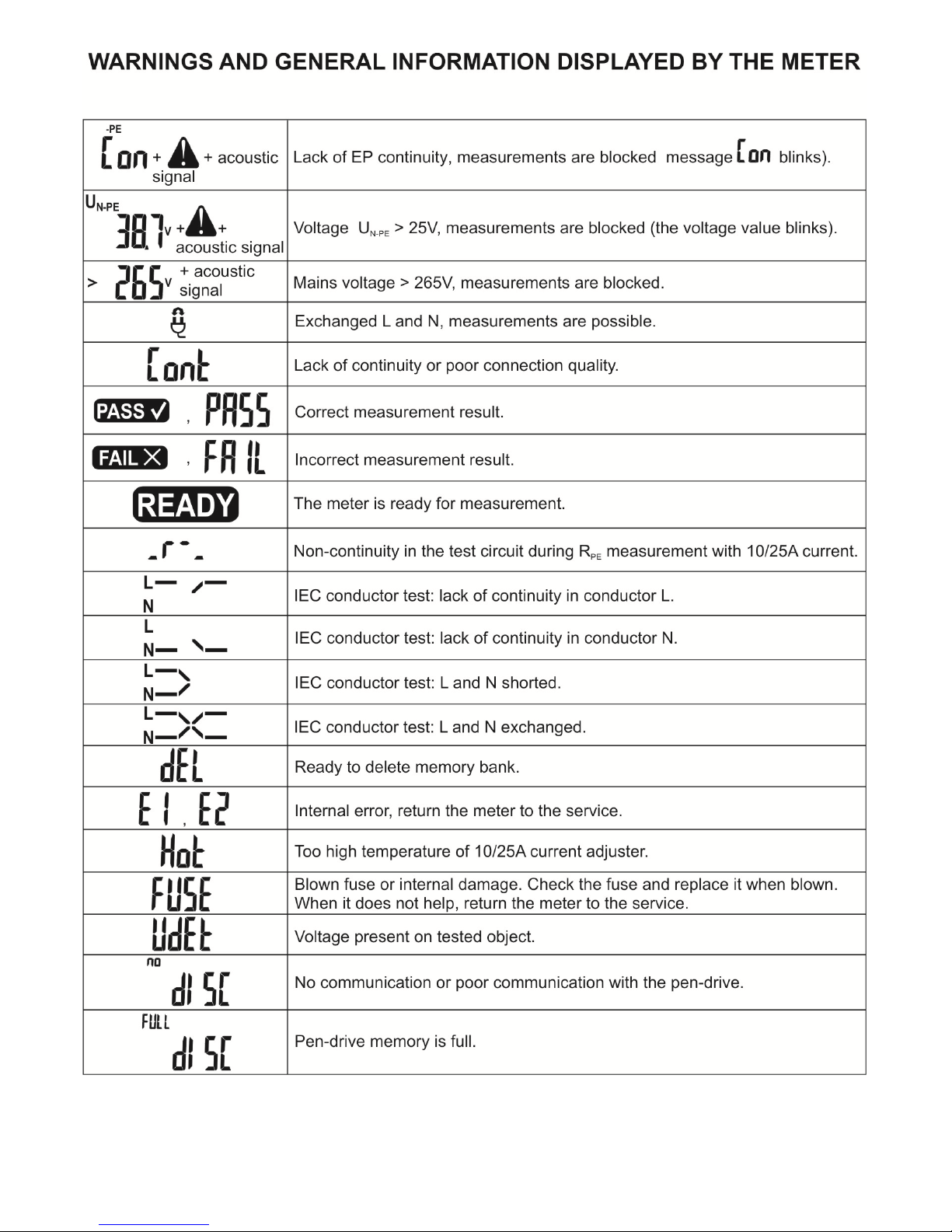
Lack of PE continuity, the measurements are blocked (message blinks).
, and
an acoustic signal
Voltage U
N-PE
> 25 V, the measurements are blocked (the
voltage value blinks).
and
an acoustic signal
Mains voltage > 265 V, measurements are blocked.
Exchanged L and N, measurements are possible.
3.3 General Settings - MENU
By pressing SET button the user enters the mode where the following actions are available:
setting date and time
communicating with PC
updating firmware
operating the meter with a bar-code reader and printer
transferring data to a pen-drive
setting nominal network voltage
setting current values in the measurement of RPE on IEC lead.
To enter the setting mode (MENU):
press SET button
Press ENTER to enter the parameter
setting.
Use buttons , to go to the
next parameter.
Page 12
OPERATING MANUAL PAT-806 version 1.08
10
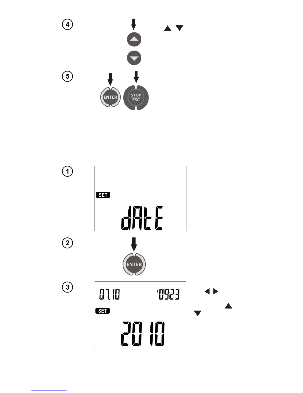
Use , to set the parameter
value.
Press ENTER to approve the setting, press ESC go to the main
MENU without changing any settings.
Notes:
- The value or symbol to be changed is blinking.
- Exit MENU using STOP/ESC.
- Settings are stored in memory after switching off the meter.
3.3.1 Setting date and time
Press ENTER.
Use , to move
to the next group of
digits, using ,
set desired val-
ue.
Page 13
OPERATING MANUAL PAT-806 version 1.08
11
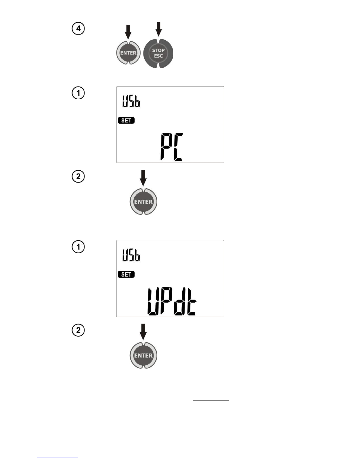
Press ENTER to confirm the settings or ESC, to exit to main MENU
without changing any settings.
3.3.2 Communication with PC
Press ENTER to start the transmission.
3.3.3 Firmware update
Press ENTER to start the transmission. On PC run the program downloaded from www.sonel.pl.
Notes:
- New versions of software for the meter are available at www.sonel.pl.
- This function may be used only by the computer proficient users.
- During programming, do not turn off the power supply of the meter and the power supply should be
stable. Do not disconnect the USB cable.
Page 14
OPERATING MANUAL PAT-806 version 1.08
12
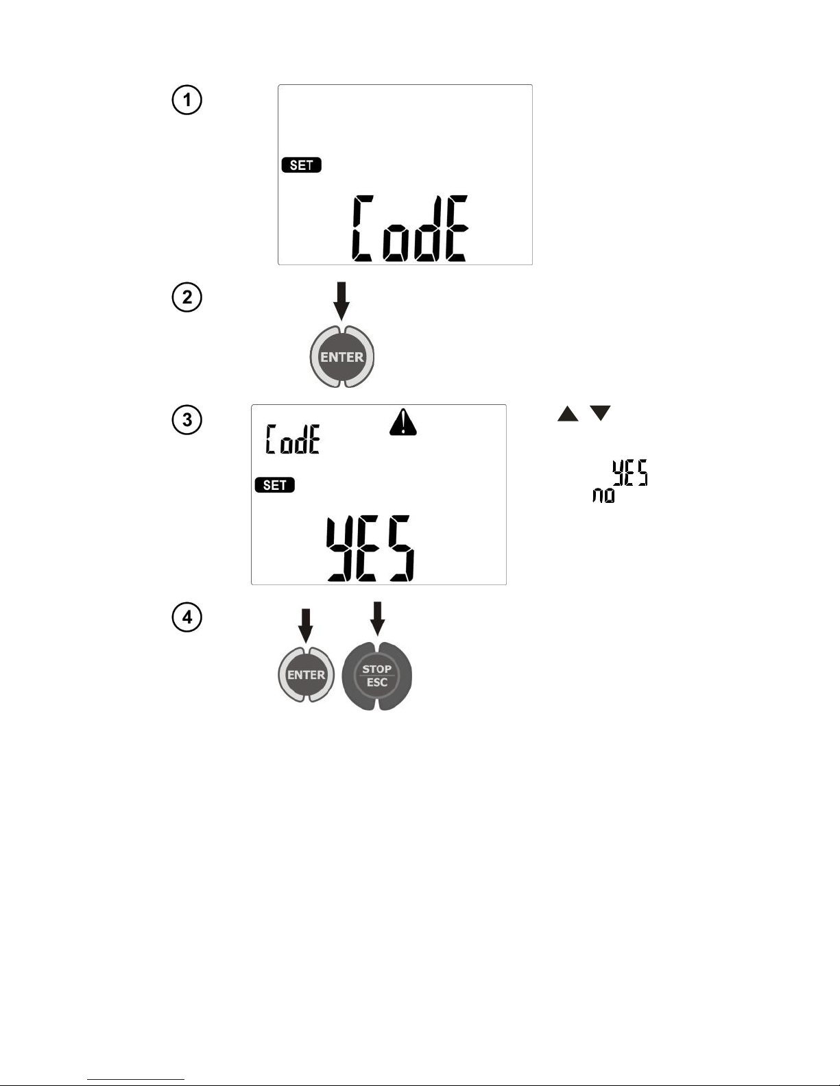
3.3.4 Setting the bar-code reader
Press ENTER.
Use , to set
the operation of the
meter with the bar-
code reader ( ) or
without it ( ).
Press ENTER, to confirm the settings, or ESC, to exit to main MENU
without changing any settings.
Notes:
- The reader and printer have been programmed to read the codes in CODE128 standard (in PAT devices we use digits only). PAT accepts only 7-character codes (e.g. "1234567"), any other are considered invalid. Therefore, if you attempt to read a 6-character code (or shorter) the reader will read it,
but PAT will not save it - the same applies to 8-character codes and longer.
- The bar-code contains only ID number of the device, no additional information is coded.
- Reader configuration:
1. Connect the reader to your PC.
2. Wait until the reader is installed on your system.
3. Point the reader at the following code pressing the button. The reader signals successful read-out
by lighting green LED and a beep.
Page 15
OPERATING MANUAL PAT-806 version 1.08
13
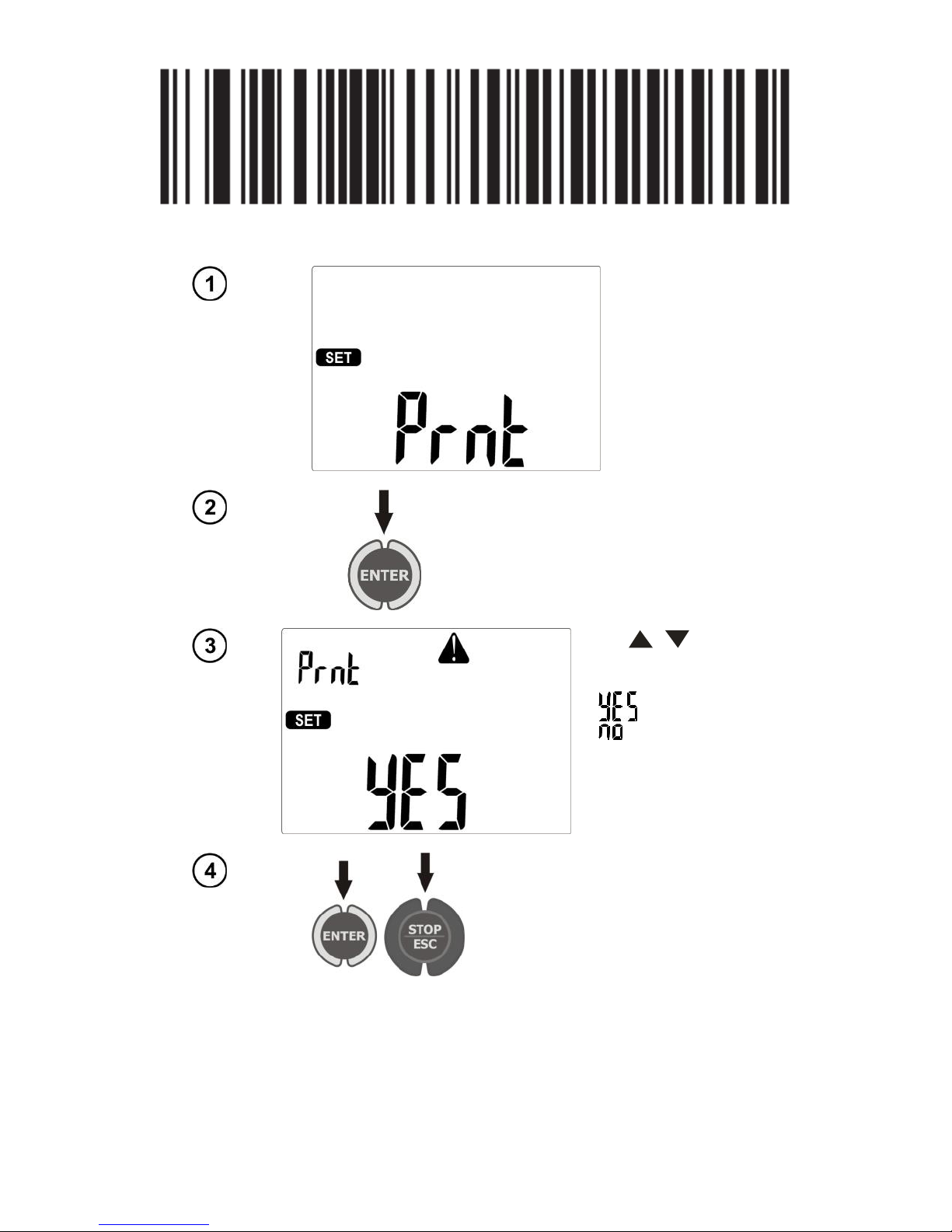
3.3.5 Printer Settings
Press ENTER.
Use , to set
the operation of the
meter with the printer
( ) or without it
( ).
Press ENTER, to confirm the settings, or ESC, to exit to main MENU
without changing any settings.
Note:
- The printer must be connected to any of the USB socket of "Host" type.
- Supported types of printers: Brother QL-720NW, Brother PT-9700PC.
Page 16
OPERATING MANUAL PAT-806 version 1.08
14
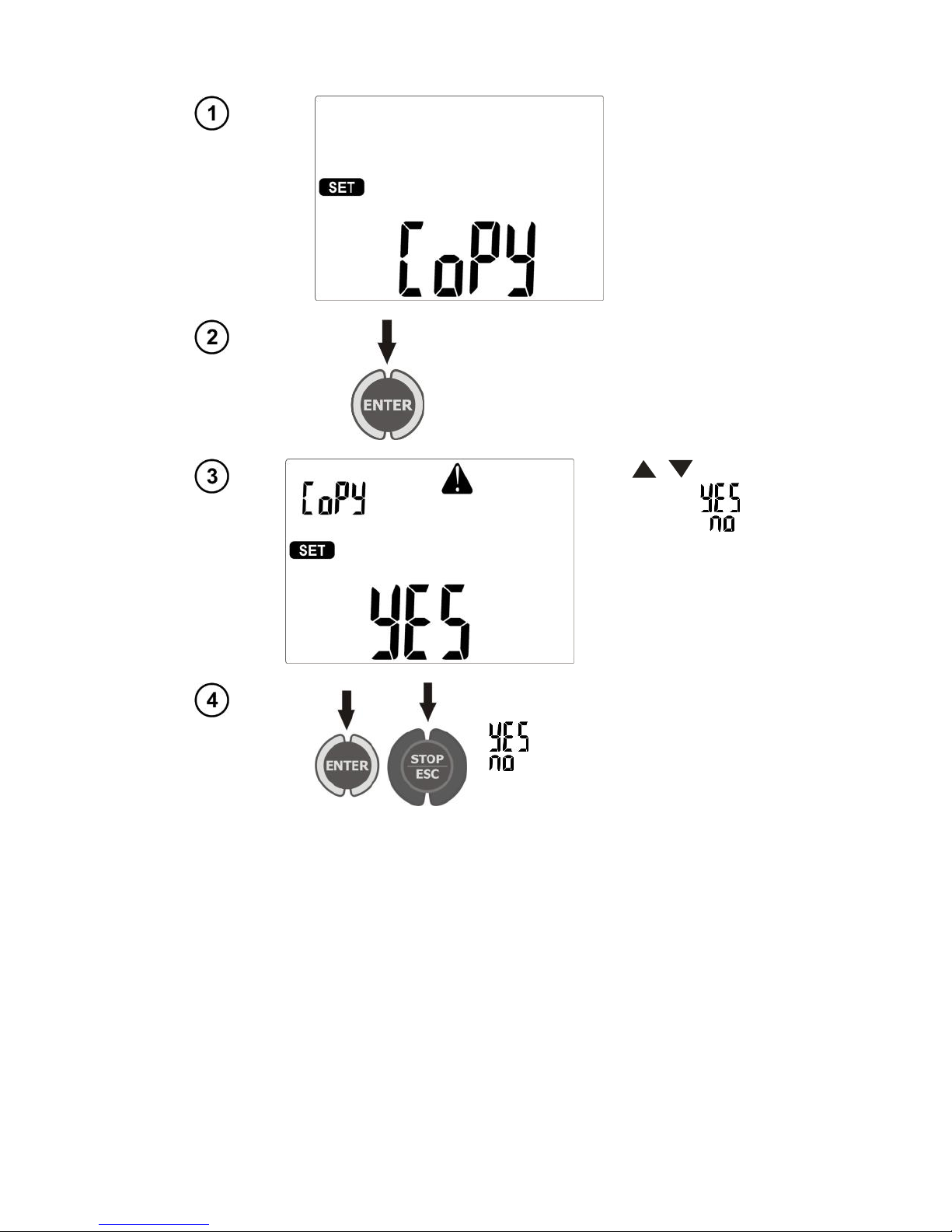
3.3.6 Transferring data to a pen-drive
Press ENTER.
Use , to set
copying data ( )
or its absence ( ).
Press ENTER, to confirm the set-
tings and start data copying for
, or to exit to main MENU for
, or ESC, to exit to main MENU
without changing any settings.
Notes:
- Pen-drive must have FAT32 file system.
- Pen-drive must be plugged into the left USB socket of "Host" type.
- The content of memory is transferred to the pen-drive as a file in an independent format interpreted
by "Sonel Reader" freeware and "Sonel PAT" commercial software.
Page 17
OPERATING MANUAL PAT-806 version 1.08
15
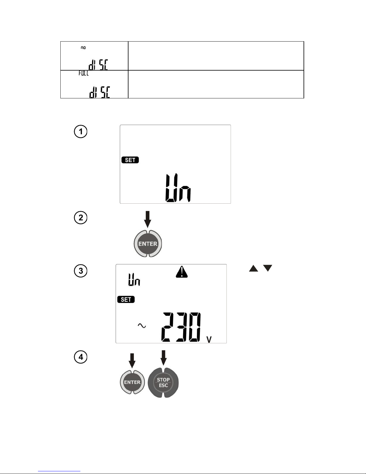
Additional information displayed by the meter
No communication or poor communication with the pendrive.
Pen-drive memory is full.
3.3.7 Setting nominal network voltage
Press ENTER.
Use , to set
the desired voltage.
Press ENTER, to confirm the settings, or ESC, to exit to main MENU
without changing any settings.
Page 18
OPERATING MANUAL PAT-806 version 1.08
16
Notes:
- Nominal network voltage is used in I
SUB
function for calculating the leakage current, which is meas-
ured at a voltage of 40V and its value is rescaled to the nominal voltage.
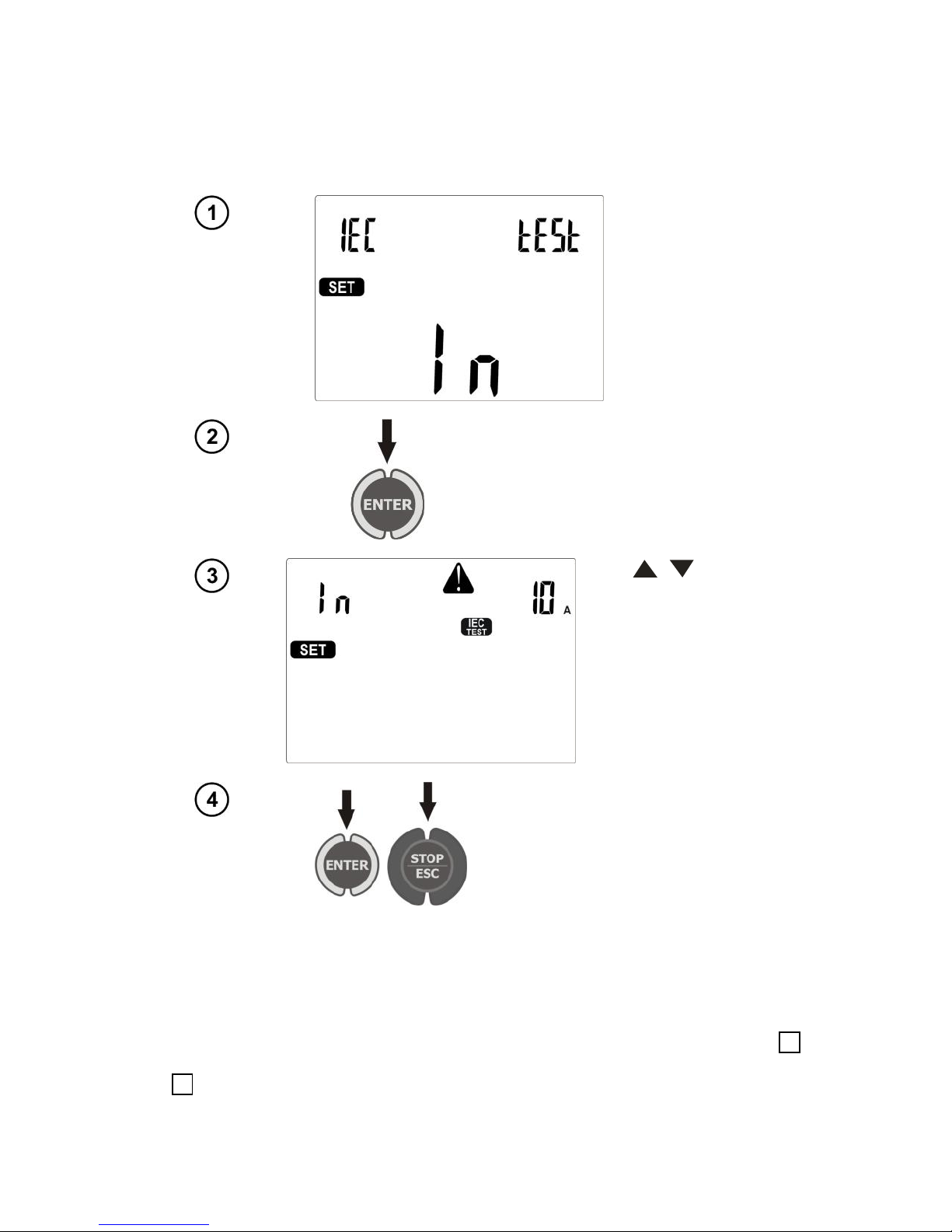
3.3.8 Setting current values in the measurement of RPE on IEC lead test
Press ENTER.
Use , to set
the test current (10 A
or 200 mA).
Press ENTER, to confirm the settings, or ESC, to exit to main MENU
without changing any settings.
3.3.9 Configuration of settings from PC
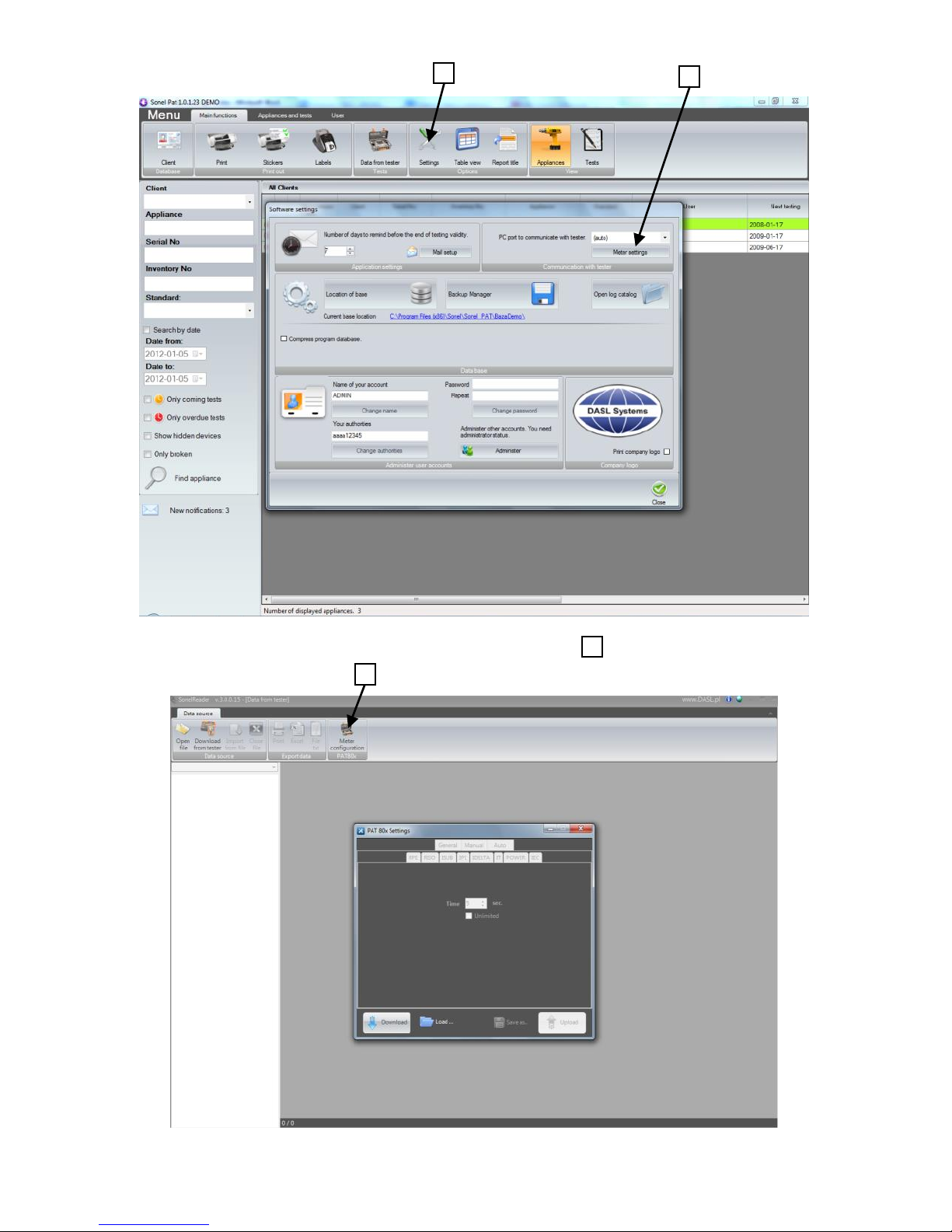
"Sonel PAT" software and "Sonel Reader" freeware delivered with the meter, enable user to configure meter settings, both in terms of general data and individual parameters of each measurement
function.
When using "Sonel PAT" software - start to configure the settings by pressing Settings 1 button
displayed in the main window (Main functions tab), then in "Software settings" window press Meter
settings 2 .
Page 19
OPERATING MANUAL PAT-806 version 1.08
17
When using "Sonel Reader" press Meter configuration PAT80x 1 button:
1
2
1
Page 20

OPERATING MANUAL PAT-806 version 1.08
18
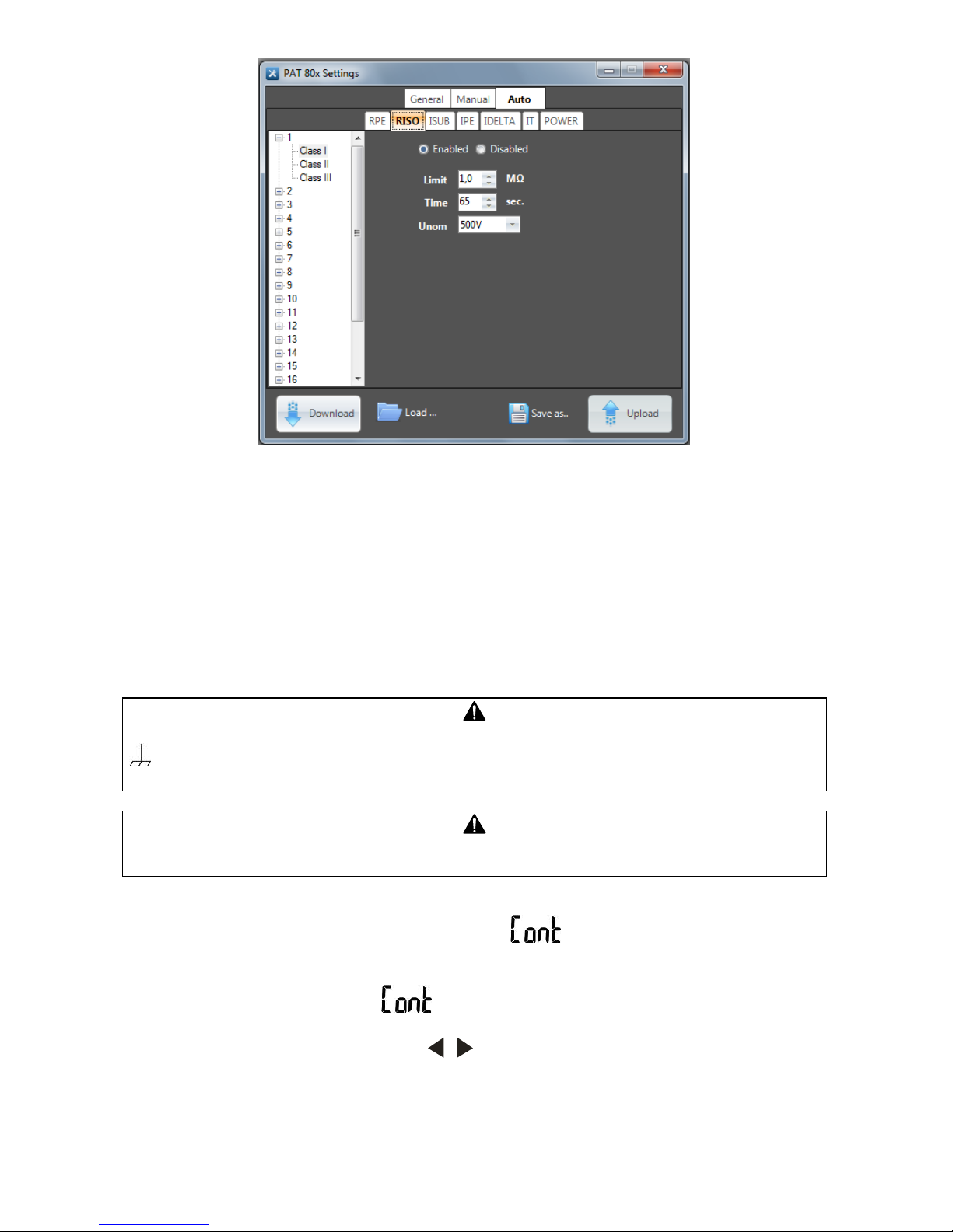
In both programs, window "PAT80x Settings" will be displayed:
Window for configuring general settings.
You can use this module to enter your contact details which will be visible on the reports printed
directly from the meter (using an optional printer). Moreover, here you can set the date, time and language of reports printed by the meter.
In Manual and Auto tabs you can configure the parameters of all measurements performed both
individually and included in auto-tests.
Window for configuring manual measurements.
Page 21
OPERATING MANUAL PAT-806 version 1.08
19
Window for configuring Auto-measurements.
The software enables user to read the current configuration of the meter, save the meter settings
into a file, upload the configuration from a file, create files with different configurations, which is a
simple way to prepare a number of configurations for various requirements, e.g. for different customers and quickly reset the meter according to current needs.
4 Measurements
Notes:
For the convenience of measurements on devices of Class II the socket marked with
symbol is connected with PE pin of the test socket. Do not connect dangerous vol-
tage to this socket.
"I2" banana socket is permanently connected to PE of IEC socket. Do not connect dangerous voltage to this socket.
- Tested device must be turned on.
- Measurement activated with defined duration time = - continuous measurement – lasts as
long as START button is pressed. Maintaining the measurement is possible by pressing ENTER with
START button kept pressed.
- Each measurement with duration = - continuous measurement – maintaining the measurement by pressing ENTER may be stopped by pressing STOP/ESC.
- After completing each measurement use , to see parameters (limits) including the date and
time of measurement.
- All data can be entered using the program on your PC.
Page 22
OPERATING MANUAL PAT-806 version 1.08
20
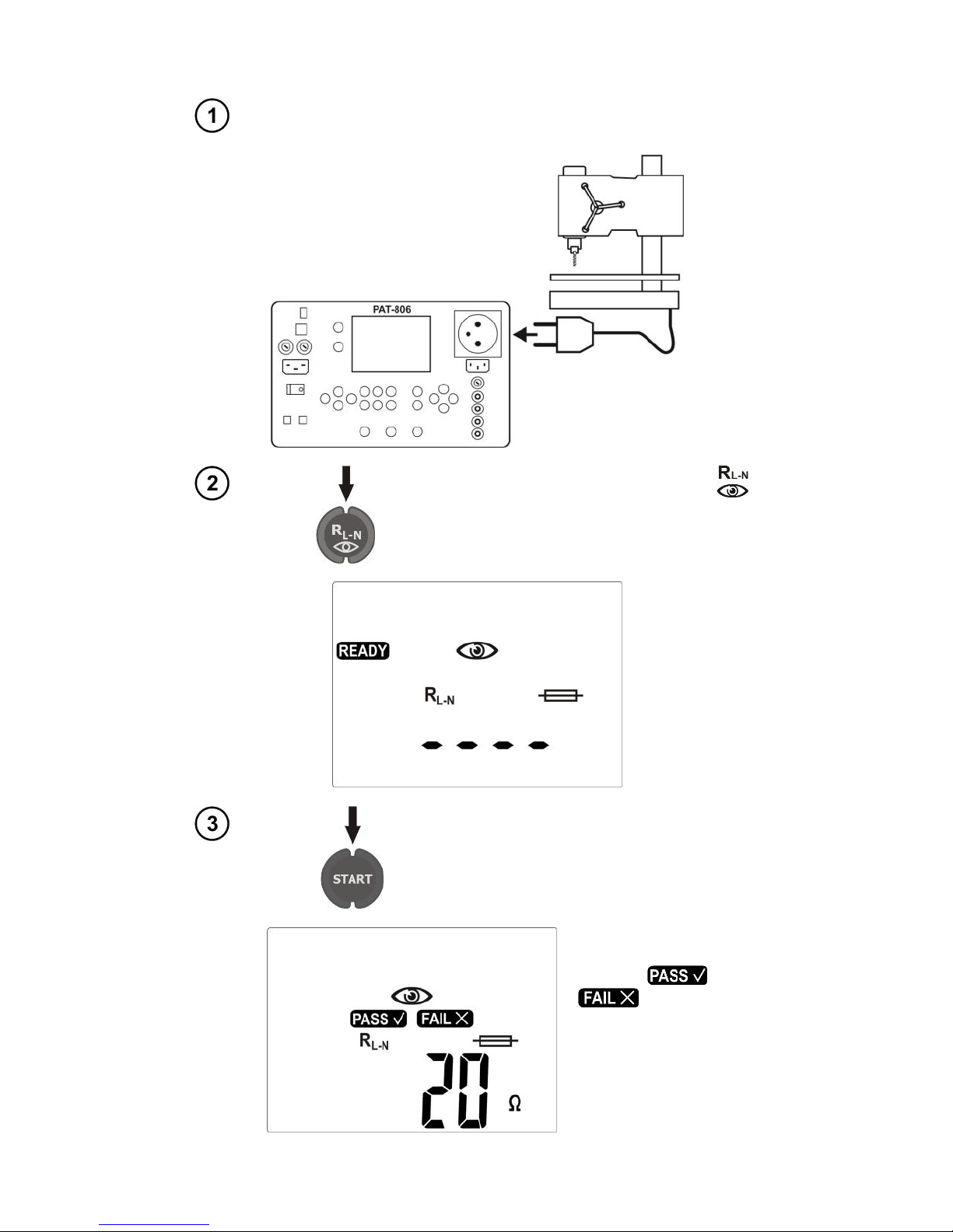
4.1 Preliminary test
Connect the mains plug of the tested device into the test
socket of the meter.
Press the button of initial measurement .
After that meter is prepared for measurement.
Press START.
Read the result.
Symbols and
are blinking.
Page 23
OPERATING MANUAL PAT-806 version 1.08
21
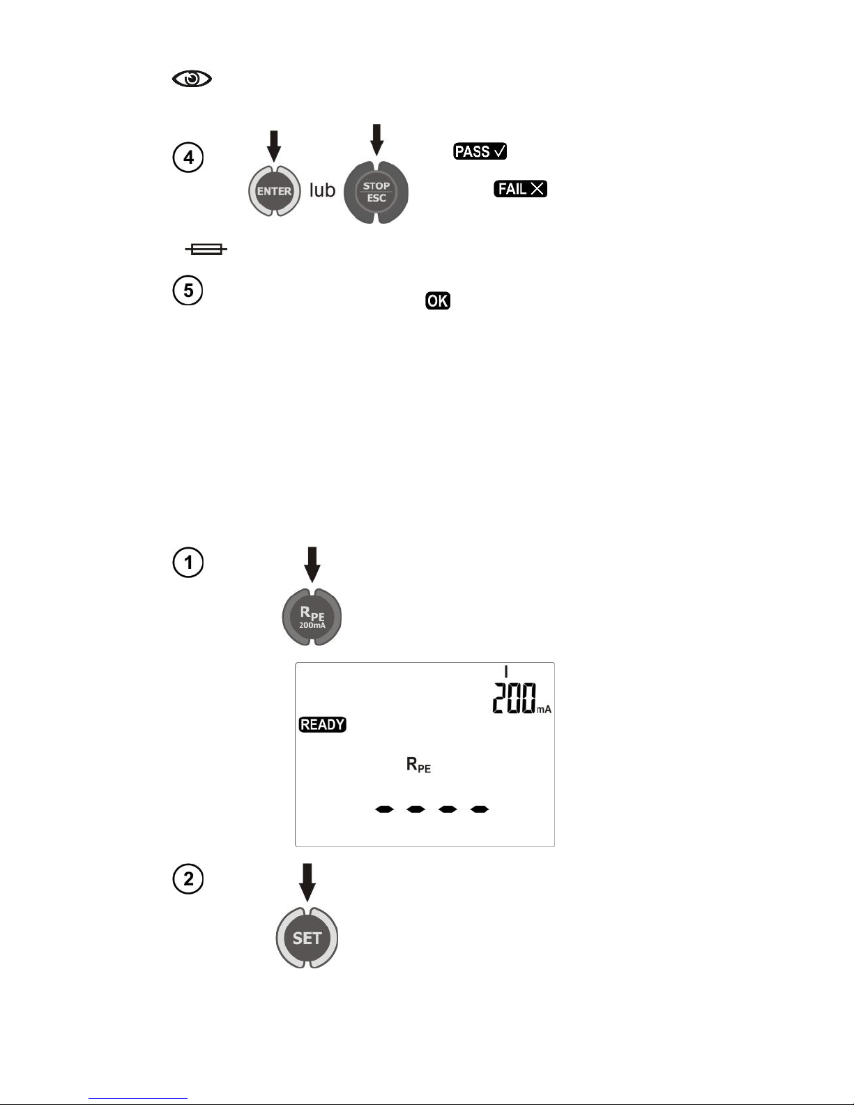
Symbol indicates the need for visual inspection on the tested device. Please check the
power cord insulation, quality of housing and mains plug (for cracks or damages) etc.
Press ENTER, if this test is successful ( is displayed) or
STOP/ESC, when the test result is
negative ( is displayed).
Symbol indicates the possibility to check the fuse removed from the tested device.
Contact the fuse with the test points. The efficiency of the fuse
is indicated by displaying and an acoustic signal.
Notes:
- Tested device must be turned on.
- R
L-N
measurement is intended for resistance objects, in case of inductive objects, the result may be
burdened with an additional errors.
- Fuse test is possible when READY message is displayed.
- Do not touch the two metal ends of the fuse with your fingers during the test, because a blown fuse
may be diagnosed as good.
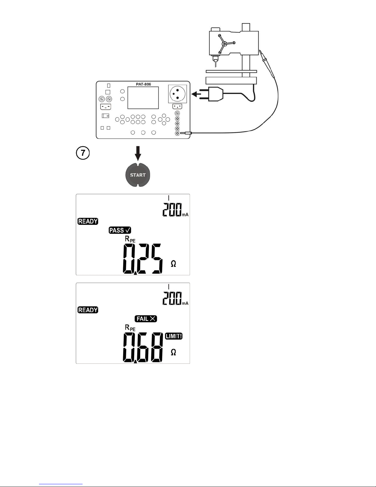
4.2 Measurement of protective lead resistance using 200 mA current
Keep pressing RPE button, until the screen informing about the readiness for measurement
with 200 mA current is displayed.
When parameters must be changed press
SET.
Page 24
OPERATING MANUAL PAT-806 version 1.08
22
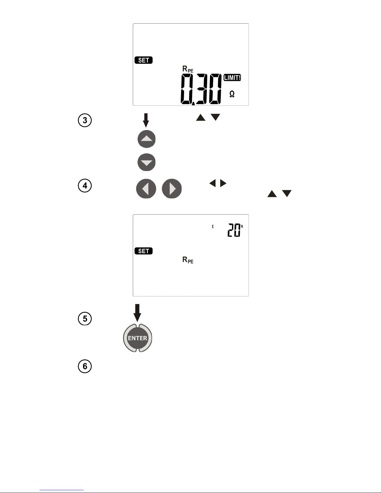
Use , to set the upper limit of RPE
resistance.
Use , to go to setting the time
of measurement, using , set
the measurement time.
Press ENTER to confirm the settings.
Connect the mains plug of the tested device into the test
socket of the meter. Use the probe connected to socket I2
and touch metal parts of the tested device connected to
PE.
Page 25
OPERATING MANUAL PAT-806 version 1.08
23
Press START.
After measuring is completed, read the result. The measurement may be stopped
before the set time runs out by pressing
STOP/ESC.
Correct result: RPE < LIMIT
Incorrect result: RPE > LIMIT
Notes:
- Tested device must be turned on.
- Test circuit is electrically isolated from the mains and from PE mains lead.
Page 26
OPERATING MANUAL PAT-806 version 1.08
24
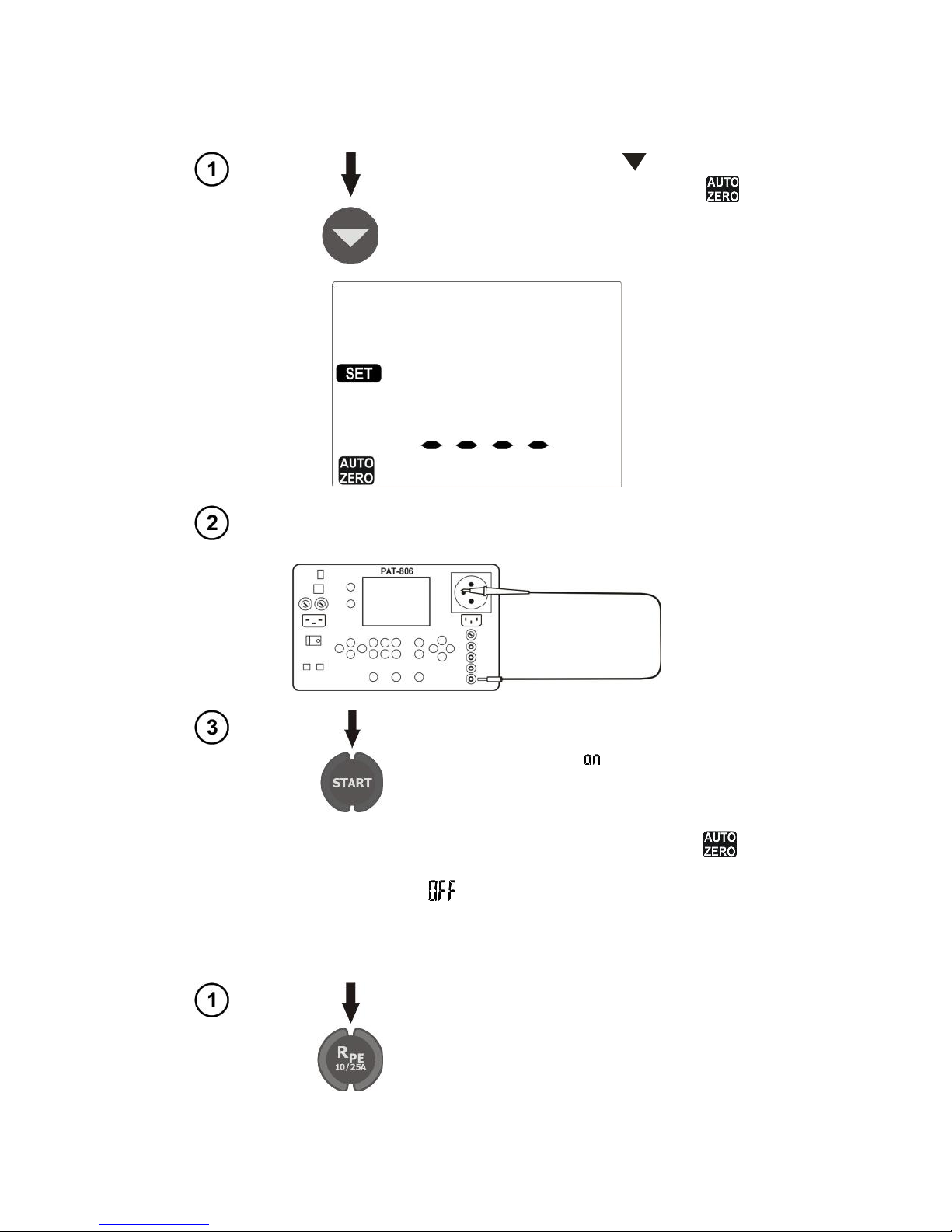
4.3 Compensation of the test lead resistance during the measurement of the protective lead resistance using 200 mA current (auto-zero)
In RPE 200mA mode, press . Auto-zero
screen will appear with blinking symbol .
Use the probe connected to I2 socket and touch PE pin of
the test socket.
Press START, to begin auto-zero.
After finishing auto-zero process, for 1s is
displayed message and the meter enters
the measuring function.
Completed auto -zero process is signalled during the measurement by displaying .
In order to remove auto-zero proceed in the same manner, but disconnect the test lead from PE.
After finishing, for 1s is displayed message .
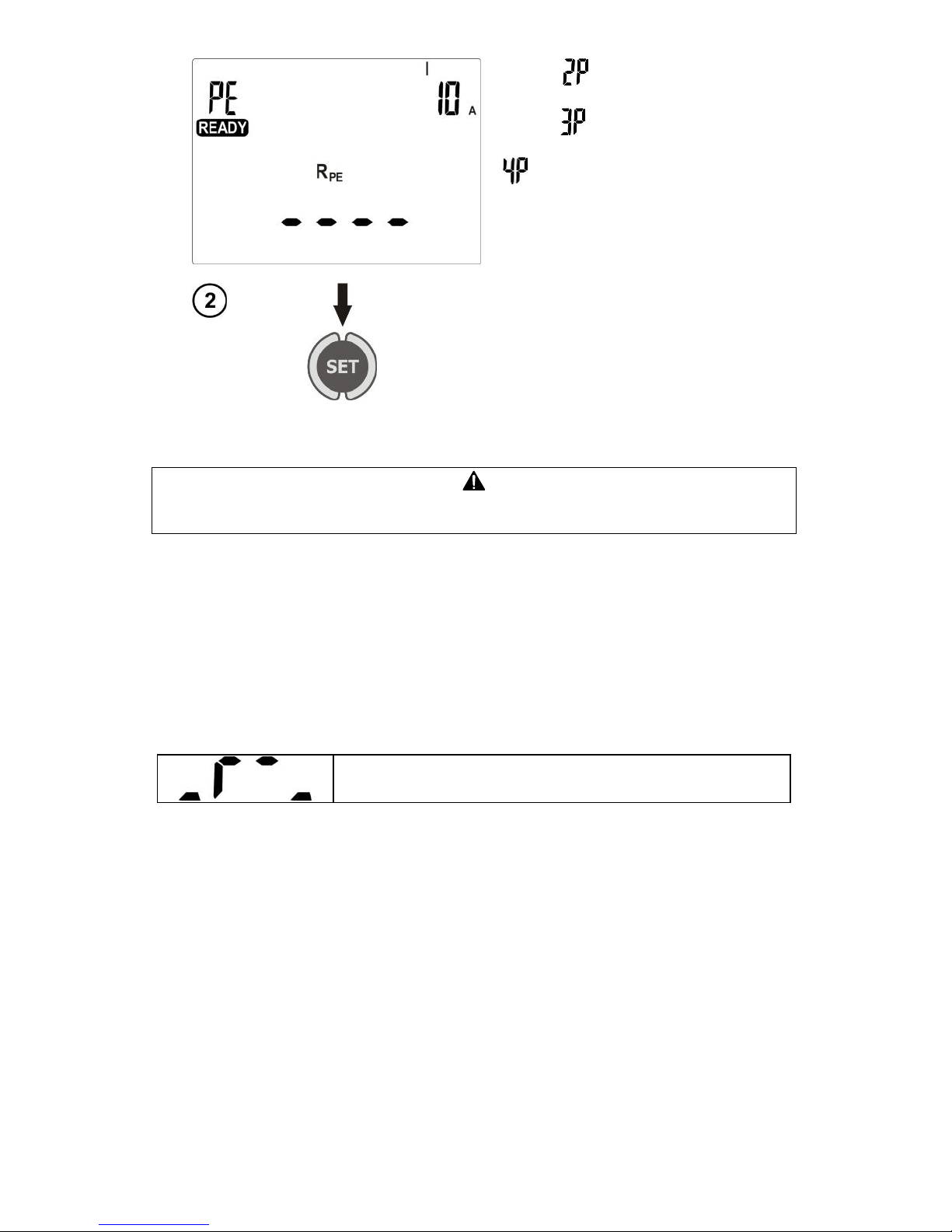
4.4 Measurement of protective lead resistance using 10/25 A current
Keep pressing RPE button, until the screen informing about the readiness for measurement
with desired current in desired configuration is
displayed.
Page 27
OPERATING MANUAL PAT-806 version 1.08
25
Symbol indicates that 10/25,
two-wire measurement is set,
symbol indicates that threewire measurement is set, symbol
indicates that four-wire measurement is set. Another pressing
of RPE results in switching current
values and measurement types.
When parameters must be changed press
SET. Setting is performed as in section 4.2.
Notes:
Note that any kind of adapter add extra resistance and thus the measurement
result will be overestimated.
- For 10 A and 25 A current, there is no possibility of continuous measurement settings (Cont.) If such
setting was set for the 200 mA current, then switching the meter to measure with 10/25 A current
causes that a default value of 5 s. is set as measuring time.
- To avoid excessive heating of the measuring pin in PE socket, do not trigger the measurement with
25 A current at short intervals.
- The method of measurement and other observations are the same as for the measurement of
200 mA.
Additional information displayed by the meter
Non-continuity in the test circuit during the measurement
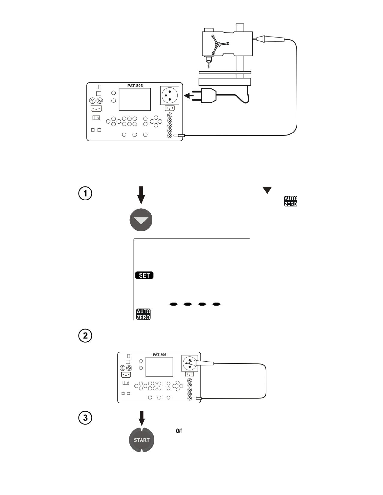
4.4.1 Two-wire measurement of protective lead resistance using 10/25 A
current
Connect the mains plug of the tested device into the test socket of the meter. Use the probe connected to socket I2 and touch metal parts of the tested device connected to PE.
Page 28
OPERATING MANUAL PAT-806 version 1.08
26
The method of measurement and observations are the same as for the measurement of 200mA.
4.4.2 Compensation of the test lead resistance during the measurement of
the protective lead resistance using 10 A or 25 A current (auto-zero)
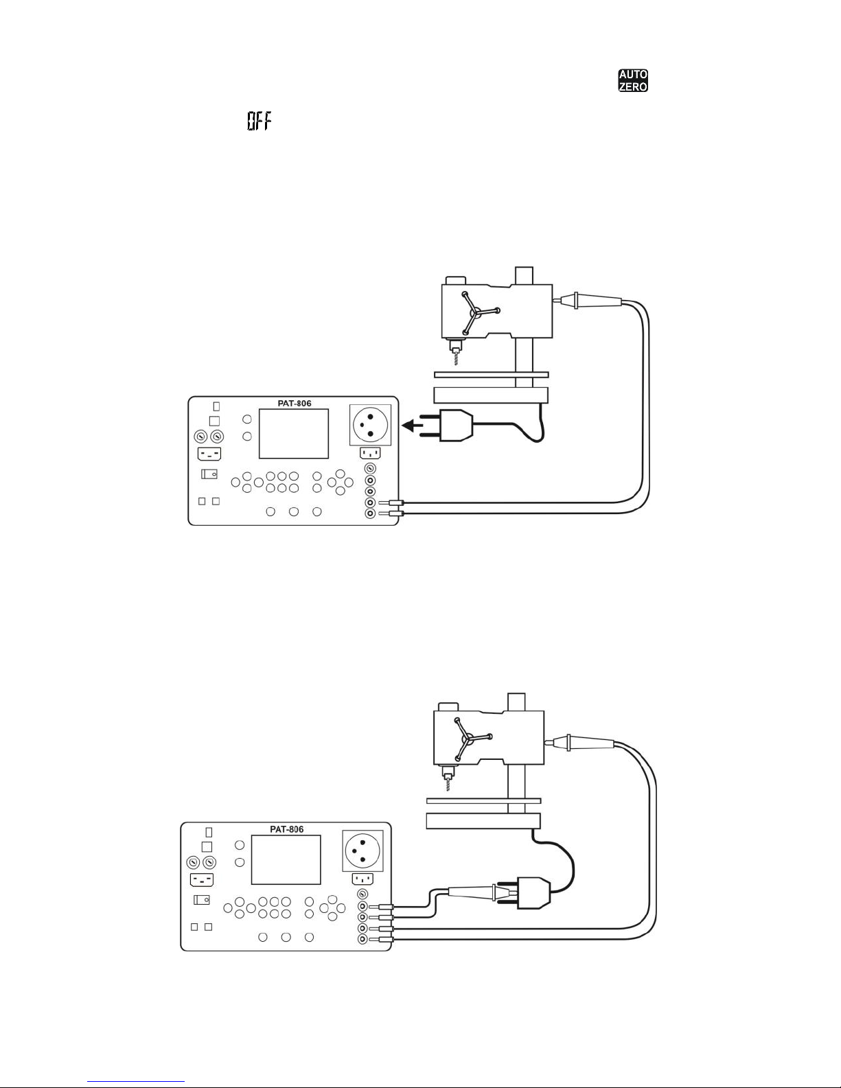
In RPE 10A or 25A mode, press . Auto-zero
screen will appear with blinking symbol .
Use the probe connected to I2 socket and touch PE pin of
the test socket.
Press START, to begin auto-zero.
After finishing auto-zero process, for 1s the
message is displayed and the meter en-
ters the measuring function.
Page 29
OPERATING MANUAL PAT-806 version 1.08
27
Completed auto -zero process during the measurement is signalled by displaying .
In order to remove auto-zero proceed in the same manner, but disconnect the test lead from PE.
After finishing for 1s the message is displayed.
4.4.3 Three-wire measurement of protective lead resistance using 10/25 A
current
Connect the mains plug of the tested device into the test socket of the meter. Use the power probe (or Kelvin crocodile clip) connected to U2 and I2
sockets and touch metal parts of the tested device connected to PE.
The method of measurement and observations are the same as for the measurement of 200 mA.
4.4.4 Four-wire measurement of protective lead resistance using 10/25 A
current
Connect one probe (or crocodile clip) connected to I1, U1 sockets, to PE of
power cable of the tested device. Use the power probe (or Kelvin crocodile
clip) connected to U2 and I2 sockets and touch metal parts of the tested device connected to PE.
The method of measurement and observations are the same as for the measurement of 200 mA.
Page 30
OPERATING MANUAL PAT-806 version 1.08
28
4.5 Measurement of insulation resistance
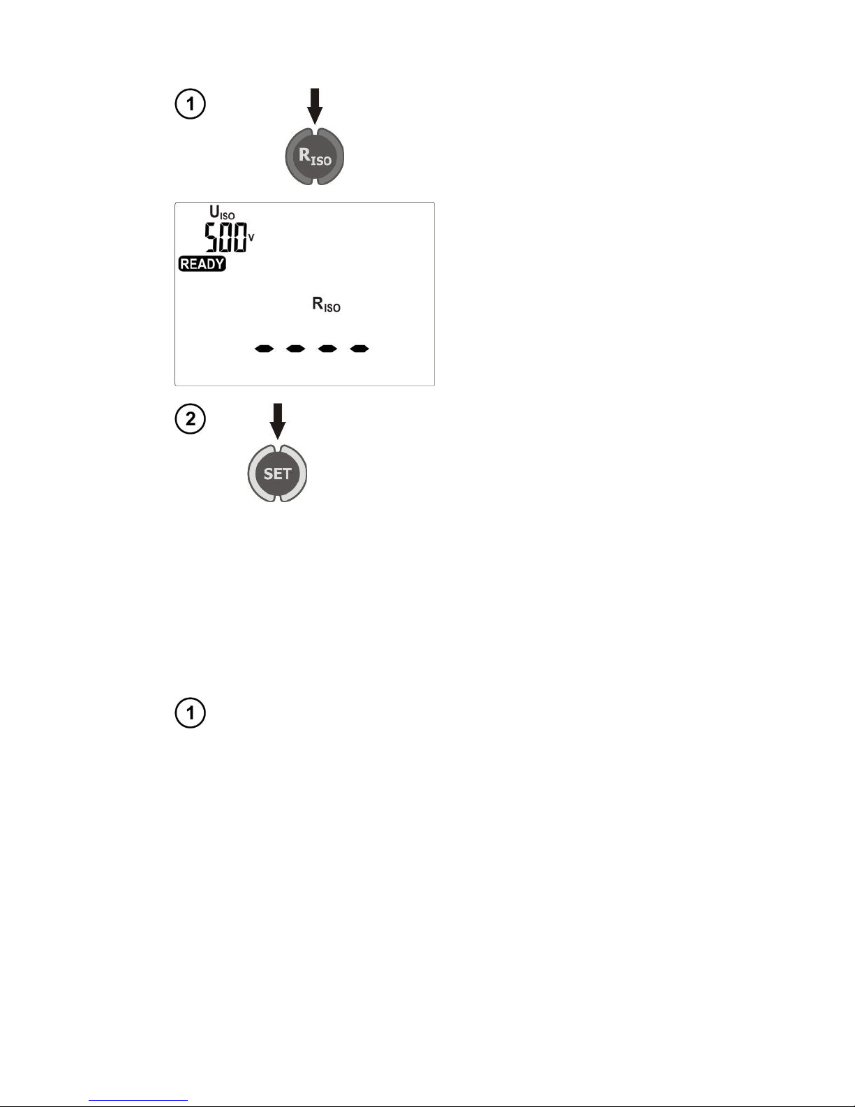
Press R
ISO
. After that meter is prepared for
measurement.
Further pressing of R
ISO
results in
switching from standard R
ISO
measurement to a three-point
measurement on welding equipment.
When parameters must be changed press SET.
Setting is performed as in section 4.2 (lower limit is
set). For the standard measurement the following
parameters are set: U
ISO
voltage, the lower limit
value and measurement time. For the triple measurement U
ISO
voltage is set for all three measurements as well as limits and measurement times for
each measurement.
Notes:
- Tested device must be turned on.
- Test circuit is electrically isolated from the mains and from PE mains lead.
- The measurement result should be read after displayed values are stabilized.
- After the measurement the tested object is automatically discharged.
4.5.1 R
ISO
measurement on devices of Class I
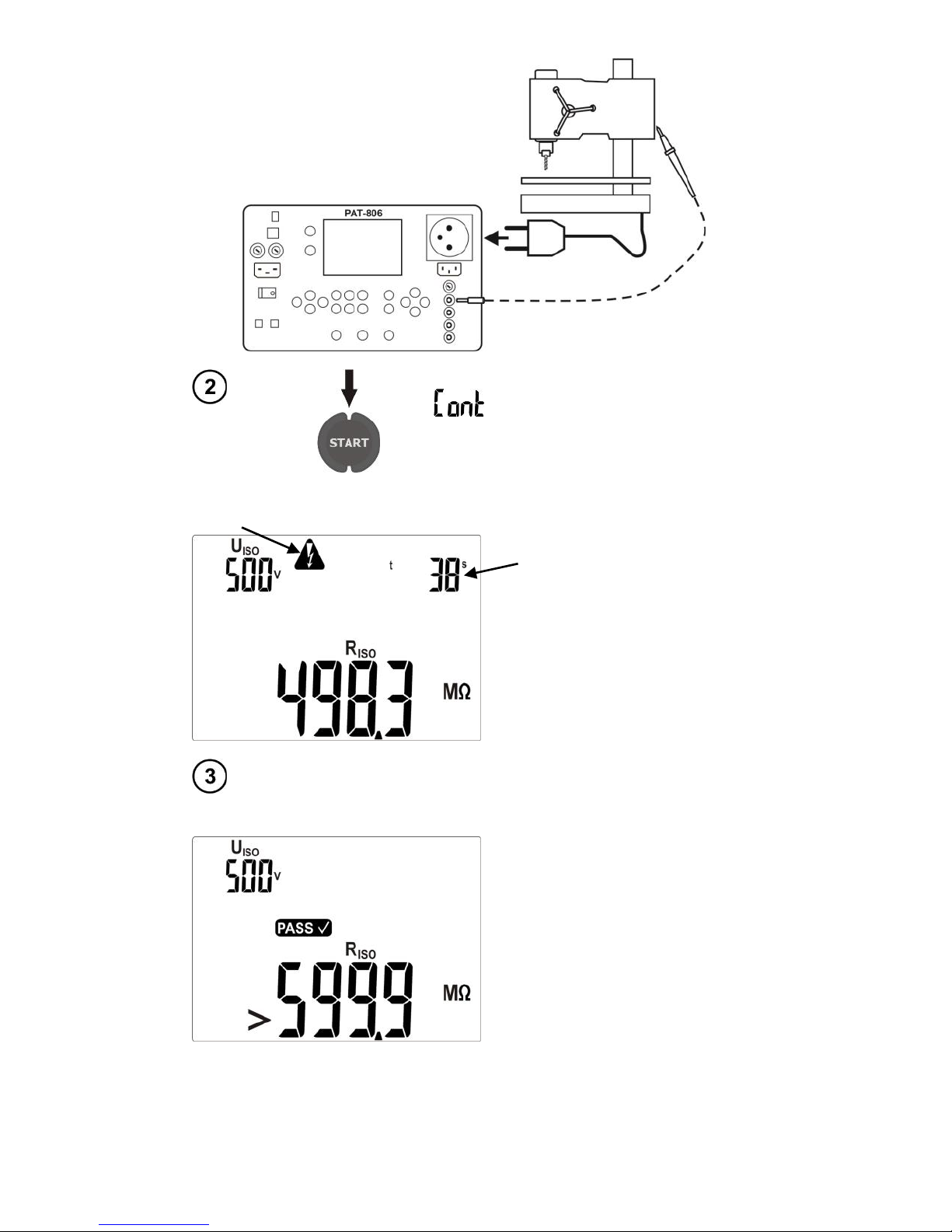
Connect the mains plug of the tested device into the test socket
of the meter. The measurement is made between shorted L, N
and PE. In addition, it is possible to carry out the measurement
with the probe connected to R
ISO
- socket.
Page 31
OPERATING MANUAL PAT-806 version 1.08
29
With continuous measurement set (time =
) press and hold START. To block
the measurement press ENTER.
At the time with pre-set value it is not necessary.
Signalling the presence of high-voltage
View of the screen during
measurement.
Time remaining to the end of
the measurement
The measurement ends after a preset time runs out or
after pressing STOP/ESC.
After measuring is completed, read the result.
Correct result: R
ISO
> LIMIT
Page 32
OPERATING MANUAL PAT-806 version 1.08
30
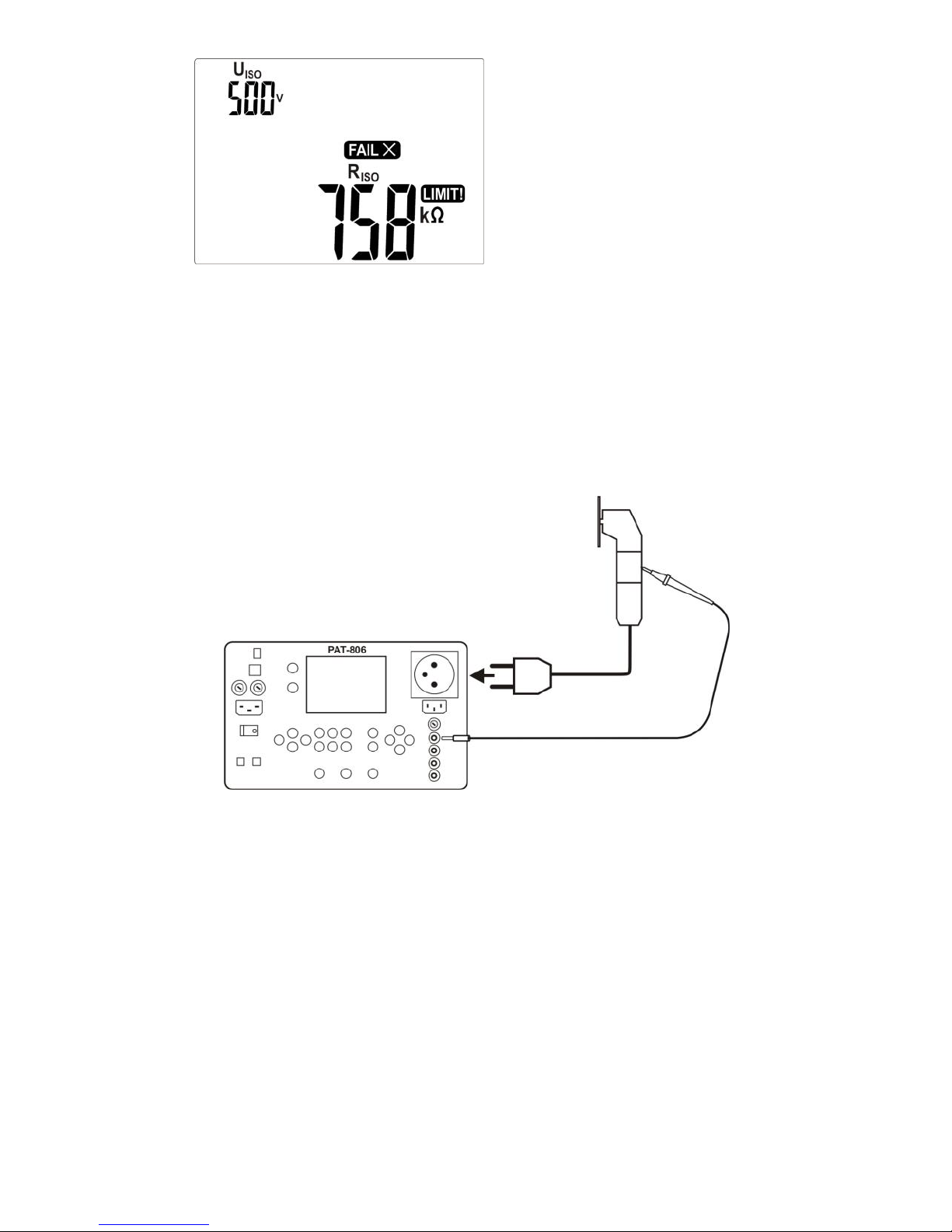
Incorrect result: R
ISO
< LIMIT
Notes:
- Before the measurement (also in AUTO test) check the resistance of the protective conductor RPE,
which should be correct.
4.5.2 R
ISO
measurement on devices of Class II (III)
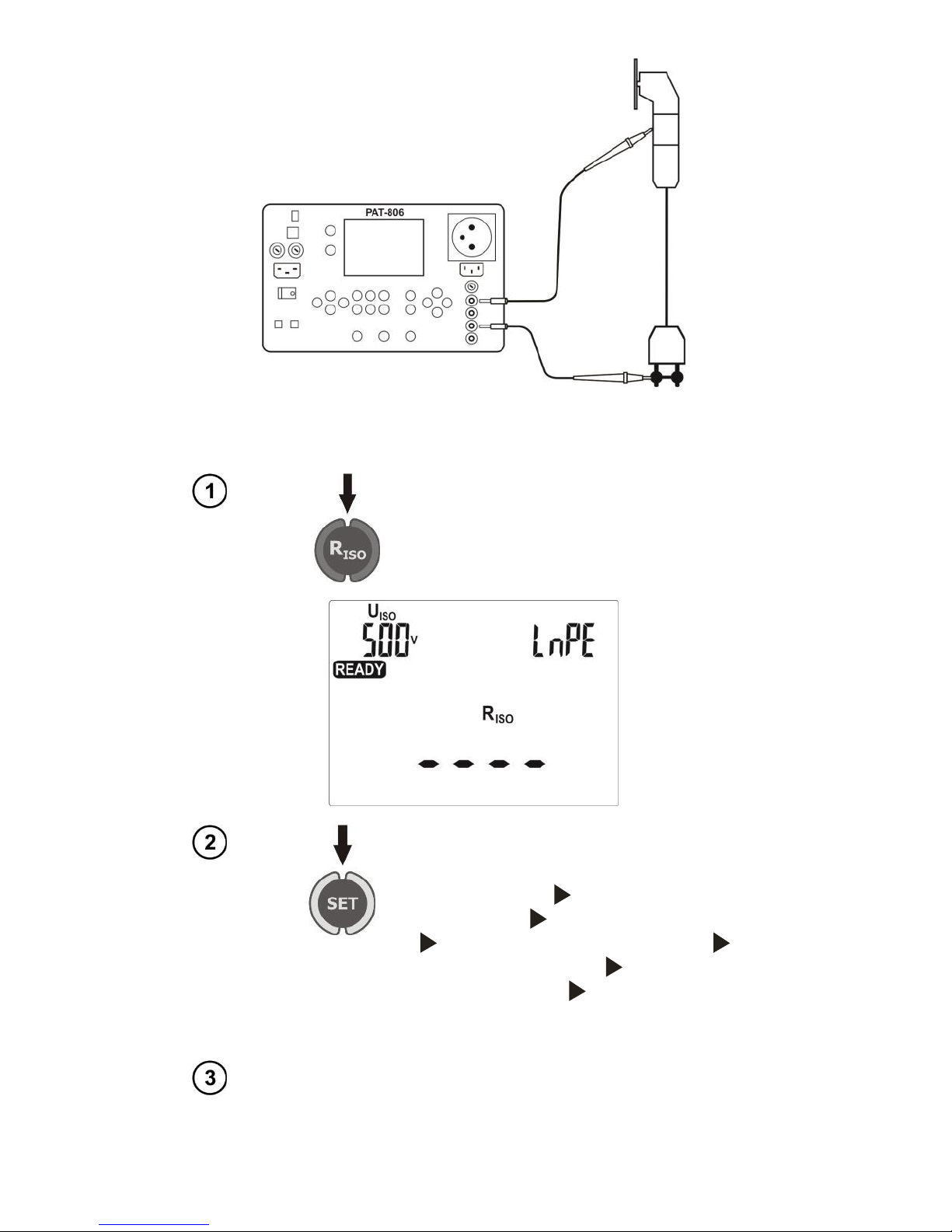
Connect the mains plug of the tested device into the test socket of the meter. L and N are shorted. Use the probe connected to socket R
ISO
- and touch
the conductive accessible parts of the tested device.
It is also possible to perform measurement without the test socket - by using
the following sockets: R
ISO
- and R
ISO
+.
Page 33
OPERATING MANUAL PAT-806 version 1.08
31
The measurement is performed similarly as in 4.5.1.
4.5.3 Three-point R
ISO
measurement on welding equipment
Keep pressing R
ISO
button, until the screen informing about the readiness for measurement
is displayed.
When parameters must be changed press
SET. Setting is performed as in section 4.2.
Measurement parameters are set in the fol-
lowing order: U
ISO
a limit value for LN-PE
measurement
LN-PE measurement time
a limit value for LN-S measurement
LN-S measurement time a limit value for
PE-S measurement PE-S measurement
time, where S means shorted outputs of the
welding machine.
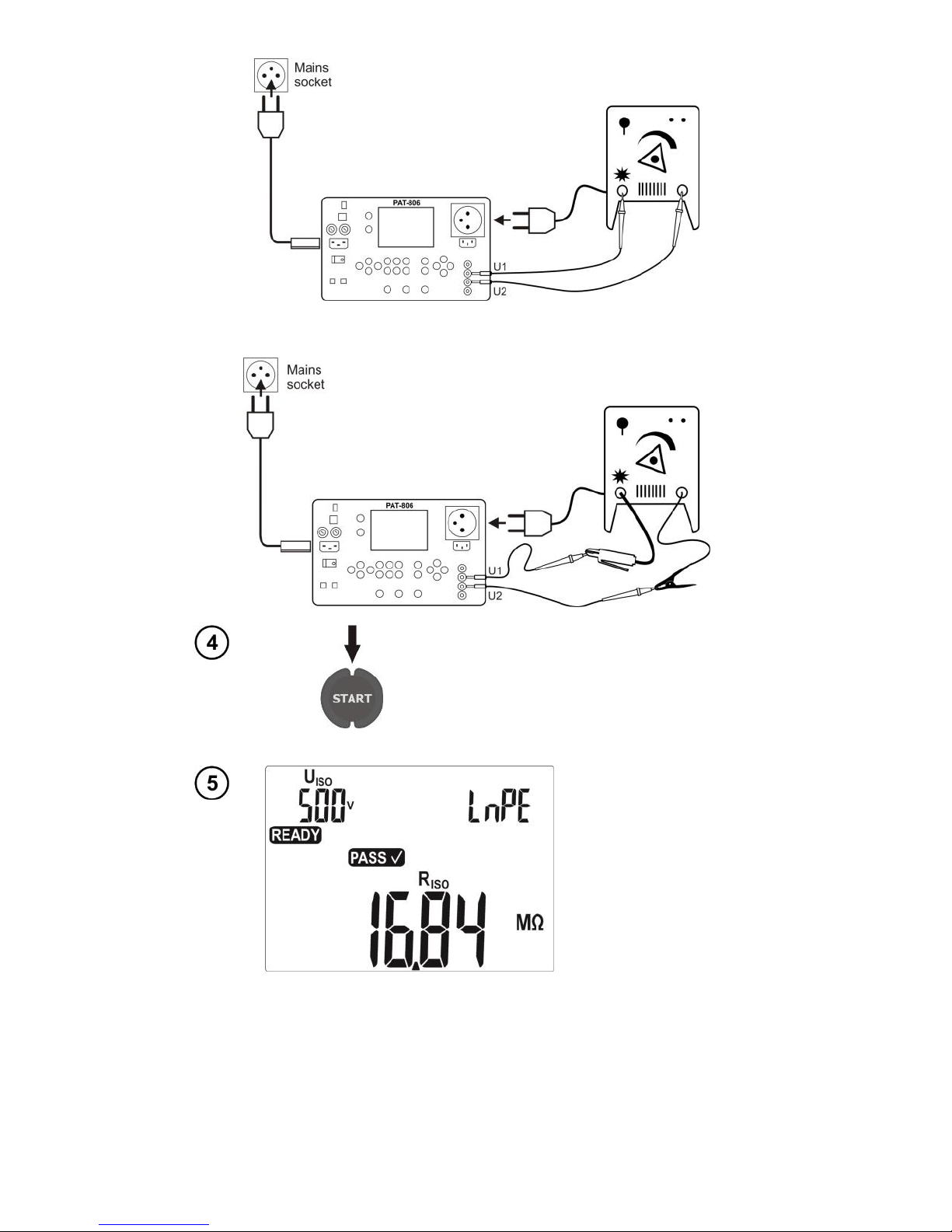
Connect the socket plug of the tested device into the test socket of the meter, whereas the outputs to U1 and U2 sockets of
the meter.
Page 34
OPERATING MANUAL PAT-806 version 1.08
32
or additionaly:
Press START button to start the measure-
ments that are executed automatically one
after the other.
The final measurement
result for all resistances
above the limit values
are shown below.
Page 35
OPERATING MANUAL PAT-806 version 1.08
33
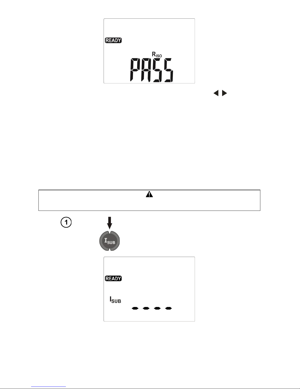
Individual results and measurement parameters may be browsed with buttons , .
Notes:
- Pressing STOP/ESC button, when the result is displayed, stops the measurement with the current
result and puts the meter into the readiness mode - the next measurement may be started by pressing START button.
Pressing STOP/ESC button, when horizontal lines are displayed, results in stopping the measurement. Press START button to re-start the measurement.
- In order to avoid the consequences of accidental connecting the welding machine plug into a power
socket, the outputs of the welding machine are shorted by 10 kΩ resistance and this value is negligible when compared to the typical values of insulation resistance.
4.6 Measurement of substitute leakage current
I
SUB
current is measured at 25 V...50 V voltage and its value is rescaled to the nominal
mains voltage set in menu (see 3.3.7).
Press I
SUB
. After that meter is prepared for
measurement.
Page 36
OPERATING MANUAL PAT-806 version 1.08
34
When parameters must be changed press
SET. Setting is performed as in section 4.2.
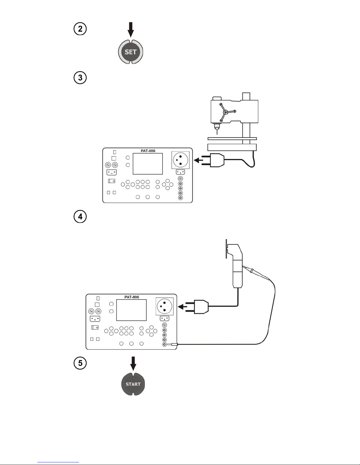
For Class I, connect the mains plug of the tested device into
the test socket of the meter.
For Class II and for accessible parts not connected to PE in
Class I, additionally connect I2 socket to the probe which will
be used for touching accessible parts of the tested device.
Press START.
After measuring is completed, read the result. The measurement may be stopped
before the set time runs out by pressing
STOP/ESC.
Page 37
OPERATING MANUAL PAT-806 version 1.08
35
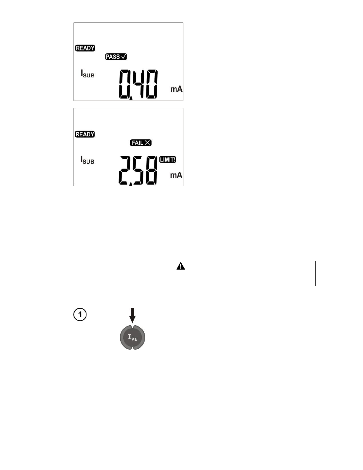
Correct result: I
SUB
< LIMIT
Incorrect result: I
SUB
> LIMIT
Notes:
- Tested device must be turned on.
- Test circuit is electrically isolated from the mains and from PE mains lead.
- Test voltage is 25 V ... 50 V rms
4.7 Measurement of PE leakage current
It is recommended for checking the welding equipment to use the measurements: the
leakage current of the primary circuit and leakage current welding circuit.
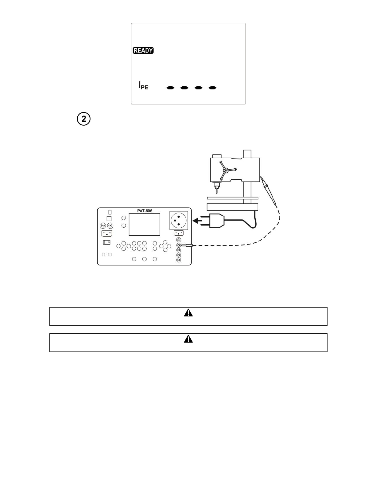
Press IPE. After that meter is prepared for
measurement.
Page 38
OPERATING MANUAL PAT-806 version 1.08
36
Connect the mains plug of the tested device into the test socket
of the meter. The measurement is made between shorted L, N
and PE. In addition, it is possible to carry out the measurement
with the probe connected to R
ISO
- socket.
Settings and the measurement are as in 4.5.1.
Notes:
During the measurement in the test socket the voltage of mains is present.
During the measurement of a faulty device, RCD switch may be triggered off.
- PE leakage current is measured directly on this line enabling the user to get precise measurement
results even when the device consumes 10 A or 16 A current. Note that if the current leakage is not
caused by PE line but by other earthed elements (e.g. water pipe) – it cannot be measured in this
measurement function. Then, it is recommended to perform a differential measurement of leakage
current.
- Ensure that the location of the tested device is isolated.
- Tested device must be turned on.
- In the half-time of the measurement, the meter automatically changes the polarity of the test socket
and as a result it displays the value of higher leakage current.
Page 39
OPERATING MANUAL PAT-806 version 1.08
37
4.8 Measurement of differential leakage current
It is recommended for checking the welding equipment to use the measurements: the
leakage current of the primary circuit and leakage current welding circuit.
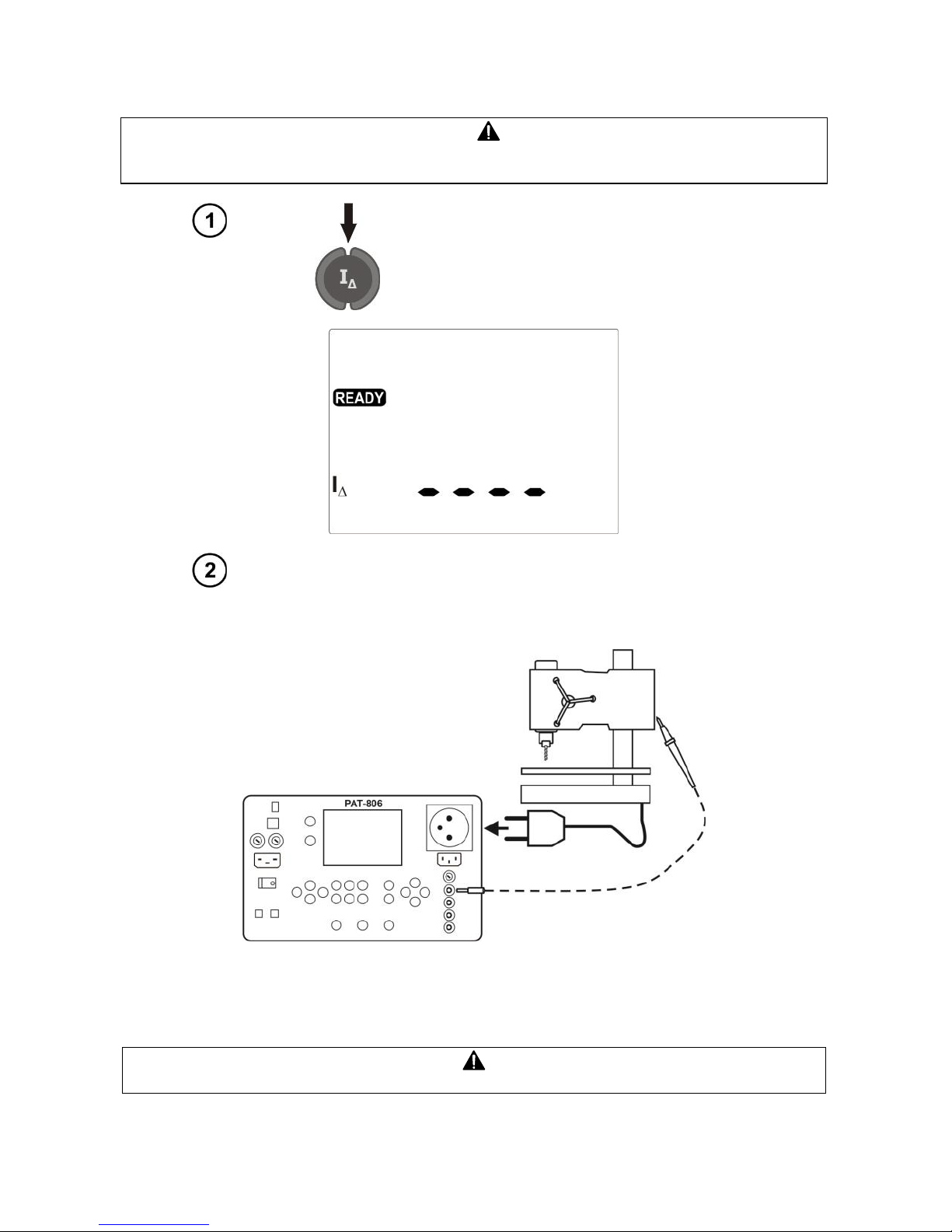
Press I∆. After that meter is prepared for
measurement.
Connect the mains plug of the tested device into the test socket
of the meter. The measurement is made between shorted L, N
and PE. In addition, it is possible to carry out the measurement
with the probe connected to R
ISO
- socket.
Settings and the measurement are as in 4.5.1.
Notes:
During the measurement in the test socket the voltage of mains is present.
Page 40
OPERATING MANUAL PAT-806 version 1.08
38
During the measurement of a faulty device, RCD switch may be triggered off.
- Differential leakage current is measured as a difference between L current and N current. This
measurement takes into account not only PE leakage current, but also leakage currents caused by
other earthed elements - e.g. water pipe. The disadvantage of this measurement is the influence of
the common current value (flowing to the tested device through line L and returning through line N) on
the accuracy of the measurement. If this current is high, the measurement will be less accurate (as
described in the technical data) than the measurement of PE leakage current.
- Tested device must be turned on.
- In the half-time of the measurement, the meter automatically changes the polarity of the test socket
and as a result it displays the value of higher leakage current.
- The result of measurement may be affected by the presence of external fields and by the current
used by the device.
Note:
The differential method of leakage current measurement is permitted by EN 60974-4
standard as an alternative for measuring the primary leakage current performed during
periodic tests of welding equipment.
4.9 Measurement of touch leakage current
It is recommended for checking the welding equipment to use the measurements: the
leakage current of the primary circuit and leakage current welding circuit.
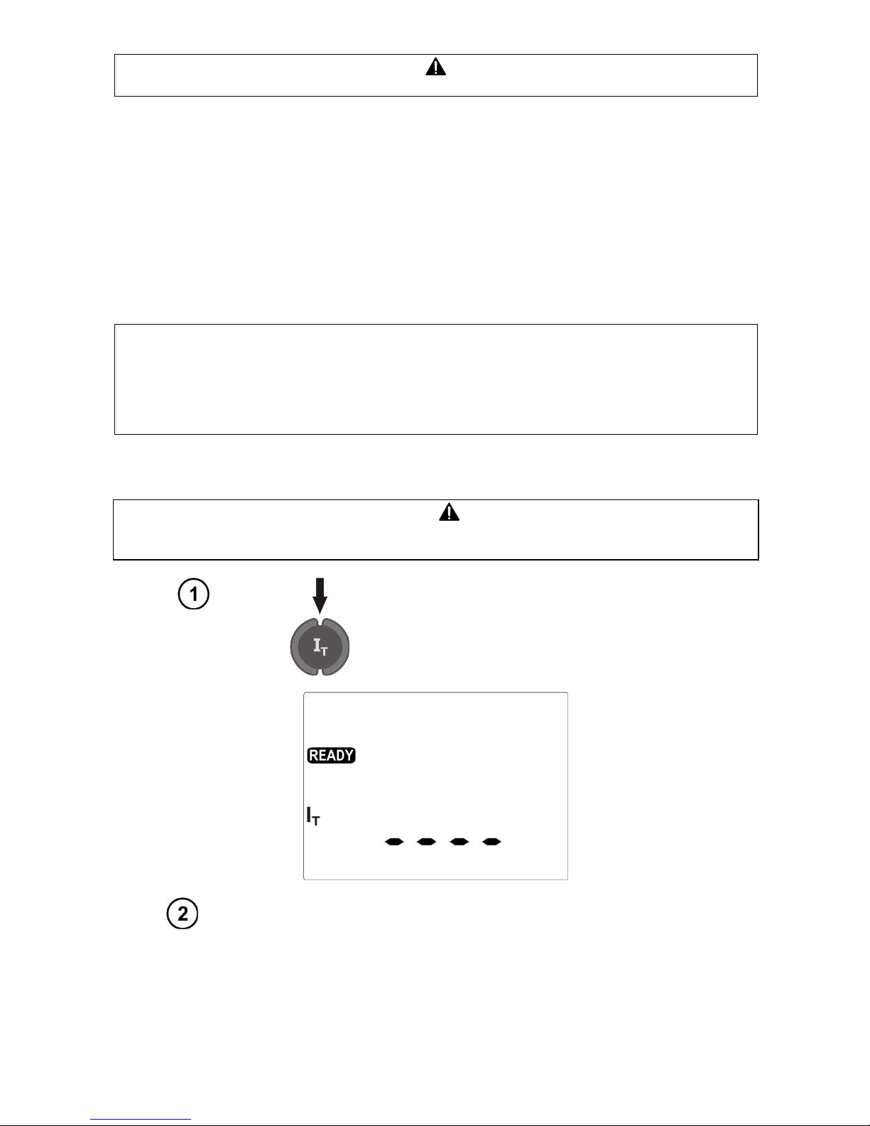
Press IT. After that meter is prepared for
measurement.
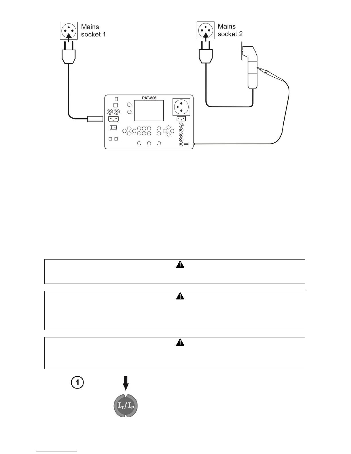
Supply the tested device from mains socket other than PAT (for
Class I the socket must have PE). Additionally connect the probe
which will be used for touching accessible parts of the tested device (for parts of Class I accessible and not connected to PE).
Page 41
OPERATING MANUAL PAT-806 version 1.08
39
Settings and measurements as in section 4.5.
Notes:
- The measurement should be performed at both positions of the mains plug of the tested device and
as the result the higher current value should be accepted.
- The bandwidth of test current results from the measuring system with adjusted touch current which
simulates human perception and reaction, in accordance with EN 60990: 2002.
4.10 Measurement of leakage current in the primary circuit of the
welding machine using PAT IP adapter
Before performing the measurement, read the manual provided with PAT-IP adapter.
Following measurement method is recommended to check the welding machines (in
accordance with PE-EN 60974-4 standard).
The adapter may be used only with PAT-806 device to measure the leakage current in
the welding machine primary circuit. Any application that differs from those specified
in the present manual may result in danger to the user. Do not use the adapter as an
extension cord. Do not use the adapter for power measurements.
During the measurements performed on the welding circuit of the welding machine, the
high-voltage contactless module used for igniting /arc sustaining (ionizer, HF), if present, should be disconnected or switched off.
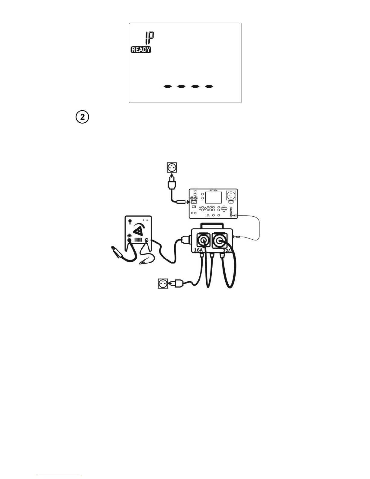
Press once or twice IT/IP button to display
the below screen indicating that the device is
ready for measurements.
Page 42
OPERATING MANUAL PAT-806 version 1.08
40
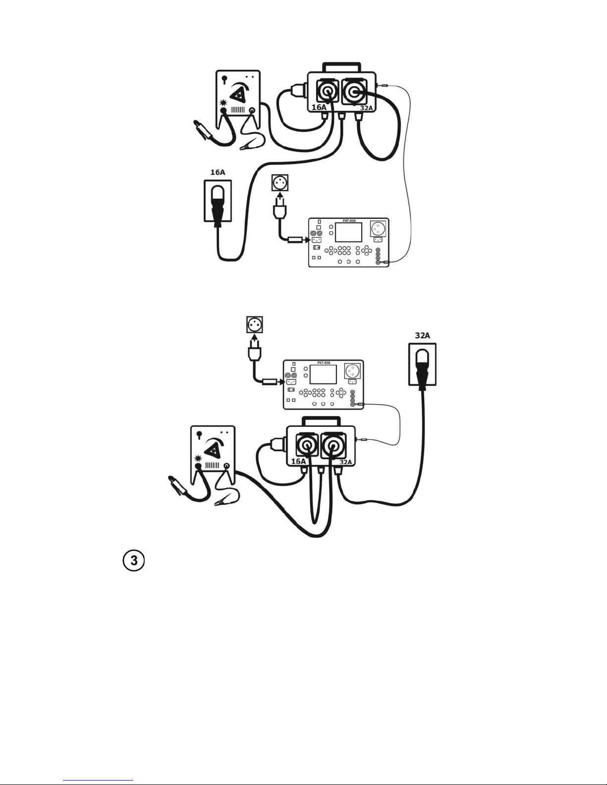
Depending on the type of power supply provided to the welding
machine - apply one of the following diagrams. Unused leads
must be plugged into appropriate sockets. Connect the banana
socket of the adapter to I2 socket of PAT-806.
Power supply from 230 V mains
Mains
socket
Mains
socket
Page 43
OPERATING MANUAL PAT-806 version 1.08
41
Three-phase power supply (16 A)
Three-phase power supply (32 A)
The measurement ends after the preset time runs out or after
pressing STOP/ESC.
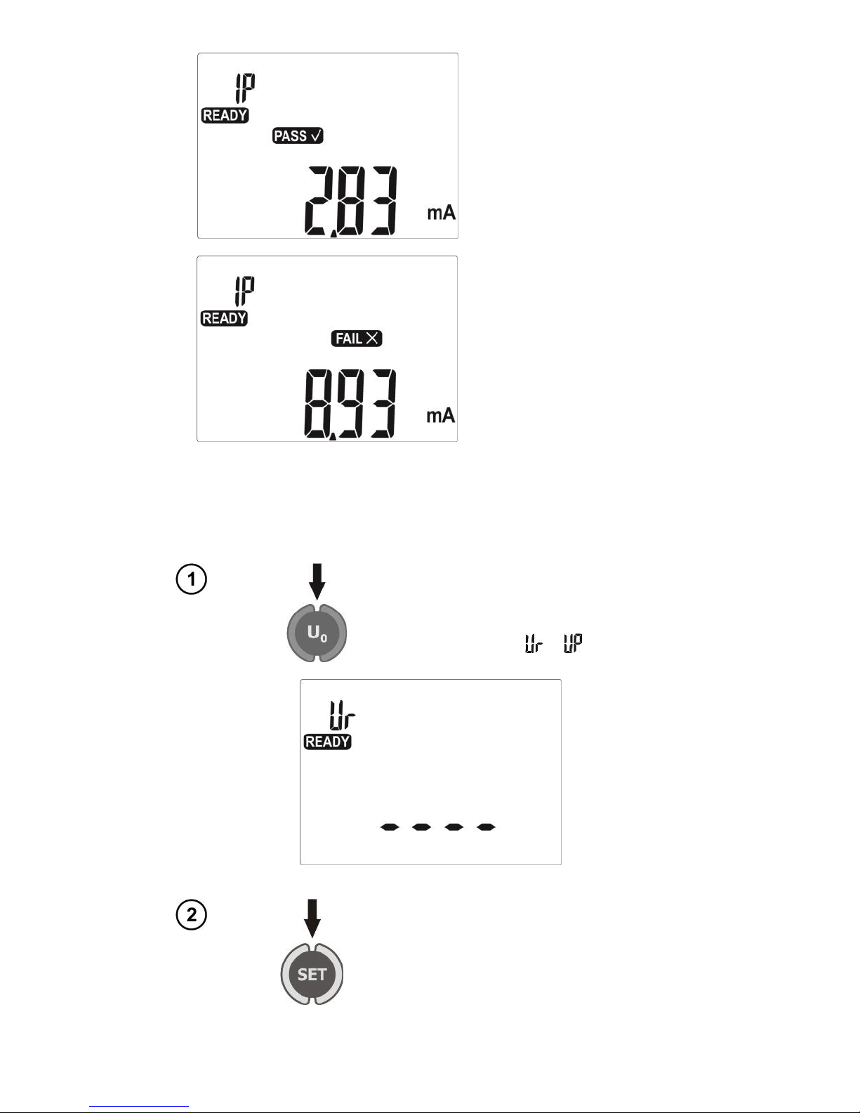
After the measurement is completed, read the result.
Mains
socket
Mains
socket
Page 44
OPERATING MANUAL PAT-806 version 1.08
42
Correct result: IP < LIMIT
Incorrect result: IP > LIMIT
Settings and measurements as in section 4.5.1.
4.11 Rated voltage measurement on welding equipment without
load
Press U0 button once or twice depending on
chosen voltage measurement: r.m.s. Ur voltage or UP peak voltage. The screen informing
about the readiness for measurement will be
displayed with symbol or .
When the limit value must be changed press
SET.
Page 45
OPERATING MANUAL PAT-806 version 1.08
43
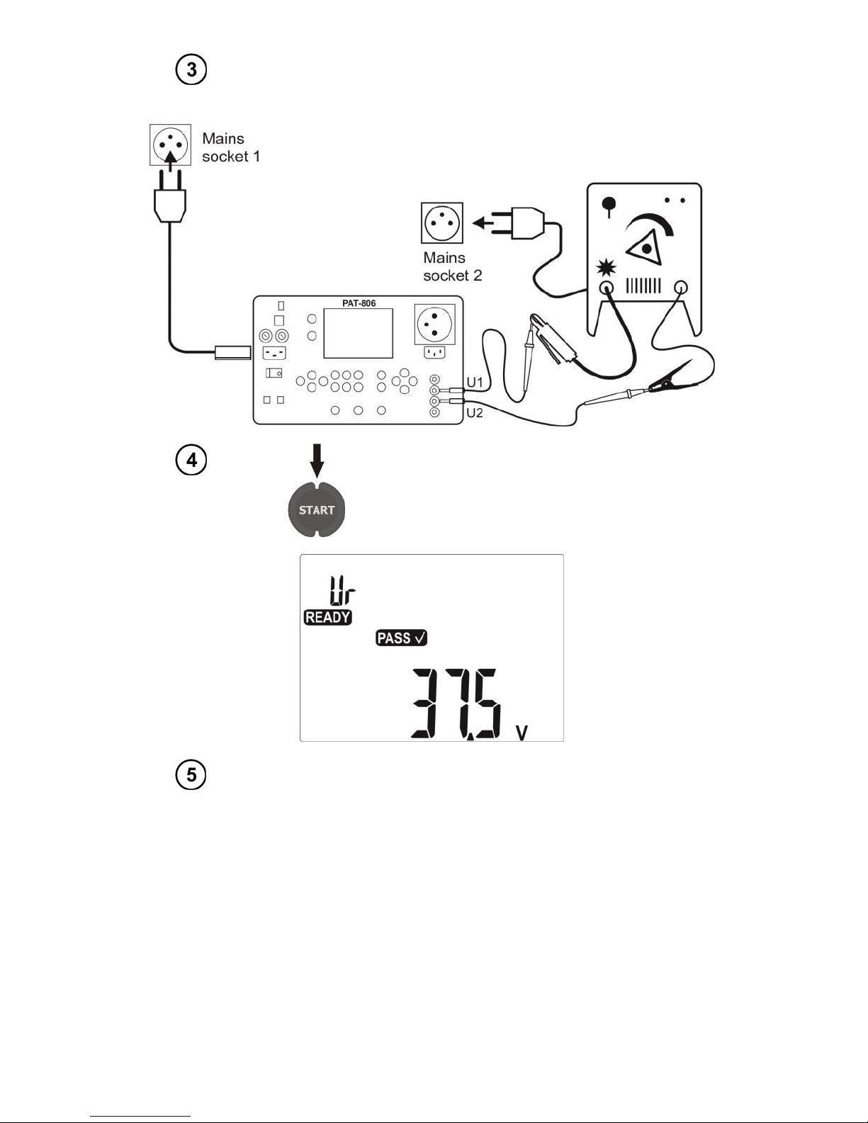
Connect the power plug of the tested welding machine to the
mains socket, other than PAT. Connect the outputs of the welding machine to U1 and U2 sockets of the meter.
Press START. After the measurement is completed, read the result.
Perform the measurement for Ur and UP
Notes:
- During the measurement of r.m.s. voltage, the tested welding machine is loaded with 5 kΩ resistance, as defined in EN 60974-4.
- During the measurement of peak voltage the tested welding machine is loaded with the resistance
varying in the range of 200 Ω...5 kΩ, as defined in EN 60974-4. Positive and negative peak values
are measured and the highest measured value is displayed.
- Tested device must be turned on.
- The measuring time is not set.
Page 46
OPERATING MANUAL PAT-806 version 1.08
44
4.12 Leakage current measurement on welding circuit IL
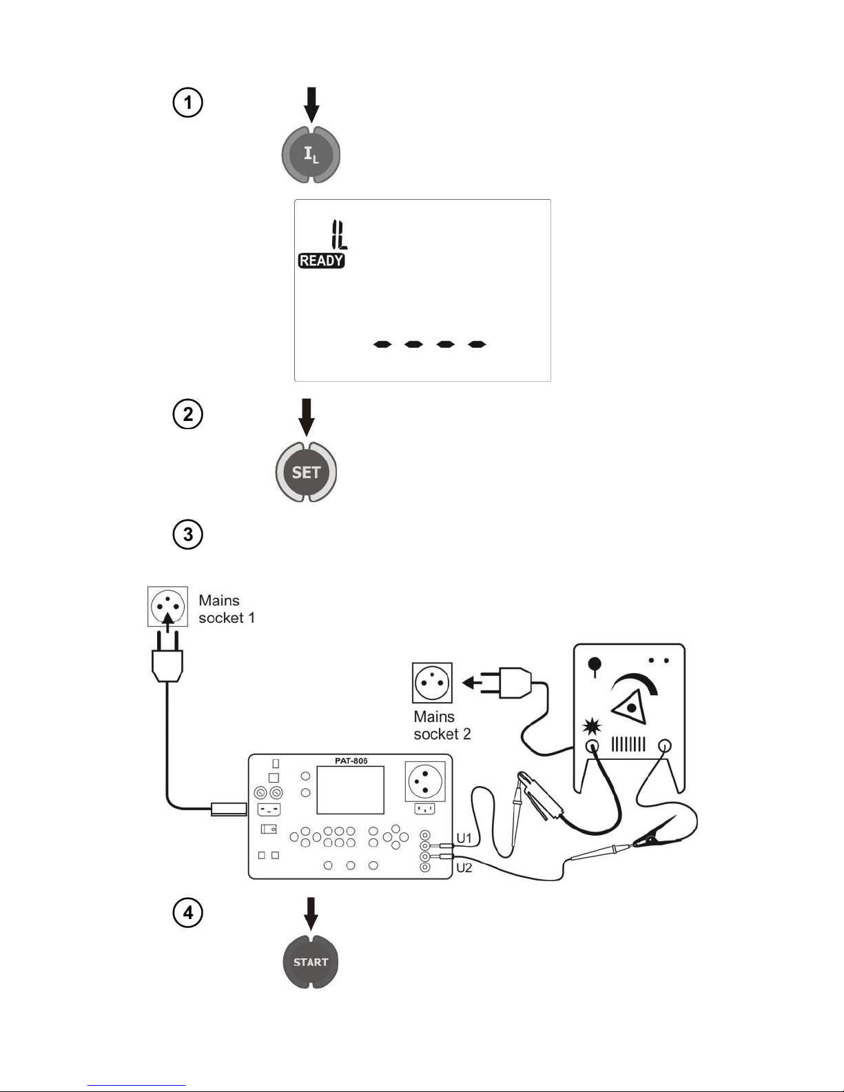
Press IL. The screen informing about the readiness for measurement will be displayed.
When parameters must be changed press
SET (upper limit value and the measurement
time are set).
Connect the power plug of the tested welding machine to the
mains socket, other than PAT. Connect the outputs of the welding machine to U1 and U2 sockets of the meter.
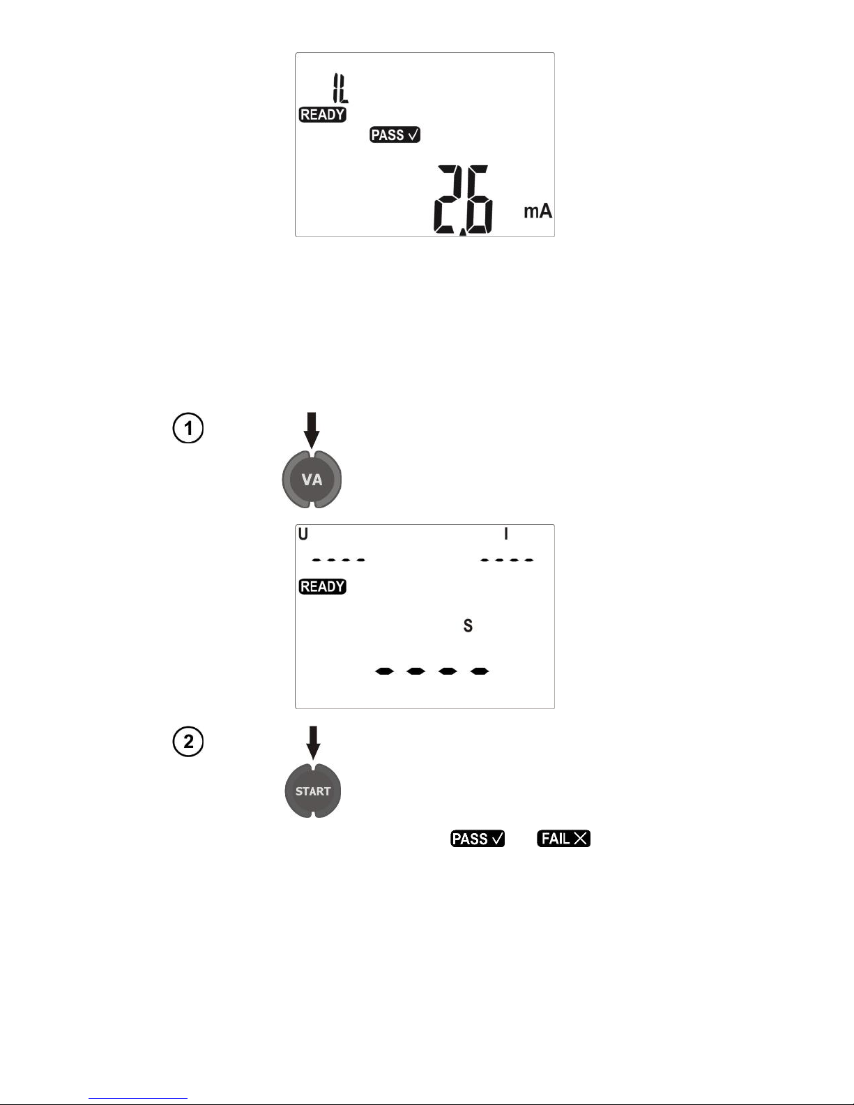
Press START. After the measurement is completed, read the result. The measurement may
be stopped by pressing STOP/ESC button.
Page 47
OPERATING MANUAL PAT-806 version 1.08
45
Notes:
- The measurement is performed in two stages: IL leakage current is measured successively for both
welding machine outputs and the higher value is displayed.
- Tested device must be turned on.
- The measurement is in compliance with EN 60974-4.
4.13 Measurement of current, power consumption and voltage
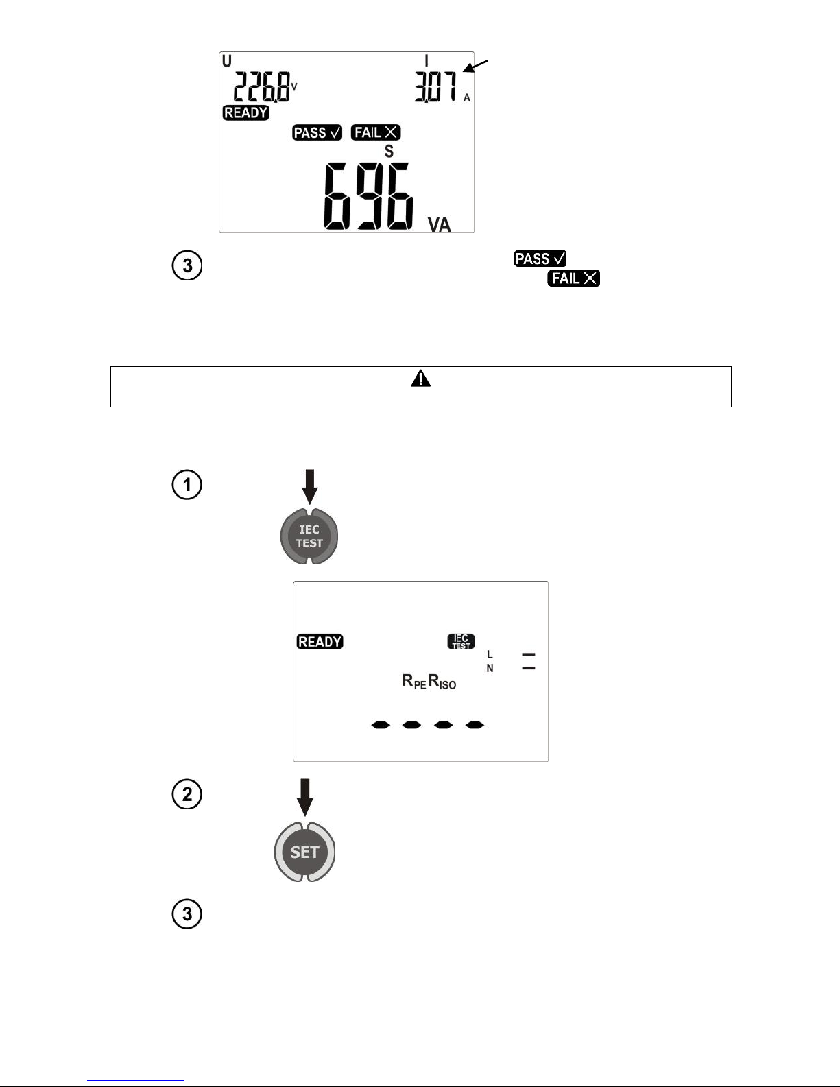
Press VA. After that meter is prepared for
measurement.
Press START.
The measurement may be stopped before
the set time runs out by pressing
STOP/ESC.
After measuring is completed, read the result.
Symbols and are blinking.
Page 48
OPERATING MANUAL PAT-806 version 1.08
46
During the measurement
current I is displayed alternatively with the time of
measurement.
Press ENTER, if this test is successful ( is displayed) or
STOP/ESC, when the test result is negative ( is dis-
played).
Notes:
During the measurement in the test socket the voltage of mains is present.
4.14 IEC lead test
Keep pressing AUTO/IEC button, until the
screen informing about the readiness for testing IEC conductor is displayed.
When parameters must be changed press
SET. Setting is performed as in section 4.2.
The following must be successively set:
LIMIT for RPE, measurement time RPE, LIMIT
for R
ISO
, measurement time R
ISO
.
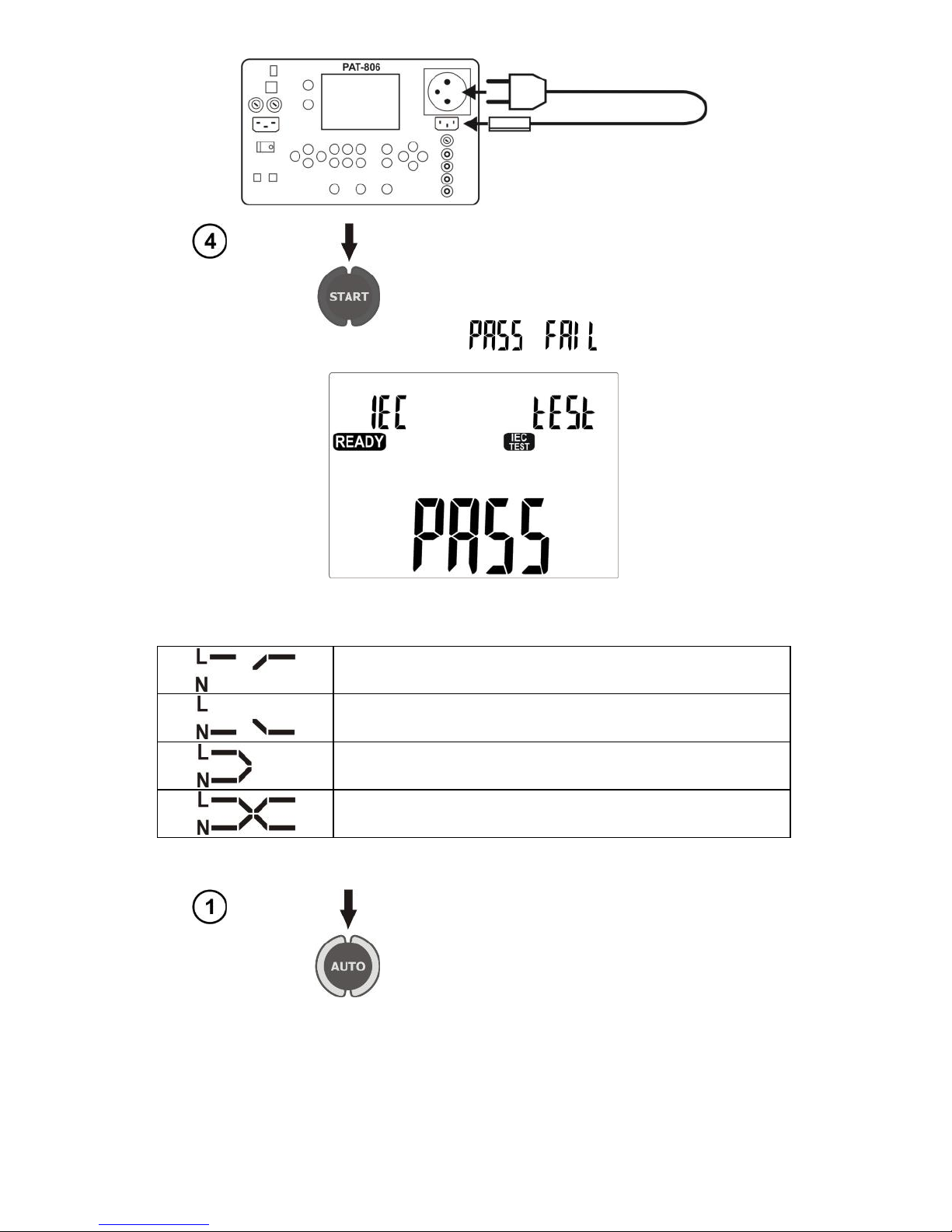
Connect the mains plug into the test socket and the other into
the IEC socket.
Page 49
OPERATING MANUAL PAT-806 version 1.08
47
Press START.
The measurement may be stopped before
the set time runs out by pressing
STOP/ESC.
After measuring is completed, read the re-
sult: or .
Additional information displayed by the meter
Lack of continuity in conductor L.
Lack of continuity in conductor N.
L and N are shorted.
L and N are replaced.
4.15 Automatic tests
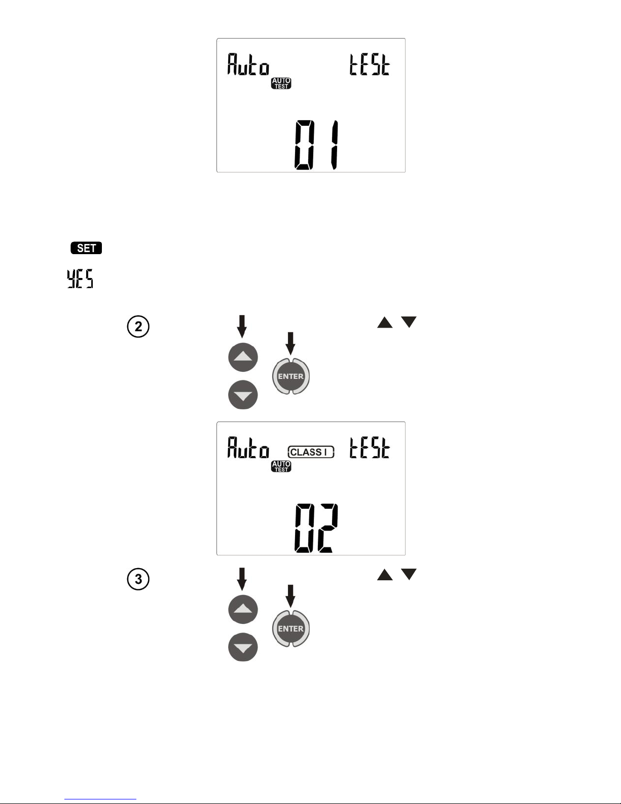
Keep pressing AUTO/IEC, until the screen
with the test choice is displayed (1 ... 20), the
number of test blinks.
Page 50
OPERATING MANUAL PAT-806 version 1.08
48
Notes:
- Only numbers of programmed tests are displayed
- If no test is programmed, after pressing AUTO the meter immediately enters the set-up mode
( is displayed).
- Programmed test is a test where at least for one class, one measurement is performed (set on
).
- Default programmed tests are: 1 ... 4 for all three classes.
Use , to set the
number of chosen test and
confirm by pressing ENTER.
Use , to select the
device class and confirm by
pressing ENTER.
Page 51
OPERATING MANUAL PAT-806 version 1.08
49
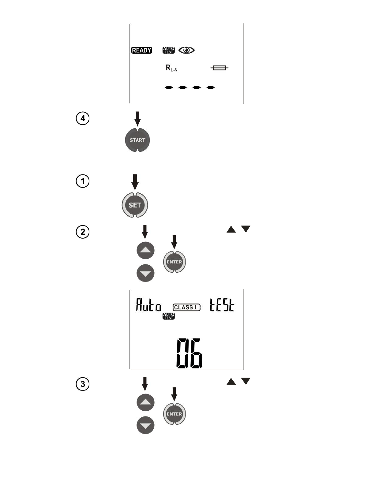
Press START to start the measurement.
To program an inactive test or change the parameters, after entering the AUTO mode ...
...press SET button.
Use , to set the
number of chosen test and
confirm by pressing ENTER.
Use , to select the
device class and confirm by
pressing ENTER.
Page 52
OPERATING MANUAL PAT-806 version 1.08
50
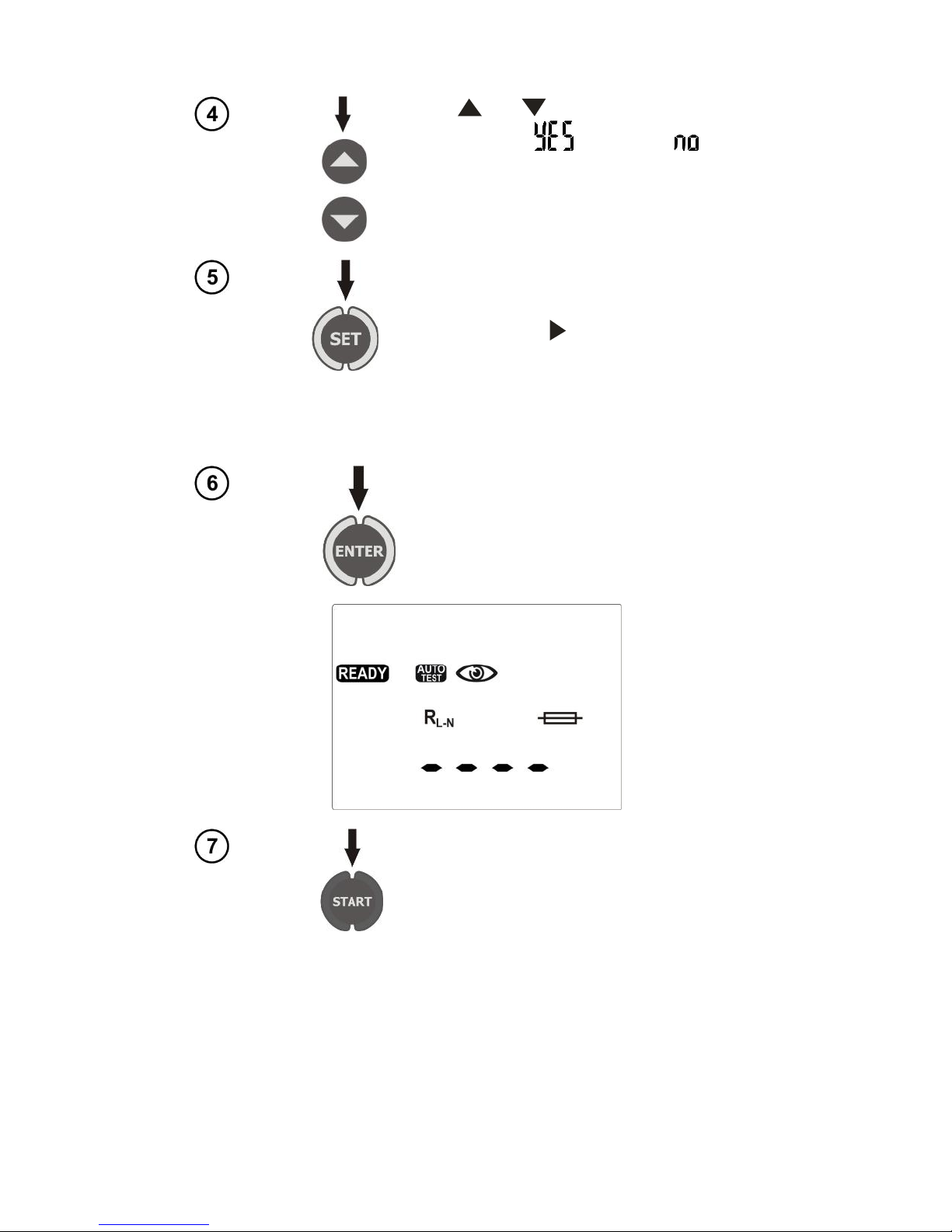
Now you can choose performing of individual measurements for a given test and class.
Use and to choose performing the
measurement ( ) or cancel it ( ).
To change the parameters of the active
measurement press SET. Set the next parameters as in section 4.2. Confirm by press-
ing ENTER. Use to activate and set parameters of the next measurement.
In this way, you may program the test by activating measurements in the following sequence: an
initial measurement → R
E
→ R
ISO
(1 - single, 3 - triple for welding machines)
→ I
SUB
→ I
PE
→ I∆ → I
T
→ I
L
(for welding machines) → Ur (for welding machines) → Up (for welding machines) → S.
After approving the last change by pressing
ENTER press it two more times and the
meter will enter standby mode displaying
the following screen.
Press START to start the measurement.
Notes:
- Readiness for next measurement is obtained automatically, but the individual measurements should
be initiated by pressing START, as in single measurements.
- The duration of the measurement may be reduced by pressing STOP/ESC. The result remains as at
the time of stopping the measurement and the meter turns into standby mode until the next measurement. Double pressing of STOP/ESC interrupts the cycle of automatic measurement and all the
previous results are lost.
Page 53
OPERATING MANUAL PAT-806 version 1.08
51
- If the result of one of the tests is improper ( ), you may record it (finish the autotest by pressing
ENTER and consider the tested device as faulty) or press START to repeat this test (e.g. when improper result was caused by an error in connections).
- For R
ISO
measurement, there are three options: - no R
ISO
measurement, R
ISO
1 - R
ISO
standard
measurement, R
ISO
3 - R
ISO
triple measurement - only for welding machines.
5 Memory of measurement result data
PAT-806 meter has memory divided into 10 banks of 99 cells. Each measurement result can be
stored in a memory cell marked with a selected number and in a selected memory bank. Thanks to
this, the user of the meter can, at his/her option, assign memory cell numbers to individual measurement points and the memory bank numbers to individual facilities. The user can also perform measurements in any sequence and repeat them without losing other data.
Memory of measurement result data is not deleted when the meter is switched off. Thanks to
this, the data can be later read or sent to a computer. The number of a current memory cell or
memory bank is not changed either.
Notes:
- In a single cell you may store a set of results and other data (time, barcode, Pass/Fail, limit, etc) for
AUTO and IEC test or the result of a single measurement (+ time, code, Pass / Fail).
- It is recommended to delete the memory after reading the data or before performing a new series of
measurements that may be stored into the same memory cells as the previous ones.
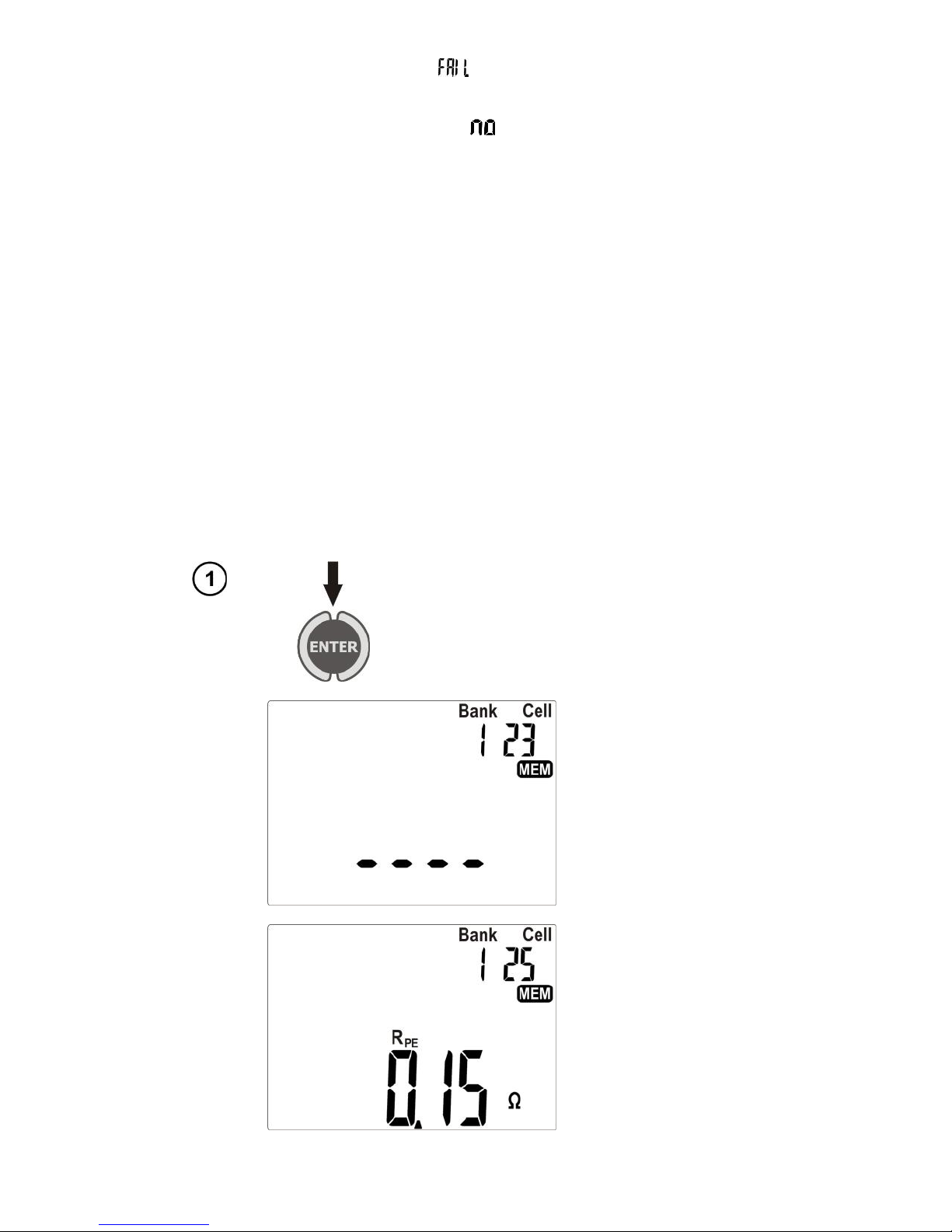
5.1 Storing the measurement results in the memory
After completing measurement
press ENTER.
Free cell.
Cell is filled with the
result of a single
measurement.
Page 54
OPERATING MANUAL PAT-806 version 1.08
52
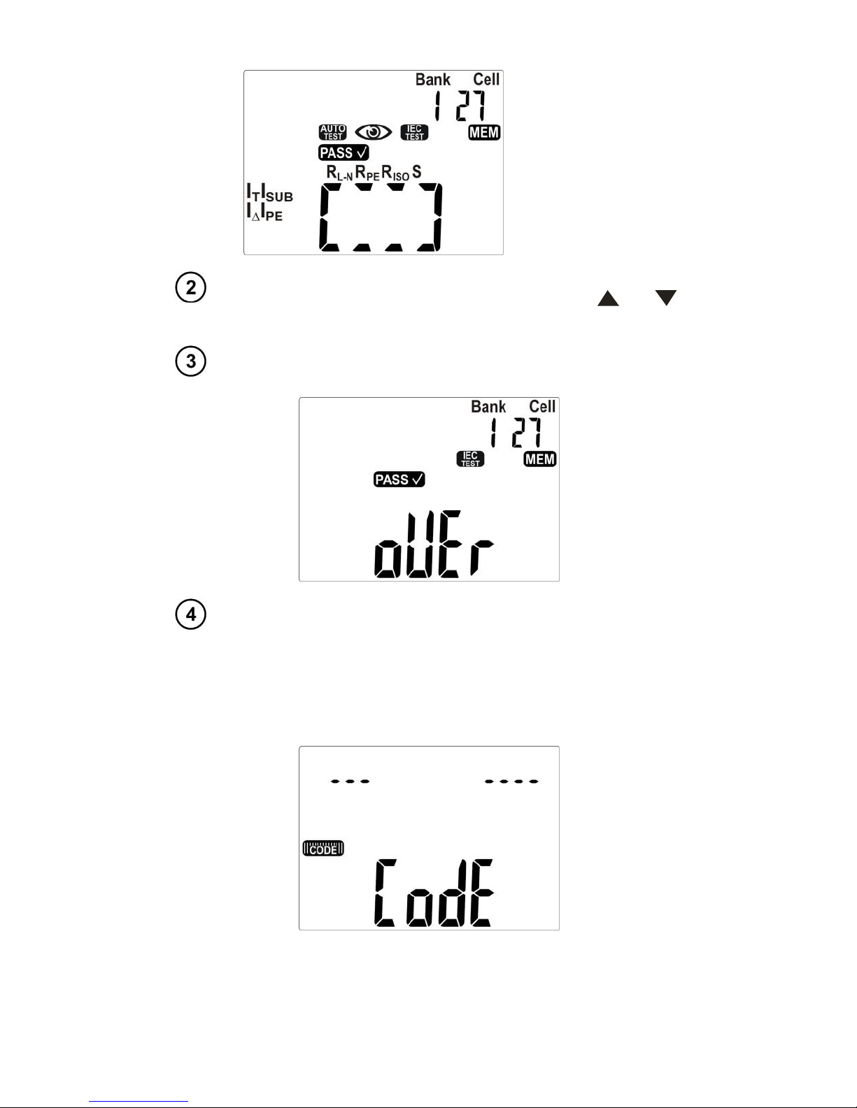
Cell is filled with the
result of AUTO test.
Switch between the number of a bank or number of a cell by pressing SET (chosen digit blinks), chose the number using and .
Enter into the memory by pressing ENTER.
If you try to store data in an occupied memory cell, the following
warning message will appear:
Press ENTER, to overwrite the result or STOP/ESC, to cancel saving.
Notes:
- If the meter is set to work with the barcode reader, before exiting to the screen with the measurement, the following screen will be displayed:
Read the bar-code of the tested device, then the meter will record the result and the code in selected
memory cell, and it will proceed to the measurement screen. In order to skip reading the barcode
press ENTER.
Page 55
OPERATING MANUAL PAT-806 version 1.08
53
5.2 Viewing memory data
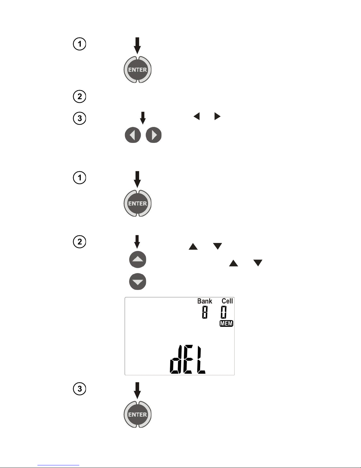
In the mode of displaying the mains
voltage press ENTER.
To select a number of the data bank and cell, proceed as described in 5.1.
Using and you may scroll through
the components of the result and other
data such as date/time of measurement
and bar code.
5.3 Deleting memory data
In the mode of displaying the network
voltage press ENTER.
5.3.1 Deleting bank data
Use and set the number of a
cell on 0. Press SET to select the num-
ber of a bank. Use and set the
bank number to be deleted.
Press ENTER. A message will be displayed asking you to confirm your
choice and informing about the loss of
data contained in the bank.
Page 56
OPERATING MANUAL PAT-806 version 1.08
54
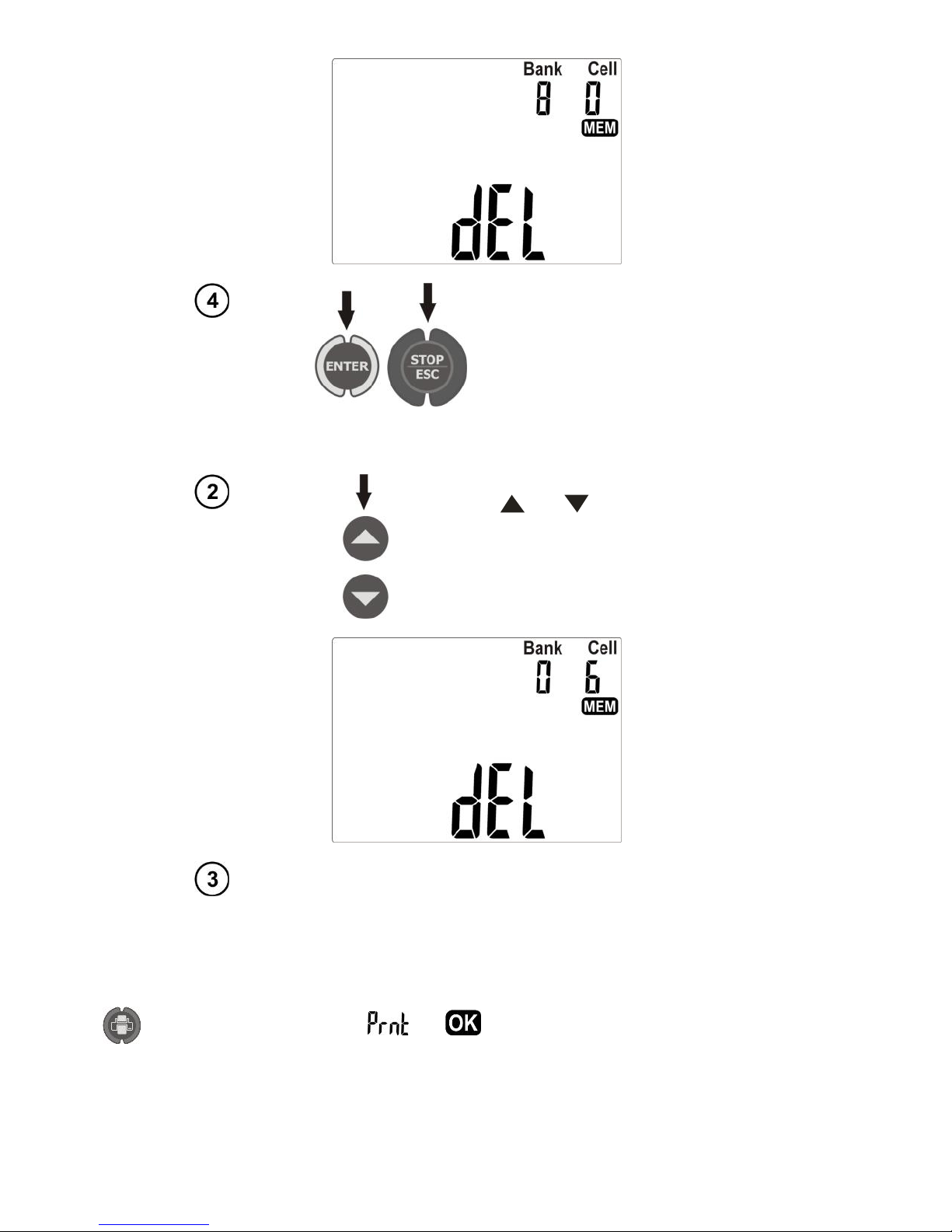
Press ENTER, to start deleting or
STOP/ESC, to cancel.
5.3.2 Deleting the whole memory
Use and set the number of
bank at 0.
Proceed similarly as when deleting data bank.
6 Report printing
To print a measurement report set the operation with printer in general settings (par. 3.2.6). The
printer must be connected to any of the USB socket of "Host" type. To start printing, press button
. Te following will be displayed and . Printing may be activated:
after completing a single measurement, when the result is presented,
After completing the measurement in AUTO mode, when the result is presented,
while browsing the memory, if the selected cell contains data.
Page 57

OPERATING MANUAL PAT-806 version 1.08
55
If the meter is set to work with the barcode reader, the meter will ask you to read the code (see
par. 5.1). This does not apply printing from a memory cell which had the barcode already saved.
Supported types of printers: Brother QL-720NW, Brother PT-9700PC.
7 Data transmission
7.1 Computer connection accessories
In order to operate the meter with a PC, an USB cable is required and appropriate software. The
kit includes "Sonel Reader" software used for reading data. Increased ability to read data and create
reports are provided by "Sonel PAT" software, which can be purchased from the manufacturer or authorized distributor.
The software may be used for many devices manufactured by SONEL S.A. which are equipped
with the USB interface.
Detailed information regarding software is available from the manufacturer or an authorised distributor.
7.2 Data transmission with USB port
1. Connect the cable to the USB port of the computer and the USB socket of the meter.
2. In general settings, select data transmission (section 3.2.3).
3. Start the programme.
8 Cleaning and maintenance
NOTE!
Apply solely the maintenance methods specified by the manufacturer in this manual.
The casing of the meter may be cleaned with a soft, damp cloth using all-purpose detergents. Do
not use any solvents or cleaning agents which might scratch the casing (powders, pastes, etc.).
The electronic system of the meter does not require maintenance.
9 Storage
In the case of storage of the device, the following recommendations must be observed:
Disconnect all the test leads from the meter.
Clean the meter and all its accessories thoroughly.
10 Dismantling and Disposal
Used electrical and electronic equipment should be collected selectively, i.e. it must not be
placed with another kinds of waste.
Used electronic equipment should be sent to a collection point in accordance with the Used Electrical and Electronic Equipment Act.
Before the equipment is sent to a collection point, do not dismantle any elements.
Observe the local regulations concerning disposal of packages.
Page 58

OPERATING MANUAL PAT-806 version 1.08
56
11 Annexes
11.1 Technical specifications
Abbreviation "m.v." used in the specification of measurement uncertainty means a standard
measured value.
Ranges and uncertainties are additionally provided according to DIN VDE 404-1.
Measurement of network voltage
Display range
Resolution
Measurement uncertainty
(basic)
187.0 V…265.0 V
0.1 V
(2 % m.v. + 2 digits)
measurement of the mains voltage between L and N of power supply to the meter
Measurement of network frequency
Display range
Resolution
Measurement uncertainty
(basic)
45.0 Hz…55.0 Hz
0.1 Hz
(2 % m.v. + 2 digits)
measurement of the mains voltage frequency of power supply to the meter
Measurement of PE network (mains) voltage
Display range
Resolution
Measurement uncertainty
(basic) *
0.0 V ... 59.9 V
0.1 V
(2 % m.v. + 2 digits)
measurement of the mains voltage between PE and N of power supply to the meter
* for U < 5 V accuracy ic not specified
Resistance measurement for L - N circuit
Display range
Resolution
Measurement uncertainty
(basic)
0 Ω…999 Ω
1 Ω
(5 % m.v. + 5 digits)
1.00 kΩ ... 4.99 kΩ
0.01 kΩ
test voltage: 4 V ... 8 V AC
short-circuit current: max. 5 mA
Checking the fuse
test voltage: 4 V ... 8 V AC
test current: max. 5 mA
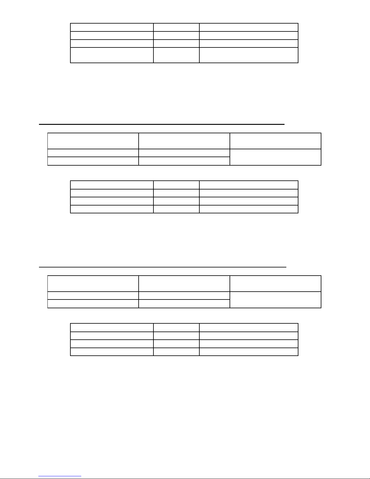
Measurement resistance of protective conductor I=200 mA (only Protection Class I)
Display range
Resolution
Measurement uncertainty
(basic)
0.00 Ω ... 0.99 Ω
0.01 Ω
(4 % m.v. + 2 digits)
1.00 Ω ... 19.99 Ω
(4 % m.v. + 3 digits)
Page 59
OPERATING MANUAL PAT-806 version 1.08
57
Influencing factor
Designation
Additional uncertainty
Position
E1
0 %
Supply voltage
E2
0 %
Temperature
E3
0.1 %/° C for R ≥ 0.5 Ω
0 %/ºC for R < 0.5 Ω
unloaded output voltage: 4 V ... 12 V AC
Test current: ≥ 200 mA for R = 0.2 Ω ... 1.99 Ω
adjustable upper limit in the range of: 10 mΩ …1.99 Ω with resolution 0.01 Ω
adjustable measuring time: 1 s…60 s with a resolution of 1 s, and "Cont" mode (continu-
ous measurement) at point 0
Measurement resistance of protective conductor I=10 A (only Protection Class I)
Display range
Resolution
Measurement uncertainty
(basic)
0 mΩ...999 mΩ
1 mΩ
(3 % m.v. + 4 digits)
(3 % m.v. + 40 digits)*
1.00 Ω ... 1.99 Ω
0.01 Ω
* for two-wire measurement
Influencing factor
Designation
Additional uncertainty
Position
E1
0 %
Supply voltage
E2
0 %
Temperature
E3
0.1 %/ºC
unloaded output voltage: <12 V AC
Test current: ≥ 10 A for R ≤ 0.5 Ω
adjustable upper limit in the range of: 10 mΩ …1.99 Ω with resolution 0.01 Ω
adjustable measuring time in the range of: 1 s…60 s with resolution of 1 s
Measurement resistance of protective conductor I=25 A (only Protection Class I)
Display range
Resolution
Measurement uncertainty
(basic)
0 mΩ...999 mΩ
1 mΩ
(3 % m.v. + 4 digits)
(3 % m.v. + 40 digits)*
1.00 Ω ... 1.99 Ω
0.01 Ω
* for two-wire measurement
Influencing factor
Designation
Additional uncertainty
Position
E1
0 %
Supply voltage
E2
0 %
Temperature
E3
0.1 %/ºC
unloaded output voltage: <12 V AC
test current: ≥ 25 A for R ≤ 0.2 Ω
adjustable upper limit in the range of: 10 mΩ …1.99 Ω with resolution 0.01 Ω
adjustable measuring time in the range of: 1 s…60 s with resolution of 1 s
Page 60
OPERATING MANUAL PAT-806 version 1.08
58
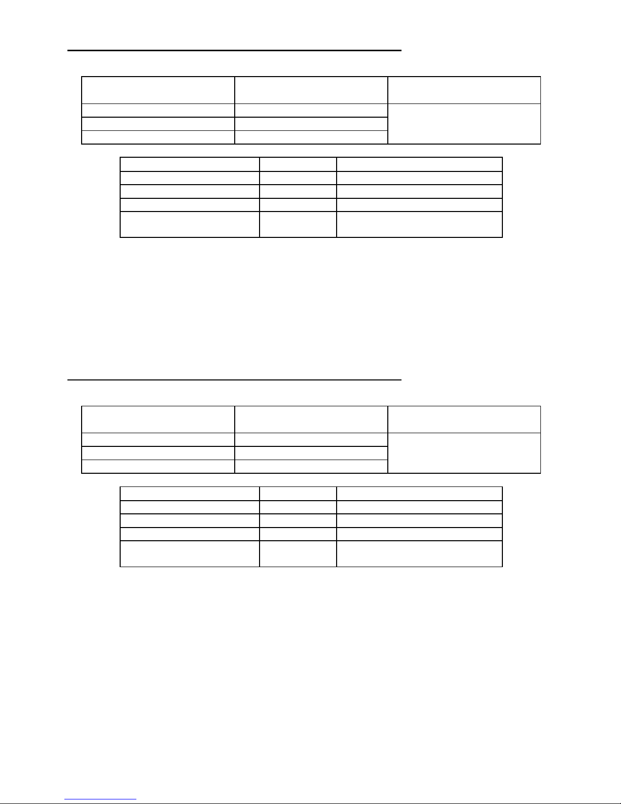
Measurement of insulation resistance using test voltage of 100 V
Test range according to IEC 61557-2 for UN = 100 V: 100 kΩ…99.9 MΩ
Display range
Resolution
Measurement uncertainty
(basic)
0 kΩ...1999 kΩ
1 kΩ
(5 % m.v. + 8 digits)
2.00 MΩ ... 19.99 MΩ
0.01 MΩ
20.0 MΩ ... 99.9 MΩ
0.1 MΩ
Influencing factor
Designation
Additional uncertainty
Position
E1
0 %
Supply voltage
E2
0 %
Temperature
E3
0.1 %/ºC
Capacity
E7
0 % for R ≤ 20 MΩ
unspecified for R> 20 MΩ
Accuracy of generated voltage (Robc [] 1000*UN [V]): -0 % +30 % from the set value
nominal current: min 1 mA ... 1.4 mA
adjustable lower limit within the range of 0.1 MΩ ….9.9 MΩ with resolution of 0.1 MΩ
adjustable measuring time: "Cont" mode (continuous measurement) 4 s…3 min with a resolu-
tion of 1 s
detection of a dangerous voltage before commencing a measurement
discharging the object tested
Note: For R <50 kΩ, the uncertainty is not specified.
Measurement of insulation resistance using test voltage of 250 V
Test range according to IEC 61557-2 for UN = 250 V: 250 kΩ…199.9 MΩ
Display range
Resolution
Measurement uncertainty
(basic)
0 kΩ...1999 kΩ
1 kΩ
(5 % m.v. + 8 digits)
2.00 MΩ ... 19.99 MΩ
0.01 MΩ
20.0 MΩ...199.9 MΩ
0.1 MΩ
Influencing factor
Designation
Additional uncertainty
Position
E1
0 %
Supply voltage
E2
0 %
Temperature
E3
0.1 %/ºC
Capacity
E7
0 % for R ≤ 20 MΩ
unspecified for R> 20 MΩ
Accuracy of generated voltage (Robc [] 1000*UN [V]): -0 % +30 % from the set value
nominal current: min 1 mA ... 1.4 mA
adjustable lower limit within the range of 0.1 MΩ ….9.9 MΩ with resolution of 0.1 MΩ
adjustable measuring time: "Cont" mode (continuous measurement) 4 s…3 min with a resolu-
tion of 1 s
detection of a dangerous voltage before commencing a measurement
discharging the object tested
Note: For R <50 kΩ, the uncertainty is not specified.
Page 61
OPERATING MANUAL PAT-806 version 1.08
59
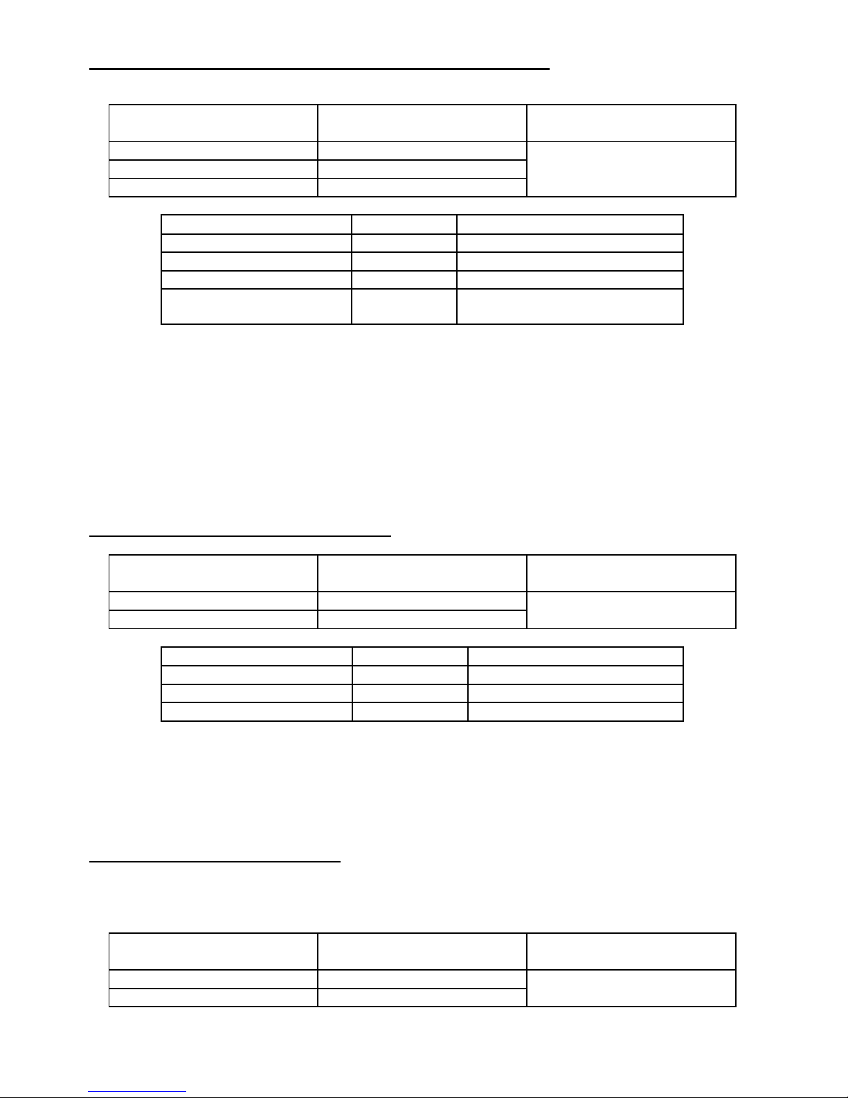
Measurement of insulation resistance using test voltage of 500 V
Test range according to IEC 61557-2 for UN = 500 V: 500 kΩ…599.9 MΩ
Display range
Resolution
Measurement uncertainty
(basic)
0 kΩ...1999 kΩ
1 kΩ
(5 % m.v. + 8 digits)
2.00 MΩ ... 19.99 MΩ
0.01 MΩ
20.0 MΩ...599.9 MΩ
0.1 MΩ
Influencing factor
Designation
Additional uncertainty
Position
E1
0 %
Supply voltage
E2
0 %
Temperature
E3
0.1 %/ºC
Capacity
E7
0 % for R ≤ 20 MΩ
unspecified for R> 20 MΩ
Accuracy of generated voltage (Robc [] 1000*UN [V]): -0 % +30 % from the set value
nominal current: min 1 mA ... 1.4 mA
adjustable lower limit within the range of 0.1 MΩ ….9.9 MΩ with resolution of 0.1 MΩ
adjustable measuring time: "Cont" mode (continuous measurement) 4 s…3 min with a resolu-
tion of 1 s
detection of a dangerous voltage before commencing a measurement
discharging the object tested
Note: For R <50 kΩ, the uncertainty is not specified.
Measurement of substitute leakage current
Display range
Resolution
Measurement uncertainty
(basic)
0.00 mA ... 3.99 mA
0.01 mA
(5 % m.v. + 2 digits)
4.0 mA ... 19.9 mA
0.1 mA
Influencing factor
Designation
Additional uncertainty
Position
E1
0 %
Supply voltage
E2
0 %
Temperature
E3
0.075 %/ºC
opening voltage: 25 V ... 50 V
internal resistance of the testing device 2 kΩ ± 20 %
adjustable upper limit in the range of: 0.01 mA ... 9.9 mA 0.01 mA with resolution of 0.01 mA
/ 0.1 mA
adjustable measuring time in the range of: Cont , 4 s…60 s with resolution of 1 s
Measurement of PE leakage current
Note: In the half-time of the measurement, the meter automatically changes the polarity of the test
socket and as a final result it displays the value of higher leakage current.
Display range
Resolution
Measurement uncertainty
(basic)
0.00 mA ... 3.99 mA
0.01 mA
(5 % m.v. + 2 digits)
4.0 mA ... 19.9 mA
0.1 mA
Page 62
OPERATING MANUAL PAT-806 version 1.08
60
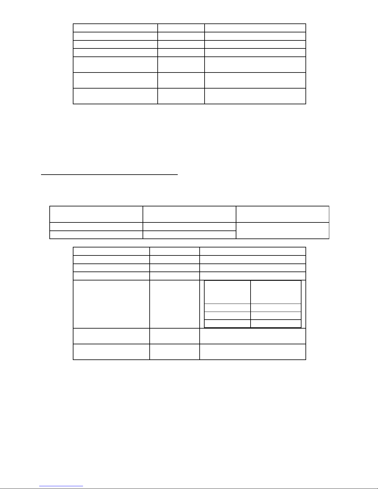
Influencing factor
Designation
Additional uncertainty
Position
E1
0 %
Supply voltage
E2
0 %
Temperature
E3
0.1 %/ºC
Power consumption of
the tested unit
E4
0 %
Low frequency magnetic
field
E5
0.02 mA I <4 mA
0 for I ≥ 4 mA
The shape of the network
voltage (CF)
E8
0 %
measurements are made using mains voltage
bandwidth of current measurement 40 Hz ... 100 kHz
uncertainty related to the measurement within the bandwidth up to 100 kHz should not ex-
ceed ± 3 dB for 100 kHz
adjustable upper limit in the range of: 0.01 mA ... 9.9 mA with resolution of 0.01 mA / 0.1 mA
adjustable measuring time in the range of: Cont , 4 s…60 s with resolution of 1 s
Measurement of differential leakage current
Note: In the half-time of the measurement, the meter automatically changes the polarity of the test
socket and as a final result it displays the value of higher leakage current.
Display range
Resolution
Measurement uncertainty
(basic)
0.00 mA ... 3.99 mA
0.01 mA
(5 % m.v. + 2 digits)
4.0 mA ... 19.9 mA
0.1 mA
bandwidth of current measurement 20 Hz ... 100 kHz
uncertainty related to the measurement within the bandwidth up to 100 kHz should not ex-
ceed ± 3 dB for 100 kHz
adjustable upper limit in the range of: 0.01 mA ... 9.9 mA with resolution of 0.01 mA / 0.1 mA
adjustable measuring time in the range of: Cont , 4 s…60 s with resolution of 1 s
Influencing factor
Designation
Additional uncertainty
Position
E1
0 %
Supply voltage
E2
0 %
Temperature
E3
0.1 %/ºC
Power consumption of
the tested unit
E4
Current
common
Additional un-
certainty
0 A...4 A
0
4 A...8 A
±0.03 mA
8 A...16 A
±0,08 mA
Low frequency magnetic field
E5
2 digits I <4 mA
0 digit for I ≥ 4 mA
The shape of the network voltage (CF)
E8
0 %
Page 63
OPERATING MANUAL PAT-806 version 1.08
61
Measurement of touch leakage current
Display range
Resolution
Measurement uncertainty
(basic)
0.000 mA...4.999 mA
0.001 mA
(5 % m.v. + 3 digits)
Influencing factor
Designation
Additional uncertainty
Position
E1
0 %
Supply voltage
E2
0 %
Temperature
E3
0,25 μA/ºC
The shape of the network
voltage (CF)
E8
0 %
the bandwidth of test current results from the measuring system with adjusted touch current
which simulates human perception and reaction, in accordance with EN 60990: 2002
adjustable upper limit in the range of: 0.01 mA ... 1.99 mA with resolution 0.01 mA
adjustable measuring time in the range of: Cont , 4 s…60 s with resolution of 1 s
Rated voltage measurement on welding equipment without load U0
Measurement of voltage UR (r.m.s.)
Display range
Resolution
Measurement uncertainty
(basic)
5.0 V…170.0 V
0.1 V
(2.5 % m.v. + 5 digits)
adjustable upper limit in the range of: 5,0 V…170,0 V with resolution of 1 V
Measurement of voltage UP (peak)
Display range
Resolution
Measurement uncertainty
(basic)
5.0 V…240.0 V
0.1 V
(2.5 % m.v. + 5 digits)
adjustable upper limit in the range of: 5.0 V…240.0 V with resolution of 1 V
Leakage current measurement on welding circuit IL
Display range
Resolution
Measurement uncertainty
(basic)
0.00 mA…14.99 mA
0.01 mA
(5 % m.v. + 2 digits)
Influencing factor
Designation
Additional uncertainty
Position
E1
0 %
Supply voltage
E2
0 %
Temperature
E3
0.25 μA/ºC
The shape of the network
voltage (CF)
E8
0 %
current measurement range results from the applied measurement system, which is in ac-
cordance with EN 60974-4
adjustable upper limit in the range of: 0.10 mA…14.90 mA with resolution of 0.1 mA
adjustable measuring time in the range of: 6 s…60 s with resolution of 1 s
Page 64

OPERATING MANUAL PAT-806 version 1.08
62
Power measurement S
Display range
Resolution
Measurement uncertainty
(basic)
0 VA...999 VA
1 VA
(5 % m.v. + 3 digits)
1 kVA …3.99 kVA
0.01 kVA
adjustable measuring time in the range of: Cont , 1 s…60 s with resolution of 1 s
Current consumption measurement
Display range
Resolution
Measurement uncertainty
(basic)
0.00 A ... 15.99 A
0.01 A
(2 % m.v. + 3 digits)
adjustable measuring time in the range of: Cont , 1 s…60 s with resolution of 1 s
Measurement of voltage at the test socket
Display range
Resolution
Measurement uncertainty
(basic)
187.0 V ... 265.0 V
0.1 V
(2 % m.v. + 2 digits)
Other technical specification
a) type of insulation ................................ ...................... double, EN 61010-1 and IEC 61557 compliant
NOTE!
During the measurement of S, I∆, IPE and IT PE of the power supply socket is connected to PE of the test socket.
b) measurement category ........................................................................ II 300 V acc. to EN 61010-1
c) protection class of enclosure acc. to EN 60529 ....................................................................... IP40
d) power supply for the meter ................................................................ .............. 187 V…265 V, 50 Hz
e) load current .......................................................................................................... max 16 A (230 V)
f) dimensions ........................................................................................ 330 mm x 235 mm x 120 mm
g) meter weight ............................................................................................................. approx. 5,0 kg
h) storage temperature................................................................................................ –20 C...+70 C
i) operating temperature ................................................................................................. 0 C...+40 C
j) humidity ....................................................................................................................... 20 %…80 %
k) nominal temperature ............................................................................................... +20 C...+25 C
l) reference humidity ....................................................................................................... 40 %…60 %
m) altitude (above sea level) .................................................................................................. < 2000 m
n) display ...................................................................................................................... LCD, segment
o) memory of measurement results ....................................................................................... 990 cells
p) data transmission................................................................................................................ USB 2.0
q) quality standard .......................... development, design and manufacturing are ISO 9001 compliant
r) the product meets the EMC requirements acc. to ......... EN 61326-1:2009 and EN 61326-2-2:2006
Page 65

OPERATING MANUAL PAT-806 version 1.08
63
Note:
During the measurement of PE continuity with PE 10/25 current the meter may produce interference with values exceeding allowable limits defined in EN 61326-1 and
cause interference in other devices.
Note:
F500mA/250V fuse protects the following measurements: R
PE
200mA, IT and IL.
11.2 Standard equipment
Standard set of equipment supplied by the manufacturer includes:
power lead 1pc – WAPRZZAS1
test lead banana/banana, black 1.2m 1pc – WAPRZ1X2BLBB2X5
1.2 m double-wire lead (10/25A) U2/I2 1pc – WAPRZ1X2DZBB2
black crocodile clip 1kV 1pc – WAKROBL30K03
Kelvin crocodile clip 1pc (PAT-805) – WAKROKELK06
1kV probe - black 1pc – WASONBLOGB3
power probe Sonel 1pc (PAT-805) – WASONSPGB1
USB cable – WAPRZUSB
fuse 0314 015.VXP 15A 250VAC 6.3x32mm Littlefuse 2 pcs – WAPOZB15PAT
cover – WAFUTL5
operating manual
11.3 Optional accessories
Additionally, the following items that are not included in the scope of standard equipment can be
purchased from the manufacturer or the distributors:
barcode stickers
PASS stickers (roll - 50 pieces of stickers)
FAIL stickers (roll - 50 pieces of stickers)
barcode stickers (roll - 100 stickers)
1.2 m double-wire lead (10/25A) U1/I1 1pc – WAPRZ1X2DZBB1
black crocodile clip 1kV 1pc – WAKROBL20K01
1kV probe -black 1pc – WASONBLOGB3
test lead banana/banana, black 1.2m 1pc– WAPRZ1X2BLBB
cable - adapter Shuko / IEC (for testing extensions) – WAADAPATIEC1
three phase socket adapter 16A* – WAADAPAT16P
three phase socket adapter 16A, switchable** – WAADAPAT16PR
three phase socket adapter 32A* – WAADAPAT32P
three phase socket adapter 32A, switchable**– WAADAPAT32PR
adapter for industrial sockets 16A*** – WAADAPAT16F1
adapter for industrial sockets 32A*** – WAADAPAT32F1
adapter IEC 60320 C6 Plug to IEC 60320 C13 Connector Block – WAADAPATIEC2
USB barcode reader – WAADACK1
USB printer for reports / codes, portable – WAADAD1
Sonel PAT software – WAPROSONPAT1
* - These adapters have permanently shorted lines of three-phase socket: L1, L2, L3 and they are
connected to L line of one-phase socket.
Page 66

OPERATING MANUAL PAT-806 version 1.08
64
** - These adapters have a rotary switch providing the following connections:
1 - L of test socket connected to L1
2 - L of test socket connected to L2
3 - L of test socket connected to L3
4 - L of test socket connected to L1+L2+L3 (shorted)
*** - These adapters are designed for testing security of devices powered from industrial sockets 16 A
and 32 A, providing that the tested device does not consume current higher than 16 A. The adapters
enable users to perform all measurements available in PAT-806 meter on the network measurement
socket.
NOTE!
Adapters for three-phase sockets and for 32 A industrial sockets must not be used for
the following measurements: leakage currents IPE and IΔ, power and current consumption (for detailed information on the use of adapters see PAT Adapters User's Guide).
12 Manufacturer
The manufacturer of the device, which also provides guarantee and post-guarantee service is the
following company:
SONEL S.A.
ul. Wokulskiego 11
58-100 Świdnica
Poland
tel. +48 74 858 38 60
fax +48 74 858 38 09
E-mail: [email protected]
Web page: www.sonel.pl
Attention:
Service repairs must be realised solely by the manufacturer.
Page 67
Page 68

 Loading...