

Page 1
Page 2
Page 3

OPERATING
MANUAL
VOLTAGE TESTER
P-3
SONEL S. A.
ul. Wokulskiego 11
58-100 Świdnica
Version 1.6 May 22, 2012
Page 4

2
TABLE OF CONTENTS
1
SAFETY .............................................. 3
2
MEASUREMENTS ........................... 4
2.1
TESTER OPERATION CONTROL ........ 4
2.2
AC OR DC VOLTAGE TEST .............. 4
2.3
RCD OPERATION TEST .................... 5
2.4
SINGLE-POLE PHASE TESTING .......... 5
2.5
CIRCUIT CONTINUITY TEST ............. 6
2.6
MEASUREMENT OF RESISTANCE ..... 6
2.7
PHASE SEQUENCE TEST ................... 7
2.8
PHASING ......................................... 7
2.8.1
Without transmitter ................. 8
2.8.2
With transmitter ...................... 9
2.9
LIGHTING OF THE MEASURED POINT
..
..................................................... 12
3
BATTERY REPLACEMENT ........ 12
4
CLEANING AND MAINTENANCE
.
........................................................... 13
5
STORAGE ........................................ 13
6
DISMANTLING AND
UTILIZATION
................................ 13
7
TECHNICAL DATA ....................... 14
8
MANUFACTURER ......................... 16
We appreciate your having purchased our voltage tester. The P-3 tester is a modern high-quality,
simple and safe device. However it is recommended
to get acquainted with the present manual in order
to avoid measuring errors and prevent possible
problems related to operation of the meter.
Note:
The producer reserves the right to modify the
appearance, equipment and technical data of
the device.
Page 5

3
1 Safety
The P-3 meter has been devised for the purpose
of voltage and circuit continuity testing, measurement of resistance and indication of the phase spin
direction and phase identification. In order to guarantee proper operation and adequacy of the results
the following recommendations must be observed:
• Before you proceed to operate the meter, ac-
quaint yourself thoroughly with the present
manual and observe the safety regulations and
specifications determined by the producer.
• Any other application than those specified in the
present manual may result in a damage to the
device and constitute a source of danger for the
user.
• The device must be operated solely by appro-
priately qualified personnel with relevant certificates that entitle them to realise measurements
of electric installation. Operation of the meter
realised by unauthorised personnel may result in
damage to the device and constitute a source of
danger for the user.
• The instrument must not be used for mains and
in premises of special conditions, e.g. in a dangerous environment regarding the possibility of
explosion and fire.
• It is unacceptable to operate the following:
⇒ A damaged meter which is completely or
partially out of order,
⇒ A meter with damaged cable insulation,
⇒ A meter stored for an excessive period of
time in disadvantageous conditions (e.g. excessive humidity). If the meter has been
transferred from a cool to a warm environment of a high level of relative humidity, do not realise measurements until the
meter has been warmed up to the ambient temperature (approximately 30 minutes).
• Do not operate a meter with an open or incor-
rectly closed battery compartment or power it
from other sources than those specified in the
present manual.
• Voltage measurements must not last longer
than 30s. Having concluded a 30-second measurement, the following measurement may be
performed not sooner than after 240s.
• Limit value signalling is solely provided as warn-
ing for the operator and not for the purpose of
measurement.
Page 6
4
Note:
The device can be used in rainy conditions,
however at user’s own responsibility.
It is
recommended to use gauntlets.
2 Measurements
2.1 Tester operation control
Before each operation of the tester, its functioning must be checked:
• Test the voltage indicator using a known volt-
age source,
• Short-circuit the measurement probes – there
should be a sound signal, the LED diode Ω
should be lit and there should be the
leg-
end in the display.
Notes:
The voltage indication function is active whether
the batteries are charged or not. Other functions require charged batteries.
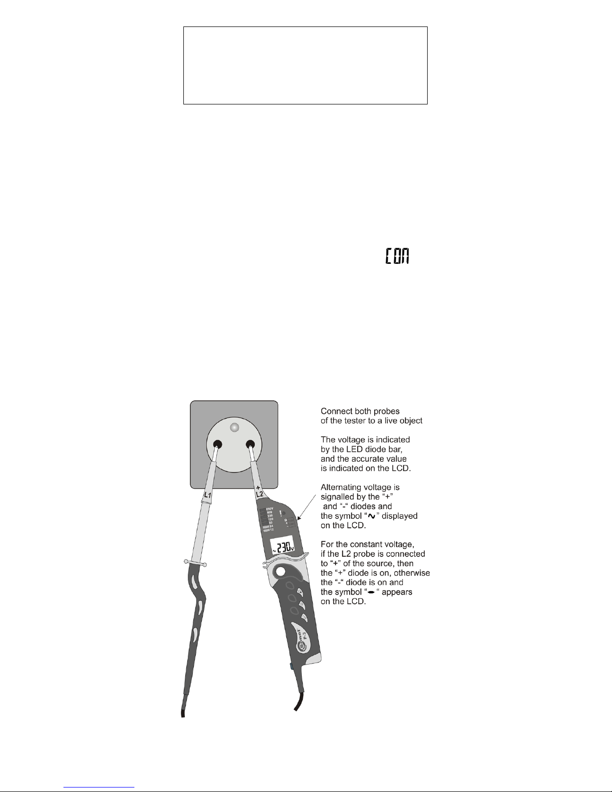
2.2 AC or DC voltage test
Page 7

5
Notes:
In mains protected with an RCD switch, whose
nominal current is 10mA or 30mA, the switch may
be activated during a voltage measurement between
L and PE. In order to avoid that connect the tester
between L and N and after approximately 5s switch
the probe over from N to PE.
2.3 RCD operation test
In order to check the operation of the RCD
switch, whose nominal current is 10mA or 30mA,
perform a voltage test directly between the L phase
and the PE protective conductor.
2.4 Single-pole phase testing
Notes:
During single-pole phase testing for the purpose
of identification of external conductors, under certain
circumstances the functioning of the tester may be
impaired (e.g. if insulated individual protective
means are used or is the working station is insulated).
Note!
Do not touch the measurement probe electrode
L1 during the phase testing.
Page 8
6
Single-pole phase testing may not be sufficient
to determine whether the circuit is live. Perform twopole voltage test.
2.5 Circuit continuity test
Note!
The tested object must not be live.
Connect both probes to the tested object. A
sound signal, diode Ω on, and the
legend indi-
cate continuity of the circuit (R<600kΩ).
Notes:
During the circuit continuity measurement, the
voltage polarization at the L2 probe is negative!
2.6 Measurement of resistance
Note!
The tested object must not be live.
Press the Ω button for a short while and connect
both probes to the tested object. Read the result
from the LCD.
Notes:
During the resistance measurement, the voltage
polarization at the L2 probe is negative!
Page 9
7
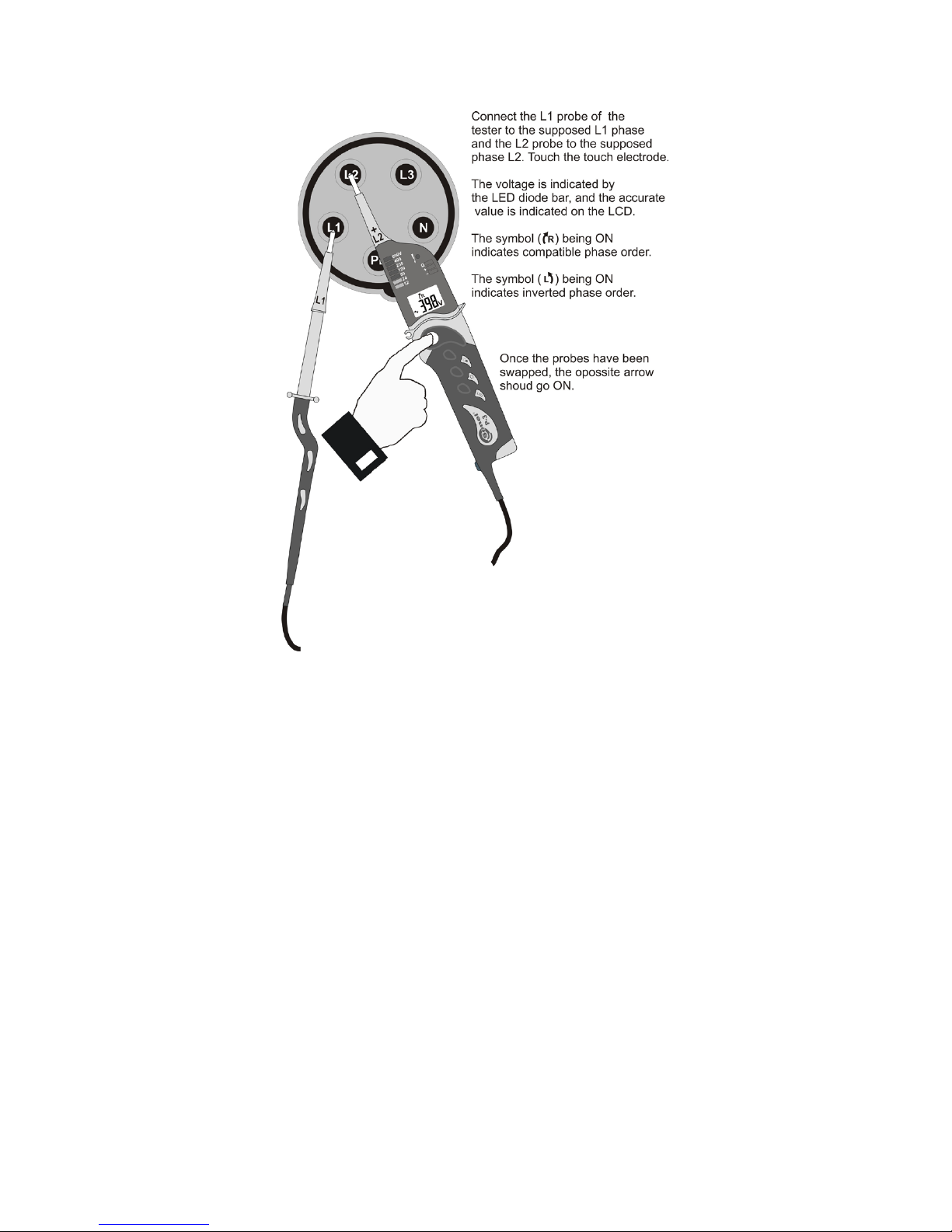
2.7 Phase sequence test
Notes:
The phase sequence may solely be determined
in a three-phase system. Contact of the touch electrode during measurement in a single-phase system
gives a random result.
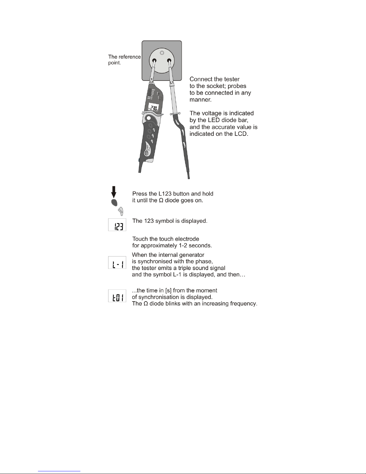
2.8 Phasing
The phasing function facilitates comparison of
voltage phases in two distant point of the installation.
Page 10
8
2.8.1 Without transmitter
Page 11
9
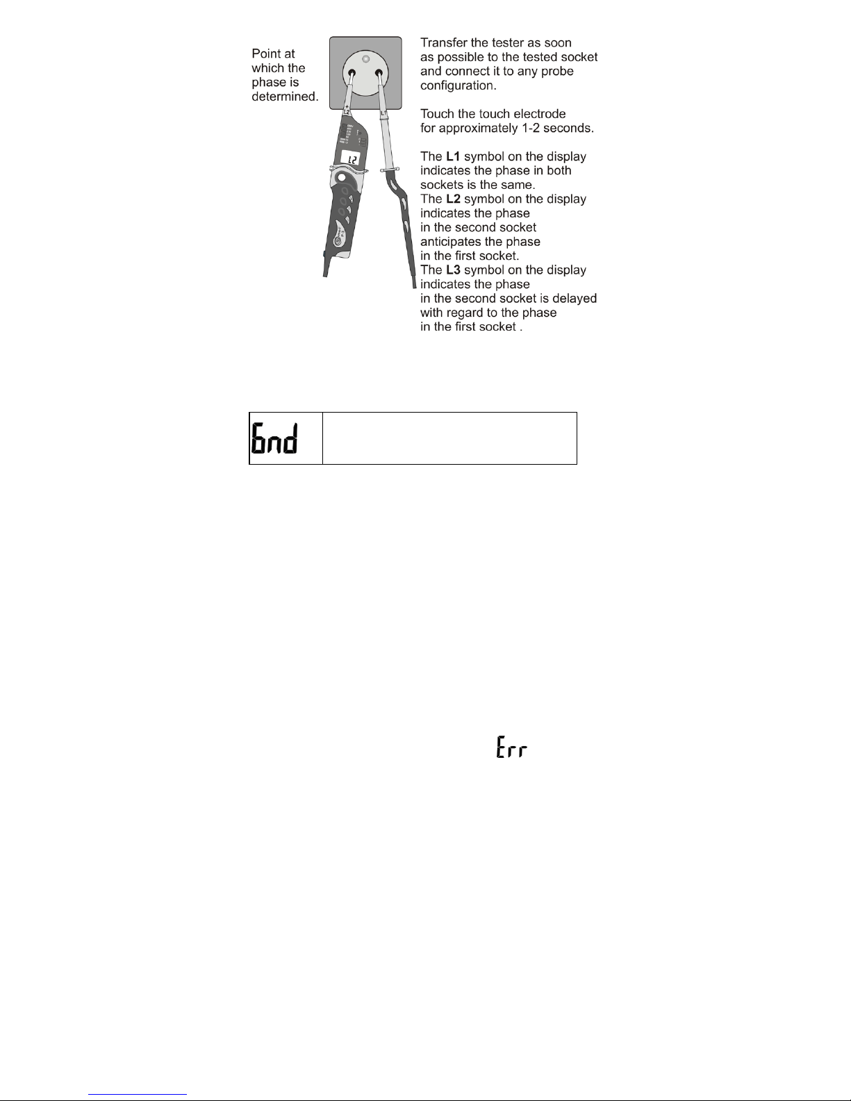
Additional information displayed by the
meter
Touch again the touch electrode. It is
displayed if the previous contact was
too short.
Notes:
- Correct phasing is possible after no more than 15s
from the sound signal. Afterwards horizontal lines
are displayed.
- If before 6s from the moment of synchronisation
the tester is not disconnected from voltage, synchronization commences anew.
- When phase is indicated in another socket and its
symbol is displayed, precise synchronization of the
P-3 receiver commences automatically. Thus phasing between distant sockets is possible, if there are
other sockets in between.
- If the tester is disconnected from voltage before
synchronization has concluded, the
symbol is
displayed.
2.8.2 With transmitter
The transmitter mated with the P-3 tester is a
part of auxiliary equipment.
The new LKN-710P transmitter is not factorydedicated to any P-3 indicator, and therefore before
phasing may commence, it is required to perform
the so called mating (point 2.8.2.1). The transmitter
during a given period may work with solely one P-3
indicator. Repeated mating is required in case another P-3 indicator is to be used.
If the transmitter and indicator mating has not
been performed, go on to point 2.8.2.1 of the manual.
Page 12
10
If both devices were mated before go on to point
2.8.2.2.
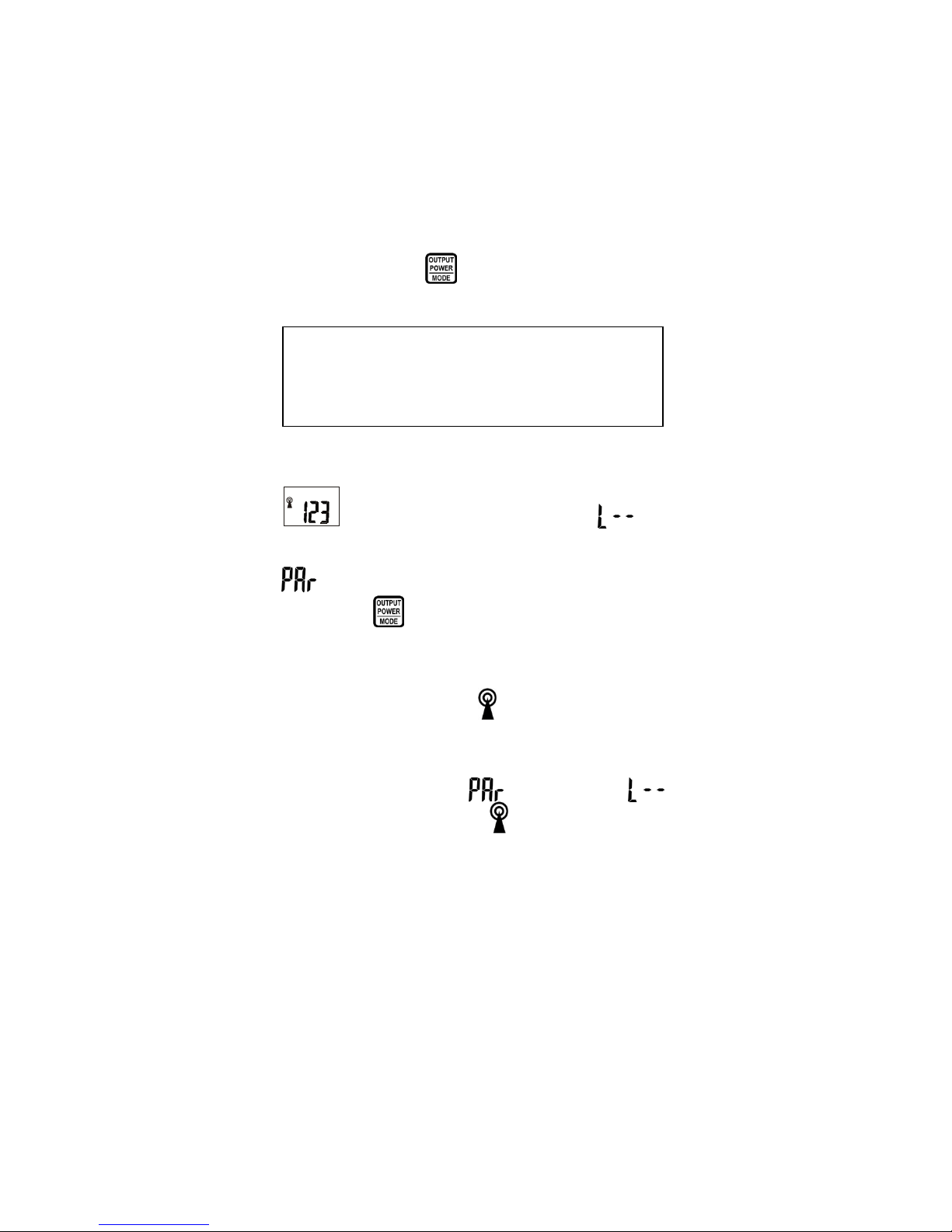
2.8.2.1 Mating
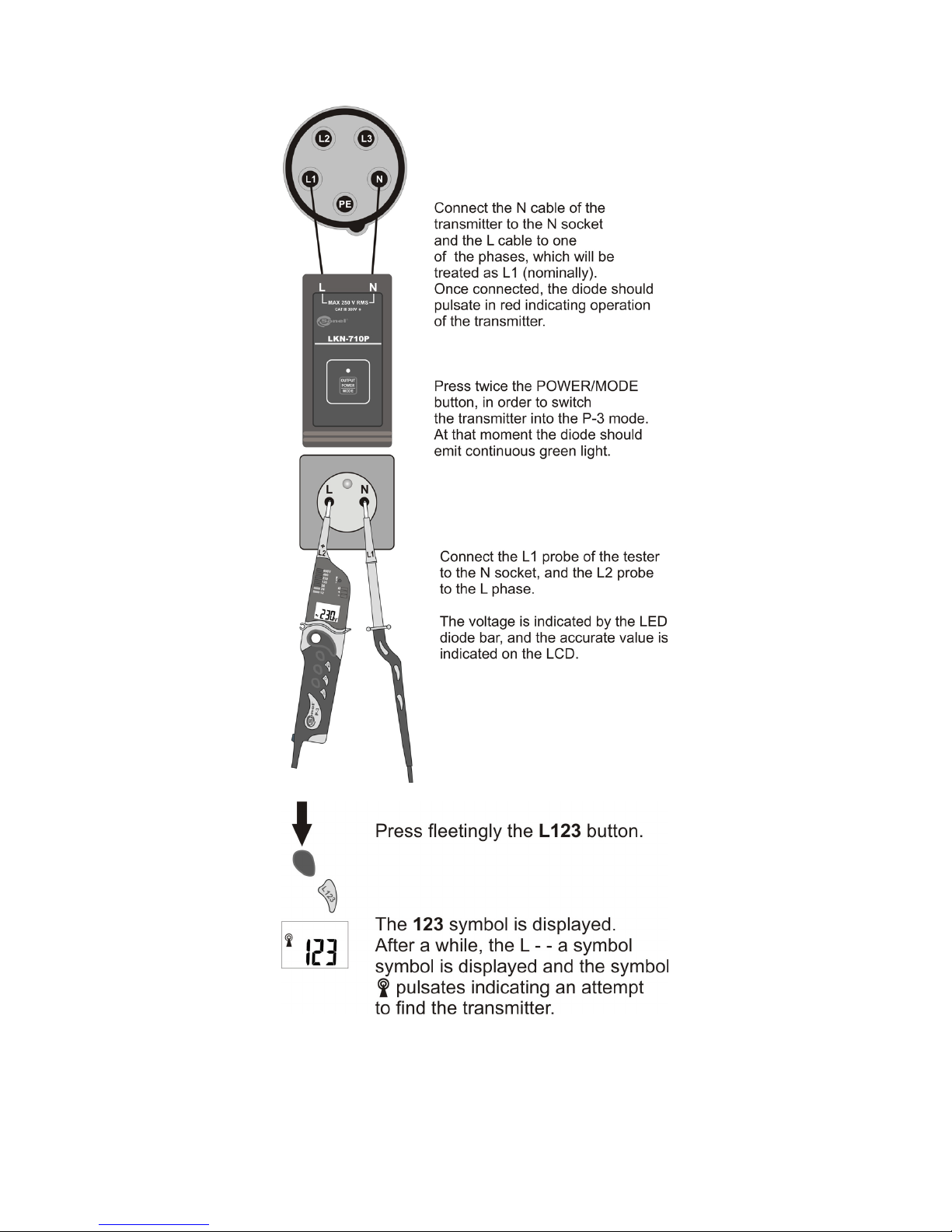
1. Connect the LKN-710P transmitter cables to the
source of alternating voltage 24...230V. After the
connection has been performed, the red diode
should blink signalling its operation in the conductor
tracking mode (along with the LKO-710 received by
SONEL S.A.).
2. Then, press the
button twice, until the diode
turns greed (continuous light).
3. Press fleetingly the L123 button on the P-3 display. The following message should be displayed
and after a short while the symbol .
4. Then hold the L123 button until the message
is displayed
.
5. Keep the
button of the LKN-710P transmitter
until the green diode stops blinking.
6. Now the transmitter is synchronized with the P-3
indicator. The process of synchronization lasts up to
30 seconds. The symbol
may blink during syn-
chronization.
7. Correct mating of the transmitter with the indicator is signalled as follows:
• The message
is replaced by ,
while the symbol
is displayed continu-
ously,
• The green diode of the transmitter blinks
faster than at the moment of mating, signalling transmission of phasing signal.
From that moment on both devices are ready for
work in tandem.
Note :
Green light signal indicated operation of the
transmitter in the P-3 mode.
Page 13
11
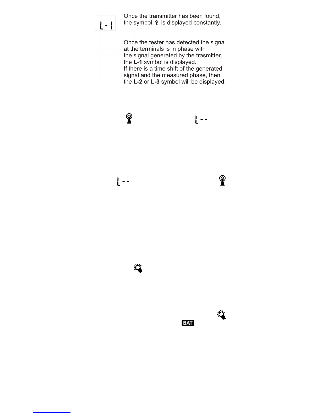
2.8.2.2 Correct work of the P-3 indicator with the
LKN-710P transmitter
Page 14
12
Notes:
If during the phase indication (L-1, L-2 or L-3)
the symbol
starts to blink and the
is displayed, it means there are problems, which may be
related to:
- excessive distance between the transmitter and
the P-3 indicator,
- transmission interference, which is not related to
distance. In such a case, the problem will be solved
automatically in no more than 10-20 seconds.
The
symbol, which appears when the
symbol is displayed continuously means:
- no voltage at the P-3 indicator measurement terminals,
- incorrect connection of the LKN-710P transmitter
or the P-3 indicator.
2.9 Lighting of the measured
point
The P-3 tester may light the measured area under difficult lighting conditions (e.g. in switchgears).
In order to light the measured point, press the fol-
lowing button:
. The LCD is backlit simultane-
ously.
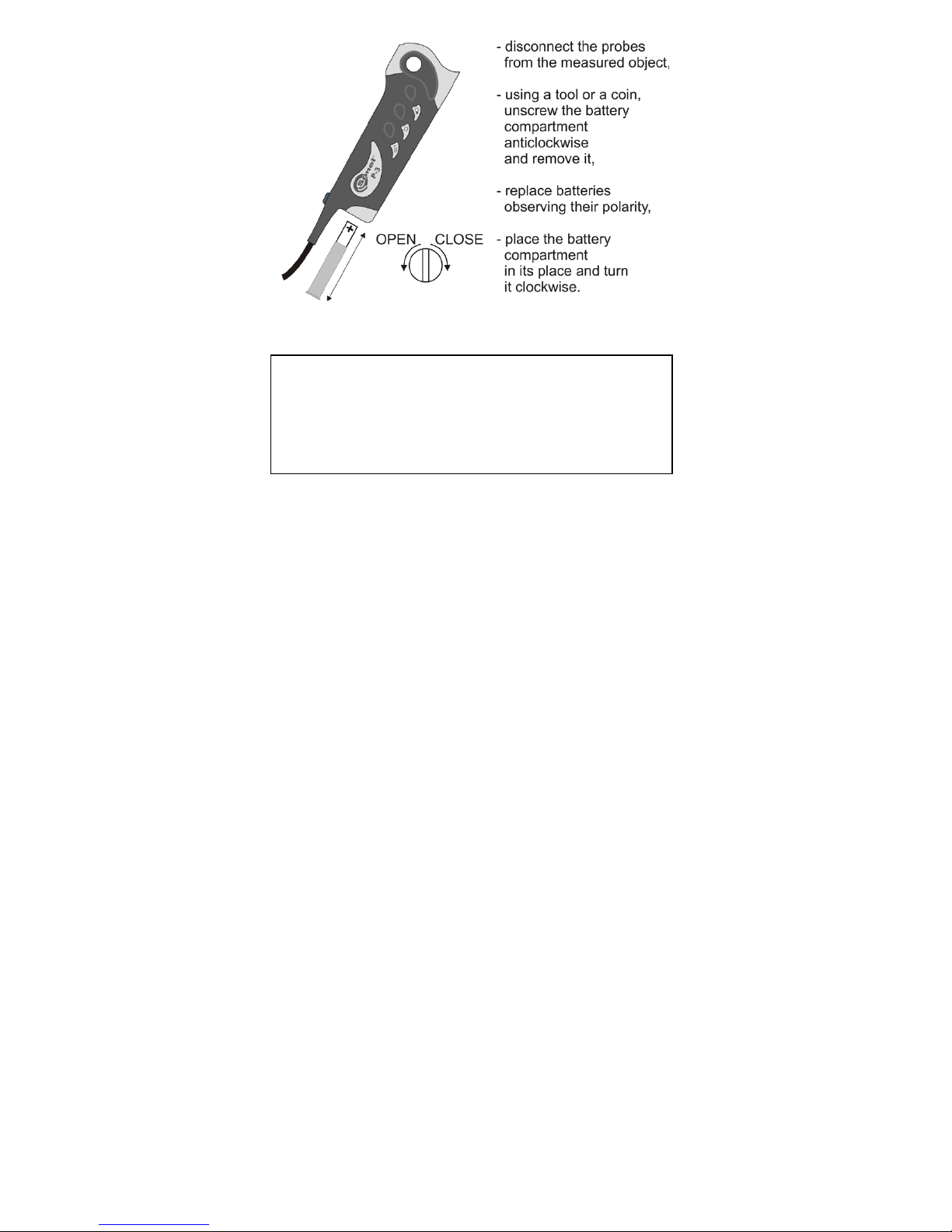
3 Battery replacement
The tester is powered from two 1.5V AAA batteries. A lack of sound signal after the probes have
been short-circuited or dim light after the button
has been pressed, or the symbol
indicate the
need to replace the batteries. In order to do so, perform the following actions:
Page 15
13
4 Cleaning and maintenance
NOTE!
Use solely the maintenance techniques specified by the manufacturer in the present operating manual.
The tester may be cleaned with a soft, damp
cloth using all-purpose detergents. Do not use any
solvents or cleaning agents which might scratch the
casing (powders, pastes, etc.).
The electronic system of the meter does not require maintenance.
5 Storage
In the case of storage of the device, the following recommendations must be observed:
• Place protection on the probes,
• Make sure the tester is dry.
• Should the tester be stored for a prolonged period
of time, the batteries will be removed.
6 Dismantling and utilization
Worn-out electric and electronic equipment
should be gathered selectively, i.e. it must not be
placed with waste of another kind.
Worn-out electronic equipment should be sent
to a collection point in accordance with the law of
worn-out electric and electronic equipment.
Before the equipment is sent to a collection point,
do not dismantle any elements.
Observe the local regulations concerning disposal of packages, worn-out batteries and accumulators.
Page 16
14
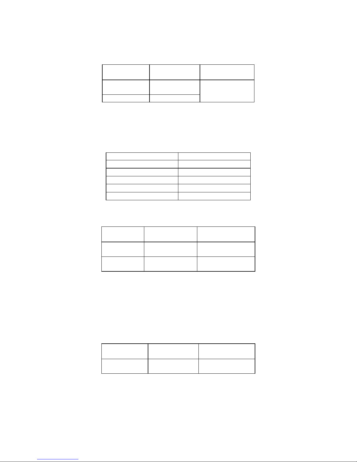
7 Technical data
The abbreviation „i.v.” in the basic uncertainty
definition means the indicated value.
Constant voltage measurement (on the display):
* - from 6,0V for Sr. no. up to 681793
Additionally the voltage is indicated by the diode bar
for the following values: 12, 24, 50, 120, 230, 400,
690V along with the signalling of the voltage polarization (the diode „+” or „-” is lit). The diode indicator
functions also without batteries.
Input resistance
Uin
Rin
12V, 24V, 50V
~ 6kΩ
120V
~ 20kΩ
230V
~ 70kΩ
400V
~ 150kΩ
690V
~ 240kΩ
Alternating voltage measurement within the
range between 20 and 400Hz (on the display):
* - from 6,0V for Sr. no. up to 681793
Additionally the voltage is indicated by the diode bar
for the following values: 12, 24, 50, 120, 230, 400,
690V along with the signalling of alternating voltage
(diodes „+” and „-” are lit simultaneously).
The diode indicator functions also without batteries.
The measurement voltage frequency for the diode
bar: 15…400Hz.
Resistance measurement:
Range Resolution
Basic
uncertainty
0...1999Ω 1Ω
±(3% i.v. + 8 dig-
its)
Other data:
a) Kind of insulation: double, in accordance with
EN 61010-1
b) Measurement category: III 1000V (IV 600V) in
accordance with EN 61010-1
Range Resolution
Basic
uncertainty
+1,5/-2,5*
...49,9V
0,1V
±(2% i.v. + 3
digits)
50...750V
1V
Range Resolution
Basic
uncertainty
1,5*...49,9V 0,1V
±(3% i.v. + 4 dig-
its)
50...750V 1V
±(2% i.v. + 3 dig-
its)
Page 17

15
c) Casing protection grade in accordance with EN
60529: IP65, with an open battery compartment:
IP10
d) Voltage measurement range on the LCD:
6…750V AC/DC
e) Voltage indication for the diode bar: 12V, 24V,
50V, 120V, 230V, 400V, 690V
f) Minimum indicator activation voltage: 6V
g) Accuracy of voltage indications: in accordance
with EN 61243-3
h) Voltage frequency range for the LCD:
20…400Hz
i) Voltage frequency range for the diode bar:
15…400Hz
j) Maximum current: I
S
<0,2A/IS(5s)<3,5mA
k) Maximum period of continuous operation: 30s
l) Minimum interruption of operation after 30 sec-
onds of work: 240s
m) Voltage range for a single-pole phase indicator:
50…690V
n) Frequency range for a single-pole phase indica-
tor: 50…400Hz
o) Continuity tester range: 0…600kΩ (400kΩ for
Sr. no. up to 681793)
p) Accuracy of the continuity tester activation
threshold: ±50%
q) Continuity tester measurement current: 7μA
r) Voltage range for two-pole phase sequence in-
dicator: 100…690V
s) Frequency range for two-pole phase sequence
indicator: 50…60Hz
t) Time to automatic turn-off (Auto-OFF):
approximately 7s
during phasing approximately 30s
u) Display: LCD 3 1/2 digits
v) Tester power supply: 2x1,5V AAA/LR03
(alkaline batteries are recommended)
w) Dimensions: approximately 240x60x30 mm
x) Mass of the tester with batteries:
approximately 0,2kg
y) Working temperature: -10..+55°C
z) Storage temperature: -30..+70°C
aa) Quality standard: design and production in ac-
cordance with ISO 9001
bb) the product meets the EMC requirements (im-
munity for industrial environment) according to
the following standards EN 61326-1:2006 and
EN 61326-2-2:2006
Transmitter data:
a) Kind of insulation: double, in accordance with
PN-EN 61010-1
b) Measurement category: III 300V in accordance
with PN-EN 61010-1
c) Casing protection grade in accordance with PN-
EN 60529: IP40
d) Voltage range: 24…250V AC
Page 18

16
e) Voltage frequency range: 45…65Hz
f) Dimensions: approximately 128 x 66 x 28 mm
g) mass: approximately 0,25kg
8 Manufacturer
The manufacturer of the device, which also provides guarantee and post-guarantee service is the
following company:
SONEL S.A.
ul. Wokulskiego 11
58-100 Świdnica
Poland
tel. +48 74 858 38 60
fax +48 74 858 38 09
E-mail:
Web page:
www.sonel.pl
Note:
Service repairs may be realised solely by the
manufacturer.
Page 19

Page 20

 Loading...