

Page 1
Page 2
Page 3

OPERATION
MANUAL
VOLTAGE TESTER
P-2
SONEL S. A.
ul. Wokulskiego 11
58-100 Świdnica
Version 1.8 May 15, 2012
Page 4

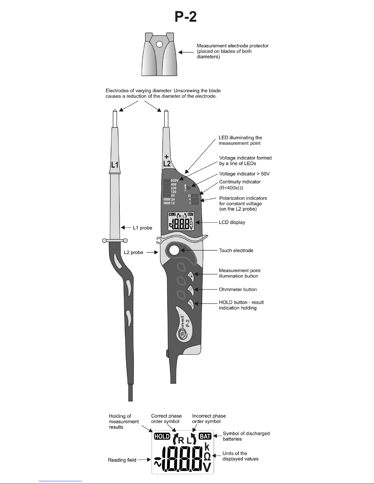
Principal characteristics of the device:
• Measurement of direct and alternative voltage
presented on a display within the range between
1.5 and 750V with the maximum exactitude of
0.1V,
• Indication of direct and alternative voltage on the
diode indicator: 12, 24, 50, 120, 230, 400, 690V,
• Indication of polarization of the direct voltage
(on the diode indicator and the display),
• The diode indicator does not require a battery,
• The one-pole voltage indicator for voltages ex-
ceeding 50V,
• Measurement of resistance within the range be-
tween 0 and 1999Ω,
• Test of continuity of the circuit with optical and
acoustic signalling,
• Function of checking the order of phases in
three-phase circuits,
• Function of test of differential current switches,
• HOLD function – holding of any measurement o
the display,
• Legible back-lit display,
• Illumination of the display connection point,
• Ergonomic and hermetic casing with elastomer
(IP65),
• Automatically switching off display in the case of
inactivity.
Page 5

3
TABLE OF CONTENTS
1
SAFETY .............................................. 4
2
MEASUREMENTS ........................... 5
2.1
CONTROL OF OPERATION OF THE
TESTER ........................................... 5
2.2
AC OR DC VOLTAGE TEST .............. 5
2.3
RCD OPERATION TEST .................... 6
2.4
ONE-POLE PHASE TESTING .............. 6
2.5
CIRCUIT CONTINUITY TEST ............. 7
2.6
MEASUREMENT OF RESISTANCE ..... 7
2.7
THE HOLD FUNCTION .................... 7
2.8
PHASE ORDER TEST ........................ 8
2.9
ILLUMINATION OF THE MEASURED
POINT ............................................. 8
3
REPLACEMENT OF THE
BATTERIES
...................................... 9
4
CLEANING AND MAINTENANCE 9
5
STORAGE .......................................... 9
6
DISMANTLING AND
UTILIZATION
................................ 10
7
TECHNICAL DATA ....................... 10
8
MANUFACTURER ......................... 12
Thank you for having purchased our voltage tester.
The P-2 tester is a modern, high-quality measurement instrument, which is easy and safe to use.
However, reading the present manual will permit you
to avoid measurement errors and prevent possible
problems regarding operation of the device.
Note:
The produce
r reserves the right to realise
modifications as regards the appearance of
the device, its equipment and technical data.
Page 6

4
1 Safety
The purpose of the P-2 device is to test voltage
and the continuity of connections as well as measurements of resistance. In order to guarantee the
correct operation of the device and correctness of
the obtained results observe the following recommendations:
• Before operation of the device starts, get your-
self acquainted with the present manual and the
safety rules and regulations as well as the recommendations specified by the manufacturer.
• Any other application of the device which has
not been determined within the present manual
may cause its damage and constitute a source
of danger for the user.
• The device should be operated solely by quali-
fied personnel who are properly authorised and
certified to realise measurements in electric installations. Should the tester be operated by unauthorised persons, there is a danger of damage to the device and the user.
• The device must not be applied to the network
and equipment within premises of special conditions, e.g. in a dangerous atmosphere with regard to explosion or fire.
• It is unacceptable to operate the following:
⇒ A damaged meter which is completely or
partially out of order,
⇒ A meter with damaged cable insulation,
⇒ A meter stored for an excessive period of
time in disadvantageous conditions (e.g. excessive humidity). If the meter has been
transferred from a cool to a warm environment of a high level of relative humidity, do
not realise measurements until the meter
has been warmed up to the ambient temperature (approximately 30 minutes).
• Do not operate a meter with an open or incor-
rectly closed battery (accumulator) compartment
or power it from other sources than those specified in the present manual.
• Do not realise measurements for more than 30
seconds. After a 30-second measurement, the
next measurement may be realised not sooner
than after 240 s.
• The purpose of the signalling of limit values is
solely to warn the user and not to realise a
measurement.
Note:
The device may also be used during rain,
however at user’s own responsibility.
It is
recommended to use gauntlets.
Page 7
5
2 Measurements
2.1 Control of operation of the
tester
Before each use of the tester, it is necessary to
control its operation:
• The voltage indicator must be tested using a
known source of voltage,
• Close the measurement probes – there should
be an audible acoustic signal, the LED Ω diode
should be on and the symbol
should ap-
pear on the display.
Remarks:
The voltage indication function is active when
the batteries are discharged or without batteries. In
order for the remaining functions to be active
charged batteries are required.
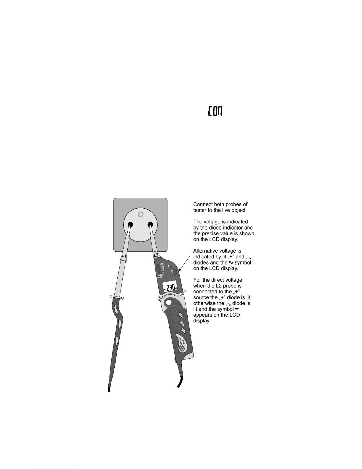
2.2 AC or DC voltage test
Note:
In the networks protected with an RCD switch
whose nominal current is 10mA or 30mA, it is possible that the switch is activated during a measure-
Page 8
6
ment of voltage between L and PE. In order to avoid
that connect the tester between L and N and after
approximately five seconds switch the probe from N
to PE.
2.3 RCD operation test
In order to check the operation of the RCD
switch whose nominal current is 10mA or 30mA it is
necessary to realise a voltage test directly between
the L phase and the protective cable PE.
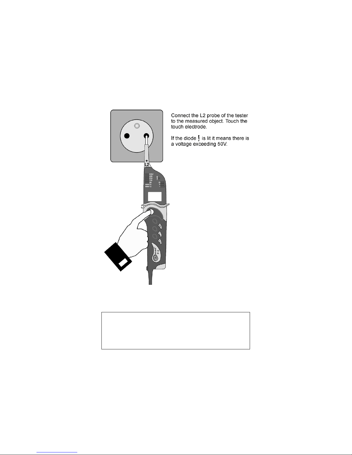
2.4 One-pole phase testing
Note:
Attention!
Do not touch the electrode of the measurement
probe L1 during the testing of the phase.
In the case of one-pole determination of phases
for the purpose of specification of external cables,
under certain circumstances it is possible that the
operation of the tester will be impaired (e.g. using
insulated personal protection means or in the case
of an insulated work station).
One-pole phase testing may not be a sufficient
means to determine whether the circuit in question
is live. Do apply the two-pole voltage test.
Page 9
7
2.5 Circuit continuity test
Note!
The measured object may be live.
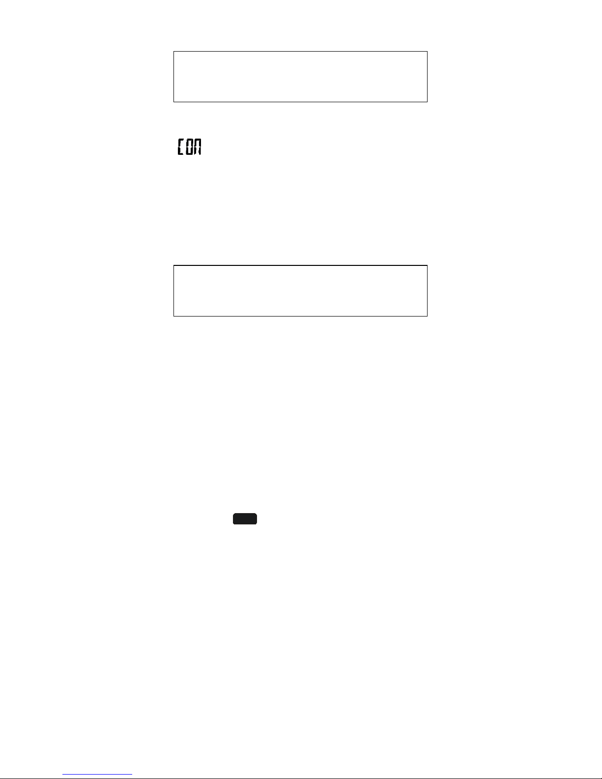
Connect both the probes to the measured object. An acoustic signal, lit Ω diode and the symbol
appearing on the display indicate continuity of
the circuit (R<600kΩ).
Note:
During the measure of continuity polarization of
the voltage at the L2 probe is negative.
2.6 Measurement of resistance
Note!
The measured object may not be live.
Press shortly the Ω button and connect both the
probes to the measured object. Read the result from
the LCD display.
Note:
During the measure of resistance polarization of
the voltage at the L2 probe is negative.
2.7 The HOLD function
The purpose of the present function is to hold
the result of the measurement o the display. It is
possible pressing the HOLD button. In the left upper
corner the
HOLD
symbol will be visible all the time
while the measuring instrument remains in this
mode.
Should the operator want to return to the normal
measurement mode, they must press the HOLD
button again.
In the HOLD mode the Auto-OFF time will be
extended to 30 seconds.
Page 10
8
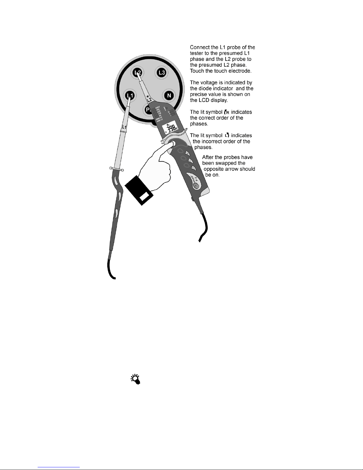
2.8 Phase order test
Note:
The order of the phases may be determined solely in a three-phase system.
2.9 Illumination of the measured
point
The P-2 tester offers the possibility of illumination of the measured area under difficult light conditions (e.g. in switchgears). In order to illuminate the
measured point press the button marked with the
symbol
. At the same time the LCD display is
backlit and it turns off automatically after approximately seven seconds.
The illumination may be also turned on when the
tester is off, and then three lines will appear on the
display.
Page 11
9
3 Replacement of the batteries
The tester is powered by means of two 1.5V
AAA batteries. A lack of acoustic signal once both
the probes have been closed, too weak illumination
after the button
has been pressed or the symbol
appearing on the display indicate the necessity
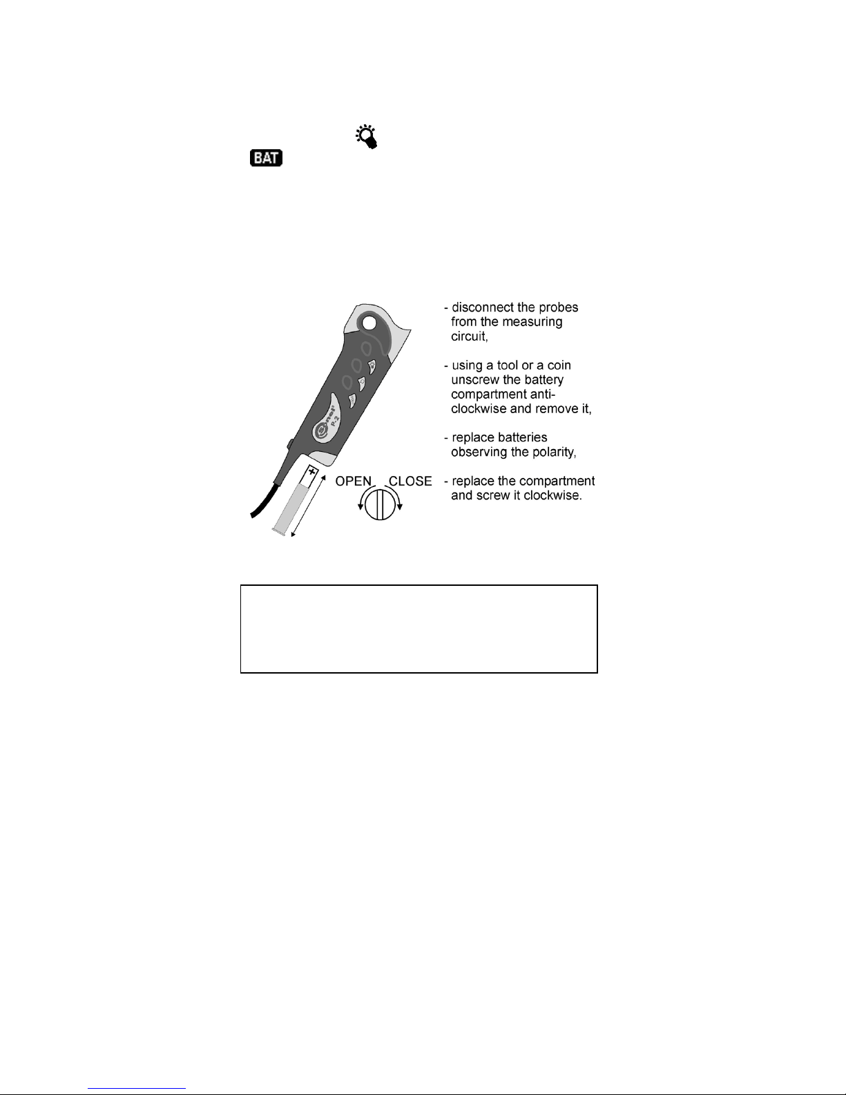
to replace the batteries. Follow the instructions below:
- disconnect the probes from the measuring circuit
- using a tool or a coin unscrew the battery compartment anti-clockwise and remove it
- replace batteries observing the polarity
- replace the compartment and screw it clockwise
4 Cleaning and maintenance
NOTE!
Use solely the method of maintenance specified
by the manufacturer in the present manual.
The tester may be cleaned with a soft, wet flannel using al-purpose detergents. Do not use any
solvents or cleansing agents which might scratch
the casing (powders, pastes, etc.).
The electronic system of the tester does not require maintenance.
5 Storage
Storing the tester observe the following recommendations:
• Place protectors on the probes,
• Make sure the tester is dry,
• In the case of prolonged periods of storage re-
move the batteries from the tester.
Page 12
10
6 Dismantling and utilization
Worn electric and electronic equipment must be
disposed of selectively, i.e. it must not be disposed
of along with waste of other kinds.
Send worn electronic equipment to a collection
point in accordance with the act on worn electric and
electronic equipment.
Before sending the equipment to a collection
point do not dismantle any components of the
equipment.
Observe local regulations regarding disposal of
packages, discharged batteries and accumulators.
7 Technical data
The symbol „d.v.” in the case of determination of
the fundamental uncertainty means the displayed
value.
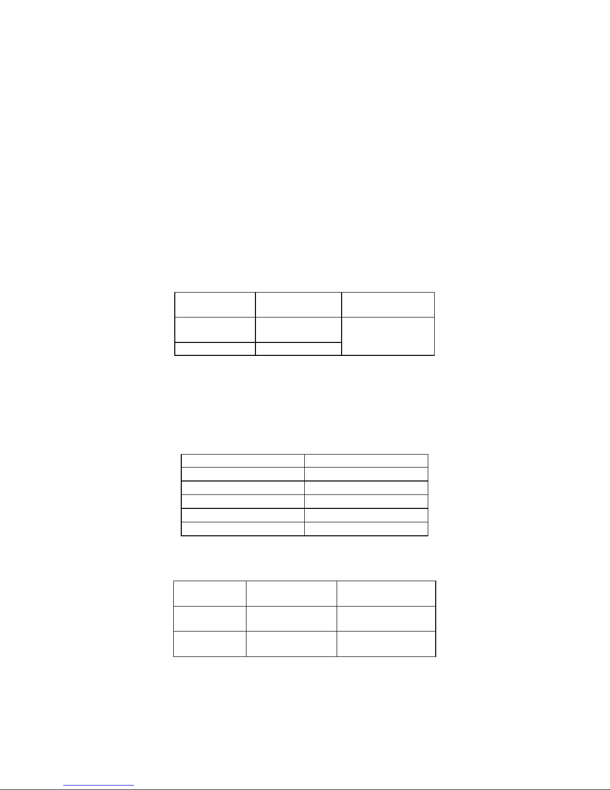
Measurement of direct voltage (on the display):
* - from 6,0V for Sr. no. up to 663530
Furthermore the voltage is indicated by the diode
indicator for the following values: 12, 24, 50, 120,
230, 400, 690V along with the signalling of the polarization of voltage (the diodes „+” or „-” are on).
The diode indicator functions also without batteries.
Input resistance
Uin
Rin
12V, 24V, 50V
~ 6kΩ
120V
~ 20kΩ
230V
~ 70kΩ
400V
~ 150kΩ
690V
~ 240kΩ
Measurement of alternative voltage within the
range between 20 and 400Hz (on the display):
* - from 6,0V for Sr. no. up to 663530
Furthermore the voltage is indicated by the diode
indicator for the following values: 12, 24, 50, 120,
230, 400, 690V along with the signalling of the polarization of voltage (the diodes „+” or „-” are on).
The diode indicator functions also without batteries.
Range Exactitude
Fundamental
uncertainty
+1,5/-2,5*
...49,9V
0,1V
±(2% d.v. +
3 digits)
50...750V
1V
Range Exactitude
Fundamental un-
certainty
1,5*...49,9V 0,1V
±(3% d.v. +
4 digits )
50...750V 1V
±(2% d.v. +
3 digits )
Page 13

11
The frequency of the measurement voltage for the
diode indicator: 15…400Hz.
Measurement of resistance:
Range Exactitude
Fundamental
uncertainty
0...1999Ω 1Ω
±(3% d.v. +
8 digits)
Other data:
a) Kind of insulation: double, in accordance with
EN 61010-1
b) Measurement category: III 1000V (IV 600V) in
accordance with EN 61010-1
c) Protection grade for the casing in accordance
with EN 60529: IP65
d) Range of voltage measurement on the LCD dis-
play: 6…750V AC/DC
e) Indication of voltage on the diode indicator:
12V, 24V, 50V, 120V, 230V, 400V, 690V
f) Minimum voltage at which the indicator turns on:
6V
g) Exactitude of voltage indications: in accordance
with EN 61243-3
h) Range of voltage frequency for the LCD display:
20…400Hz
i) Range of voltage frequency for the diode indica-
tor: 15…400Hz
j) Maximum current: I
S
<0,2A/IS(5s)<3,5mA
k) Maximum time of continuous operation: 30s
l) Minimum break for a 30-second operation time:
240s
m) Range of voltage for a one-pole phase indicator:
50…690V
n) Range of frequencies for a one-pole phase indi-
cator: 50…400Hz
o) Range of the continuity tester: 0…600kΩ
(400kΩ for Sr. no. up to 663530)
p) Exactitude of the activation threshold for the
continuity tester: ±50%
q) Measurement current for the continuity tester:
7μA
r) Range of voltage for a two-pole phase order in-
dicator: 100…690V
s) Range of frequencies for a two-pole phase order
indicator: 50…60Hz
t) Auto-OFF time: approximately 7s (30s in the
HOLD mode)
u) Display: LCD 3 1/2 digits
v) Power supply for the measuring device: 2x1,5V
size AAA/LR03 (recommended alkaline)
w) Dimensions: approximately 240x60x30 mm
x) Mass of the tester with batteries: approximately
0,2kg
y) Working temperature: -10..+55°C
z) Storage temperature: -30..+70°C
Page 14

12
aa) Quality standard: development, design and
manufacture in accordance with ISO 9001
bb) the product meets the EMC requirements (im-
munity for industrial environment) according to
the following standards EN 61326-1:2006 and
EN 61326-2-2:2006
8 Manufacturer
The manufacturer of the instrument who provides guarantee and post-guarantee service is:
SONEL S.A.
ul. Wokulskiego 11
58-100 Świdnica
Poland
tel. +48 74 858 38 60
fax +48 74 858 38 09
E-mail:
Web page:
www.sonel.pl
Note:
The device may be repaired solely by the manufacturer.
Page 15

Page 16

 Loading...