

Page 1
Page 2
Page 3

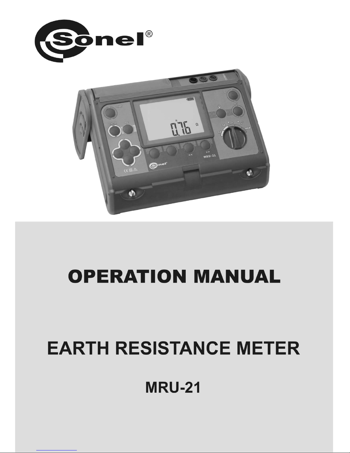
OPERATING MANUAL
Earth Resistance Meter
MRU-21
SONEL SA
ul. Wokulskiego 11
58-100 Świdnica, Poland
Version 1.04 28.04.2017
Page 4

OPERATING MANUAL MRU-21 version 1.04
2
The MRU-21 meter is a modern, easy and safe measuring device. Please acquaint yourself with the
present manual in order to avoid measuring errors and prevent possible problems related to operation
of the meter.
Page 5

OPERATING MANUAL MRU-21 version 1.04
3
CONTENTS
1 SAFETY .................................................................................................................... 5
2 SETTINGS ................................................................................................................ 6
3 MEASUREMENTS .................................................................................................. 7
3.1 EARTH RESISTANCE MEASUREMENT WITH THE THREE-LEAD METHOD ................... 7
3.2 EARTH RESISTANCE MEASUREMENT WITH THE DOUBLE-LEAD METHOD .............. 10
3.3 MEASUREMENT OF RESISTANCE OF PROTECTIVE CONDUCTORS AND
EQUIPOTENTIAL BONDING ................................................................................... 12
3.4 CALIBRATION OF TEST LEADS .............................................................................. 14
3.4.1 Turning AUTOZERO on .............................................................................. 14
3.4.2 Turning AUTOZERO off .............................................................................. 15
4 MEMORY ............................................................................................................... 16
4.1 STORING THE MEASUREMENT RESULT DATA IN THE MEMORY ............................. 16
4.2 VIEWING MEMORY DATA ..................................................................................... 18
4.3 DELETING MEMORY DATA ................................................................................... 18
4.3.1 Deleting bank data....................................................................................... 18
4.3.2 Deleting the whole memory ......................................................................... 20
4.4 COMMUNICATION WITH A COMPUTER ................................................................. 21
4.4.1 Computer connection accessories ............................................................... 21
4.4.2 Data transmission ........................................................................................ 21
5 METER POWER SUPPLY ................................................................................... 22
5.1 MONITORING OF THE POWER SUPPLY VOLTAGE ................................................... 22
5.2 REPLACEMENT OF BATTERIES ............................................................................. 22
6 CLEANING AND MAINTENANCE .................................................................... 25
7 STORAGE .............................................................................................................. 25
8 DISMANTLING AND UTILIZATION ................................................................ 25
9 TECHNICAL SPECIFICATIONS ....................................................................... 26
9.1 BASIC DATA ........................................................................................................ 26
9.2 ADDITIONAL INFORMATION ................................................................................. 28
9.2.1 RE measurement ........................................................................................... 28
9.2.2 R
CONT
measurement ...................................................................................... 29
10 EQUIPMENT ......................................................................................................... 30
10.1 STANDARD EQUIPMENT ....................................................................................... 30
Page 6

OPERATING MANUAL MRU-21 version 1.04
4
10.2 OPTIONAL ACCESSORIES ..................................................................................... 30
11 MANUFACTURER ............................................................................................... 31
Page 7

OPERATING MANUAL MRU-21 version 1.04
5
1 Safety
MRU-21 meter is designed for measuring parameters important for safety of electrical
installations. Therefore in order to provide conditions for correct operation and the correctness of the
obtained results, the following recommendations must be observed:
Before you proceed to operate the meter, acquaint yourself thoroughly with this manual and
observe the safety regulations and specifications defined by the producer.
MRU-21 meter is designed to measure earth resistance and the resistance of protective
conductors and equipotential bondings. Any application that differs from those specified in the
present manual may result in a damage to the device and constitute a source of danger for the
user.
The meter must be operated solely by appropriately qualified personnel members holding
required certificates for carrying measurements in electric installations. Unauthorized use of the
meter may result in its damage and may seriously endanger unauthorized user.
Using this manual does not exclude the need to comply with occupational health and safety
regulations and with other relevant fire regulations required during the performance of a particular
type of work. Before starting the work with the device in special environments, e.g. potentially firerisk/explosive environment, it is necessary to consult it with the person responsible for health and
safety.
It is unacceptable to operate the following:
a damaged meter which is completely or partially out of order,
a meter with damaged test leads insulation,
a meter stored for an excessive period of time in disadvantageous conditions (e.g. excessive
humidity).If the meter has been transferred from a cool to a warm environment of a high level
of relative humidity, do not carry out measurements until the meter is warmed up to the
ambient temperature (approximately 30 minutes).
Before commencing measurements, make sure the test leads are connected to the appropriate
measurement sockets.
Do not operate a meter with an open or incorrectly closed battery compartment or power it from
sources other than those specified in this manual.
The inputs of the meter are protected electronically against overload e.g. due to having been
connected to a live circuit:
- for all combinations of inputs - up to 276V for 30 seconds.
Repairs may be carried out only by an authorized service point.
The device meets the requirements of standards EN 61010-1 and EN 61557-1, -4, -5.
Attention:
The manufacturer reserves the right to introduce changes in appearance,
equipment and technical data of the meter.
Note:
An attempt to install drivers in 64-bit Windows 8 may result in displaying
"Installation failed" message.
Cause: Windows 8 by default blocks drivers without a digital signature.
Solution: Disable the driver signature enforcement in Windows.
Page 8
OPERATING MANUAL MRU-21 version 1.04
6
2 Settings
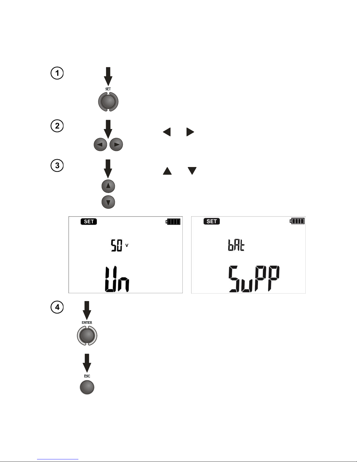
Press the SET button to select the test voltage (Un) or power supply source (SuPP). After
replacing the batteries, always set the power supply type. The correct charge indication depends on
this setting (the discharge characteristics of disposable and rechargeable batteries are different).
Turn on the meter and press SET.
Use the and buttons to select the parameter: Un or
SuPP.
Use the and buttons to change the parameters: Un
= 25V or 50V, SuPP = bAt (disposable batteries) or Acc
(rechargeable batteries).
Press ENTER to validate the changes and exit the mode, or...
...press ESC to exit the setting mode without validating the changes.
Page 9
OPERATING MANUAL MRU-21 version 1.04
7
3 Measurements
3.1 Earth resistance measurement with the three-lead method
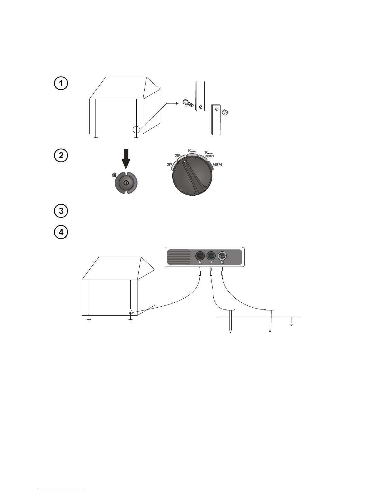
The three-lead measuring method is the basic type of resistance-to-earth measurement.
Disconnect the tested
earth electrode from the
installation of the facility.
Turn on the meter.
Turn the rotary switch
to the RE 3p position.
If necessary, adjust the voltage measurement according to section 2.
2,2m
CAT IV 300V
E S H
The current electrode (driven into earth) should be connected to H socket of the meter.
The voltage electrode (driven into earth) should be connected to S socket of the meter.
The tested earth electrode should be connected to E socket of the meter.
The tested earth electrode and the current electrode and the voltage electrode should be
aligned.
Page 10
OPERATING MANUAL MRU-21 version 1.04
8
The meter is ready
for measurement.
Read the
interference voltage
on the auxiliary
display.
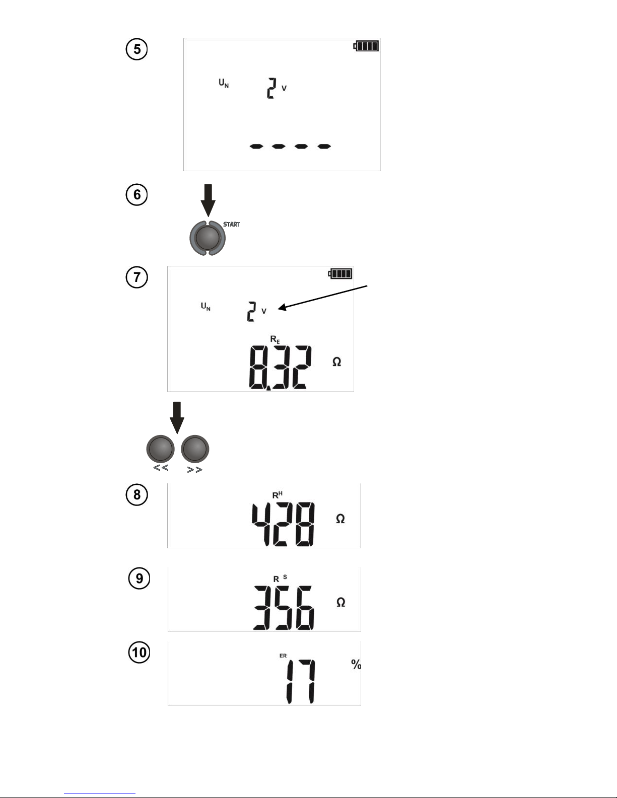
Press START.
Perform the measurement.
Interference voltage.
Read the main
measurement result.
Resistance of earth
electrode RE.
Read the auxiliary results (sequence as
below) by pressing << and >>.
RH
Resistance of current
electrode
RS
Resistance of voltage
electrode
Additional uncertainty
caused by resistance of
the electrodes.
Measur
ement
of RE
3p
Reading
the
results.
Measur
ement
of RE
3p
Reading
the
results.
Page 11
OPERATING MANUAL MRU-21 version 1.04
9
S
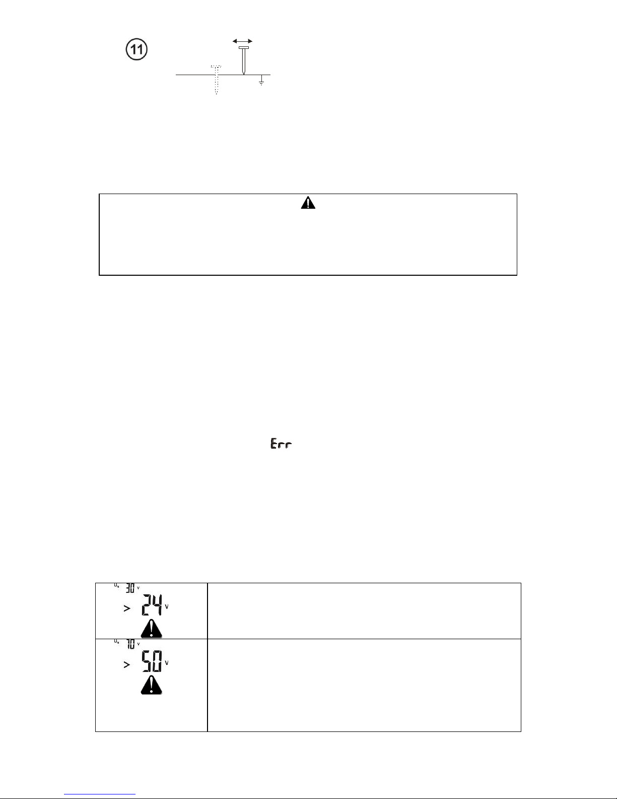
Repeat the measurements (steps 3-6)
after moving the voltage a few meters placing it farther and closer to the
measured earth electrode. If the R
E
measurement results differ by more than
3%, the distance of the current electrode
from the tested earth electrode should be
considerably increased and the
measurements should be repeated.
Note:
The earth resistance measurement can be made when the interference voltage
does not exceed 24V. The voltage is measured up to 100V, but above 50V is
indicated as dangerous. The meter must not be connected to voltages
exceeding 100 V.
- Particular attention should be paid to quality of connection between the tested facility and the test
lead – the contact area must be free from paint, rust, etc.
- If resistance of the test probes is too high, RE earth electrode measurement will include an additional
uncertainty. Particularly high measurement uncertainty occurs when a small value of resistance to
earth is measured with probes that have a weak contact with earth (such a situation occurs frequently
when the earth electrode is well made and the upper soil layer is dry and poorly conductive). In such a
case, the ratio of resistance of the probes to resistance of the tested earth electrode is very high and
consequently, uncertainty of measurement that depends on this ratio is also very high. Then, you can
make a calculation according to the formulas given in item 9 to estimate the influence of
measurement conditions, or you can use the graph also included in the appendix. This uncertainty is
also displayed in [%] as an additional result. It is calculated on the basis of measured valued. If such
additional uncertainty exceeds 30% the symbol is displayed You can improve the contact
between the probe and soil, for example by dampening with water the place where the probe is driven
into earth, driving the probe into earth in a different place, or using a 80 cm-long probe. Check also
the test leads for possible insulation damage and for corroded or loosened connection between the
banana plug and the test lead. In majority of cases the measurement accuracy achieved is
satisfactory. However, one should always be aware of the uncertainty included in the measurement.
- Factory calibration includes the resistance of the 2.2 m test lead (supplied).
Additional information displayed by the meter
and
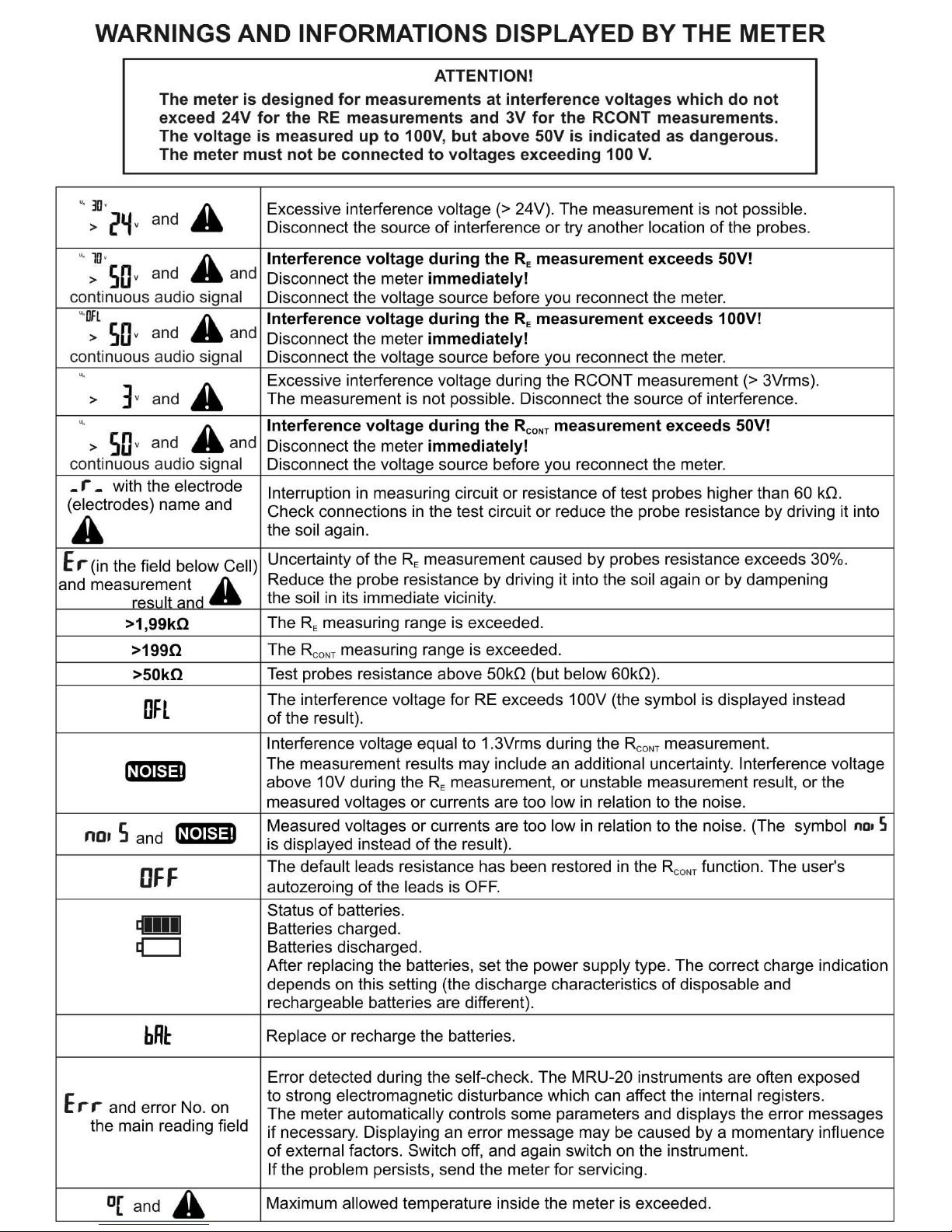
Excessive interference voltage (> 24V). The measurement is
not possible.
Disconnect the source of interference or try another location of
the probes.
and
and continuous
audio signal
Interference voltage exceeds 50V!
Disconnect the meter immediately!
Disconnect the voltage source before you reconnect the
meter.
Page 12
OPERATING MANUAL MRU-21 version 1.04
10
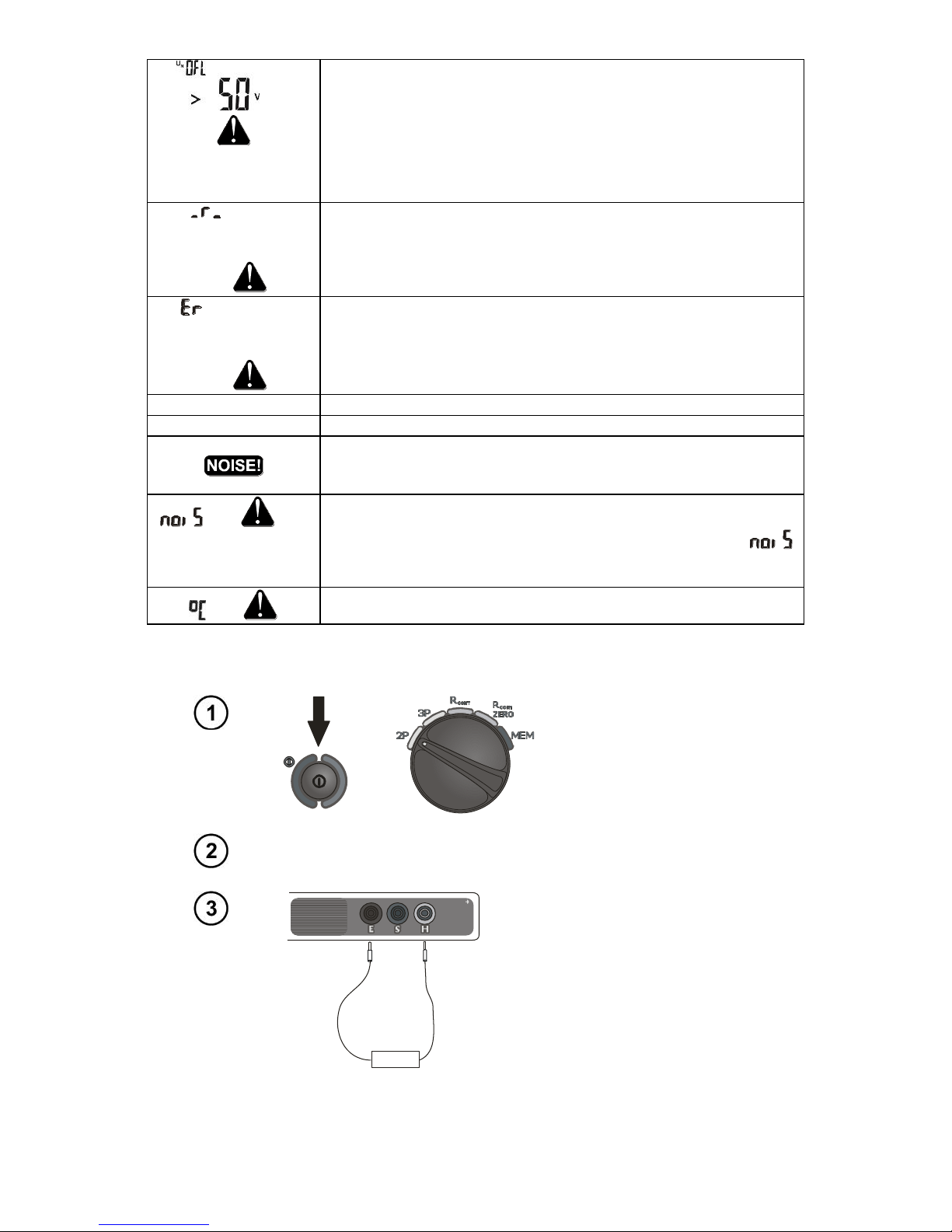
and
and continuous
audio signal
Interference voltage exceeds 100V!
Disconnect the meter immediately!
Disconnect the voltage source before you reconnect the
meter.
with the
electrode
(electrodes) name
and
Interruption in measuring circuit or resistance of test probes
higher than 60 kΩ.
Check connections in the test circuit or reduce the probe
resistance by driving it into the soil again.
(in the field
below Cell) and
measurement result
and
Uncertainty of the RE measurement caused by probes
resistance exceeds 30%. Reduce the probe resistance by
driving it into the soil again or by dampening the soil in its
immediate vicinity.
>1,99kΩ
The RE measuring range is exceeded.
>50kΩ
Test probes resistance above 50kΩ (but below 60kΩ).
Interference voltage above 10V, or unstable measurement
result, or the measured voltages or currents are too low in
relation to the noise.
and and
long audio signal
Measured voltages or currents are too low in relation to the
noise, or highly unstable measurement result. (The
symbol is displayed instead of the result).
and
Maximum allowed temperature inside the meter is exceeded.
3.2 Earth resistance measurement with the double-lead method
Turn on the meter.
Turn the rotary switch
to the RE 2p position.
If necessary, adjust the voltage measurement according to section
2.
2,2m
1,2m
CAT IV 300V
E H
Connect the tested
facility to the E and H
terminals.
Page 13
OPERATING MANUAL MRU-21 version 1.04
11
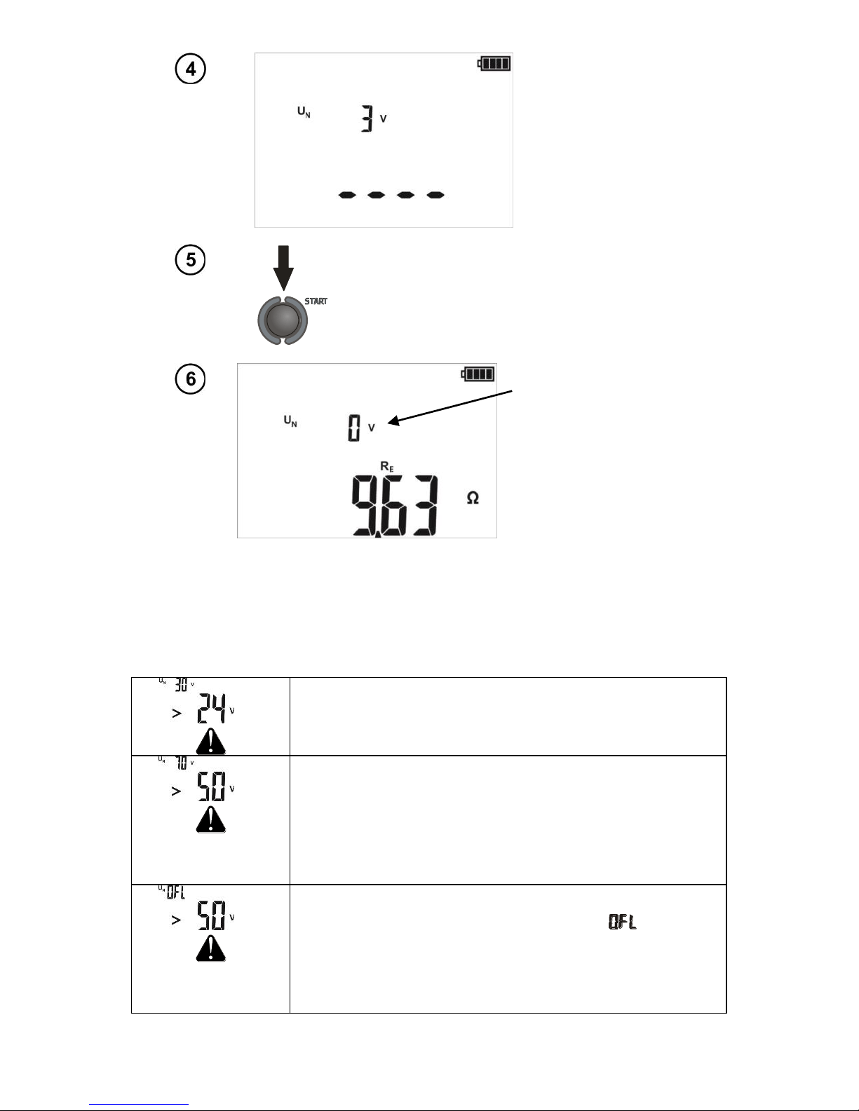
The meter is ready
for measurement.
Read the interference
voltage on the
auxiliary display.
Press START.
Perform the measurement.
Interference voltage.
Read the measurement
result.
Measured resistance.
Note:
- Factory calibration includes the resistance of the 1.2 m and 2.2 m test leads (supplied).
Additional information displayed by the meter
and
Excessive interference voltage (> 24V). The measurement is
not possible.
Disconnect the source of interference.
and
and continuous
audio signal
Interference voltage exceeds 50V!
Disconnect the meter immediately!
Disconnect the voltage source before you reconnect the
meter.
and
and continuous
audio signal
Interference voltage exceeds 100V!
Disconnect the meter immediately! (The symbol is
displayed instead of the interference voltage).
Disconnect the voltage source before you reconnect the
meter.
Page 14
OPERATING MANUAL MRU-21 version 1.04
12
and
Interruption in the test circuit.
>1,99kΩ
The RE measuring range is exceeded.
Interference voltage above 10V, or unstable measurement
result, or the measured voltages or currents are too low in
relation to the noise.
and and
long audio signal
Measured voltages or currents are too low in relation to the
noise, or highly unstable measurement result. (The
symbol is displayed instead of the result).
and
Maximum allowed temperature inside the meter is exceeded.
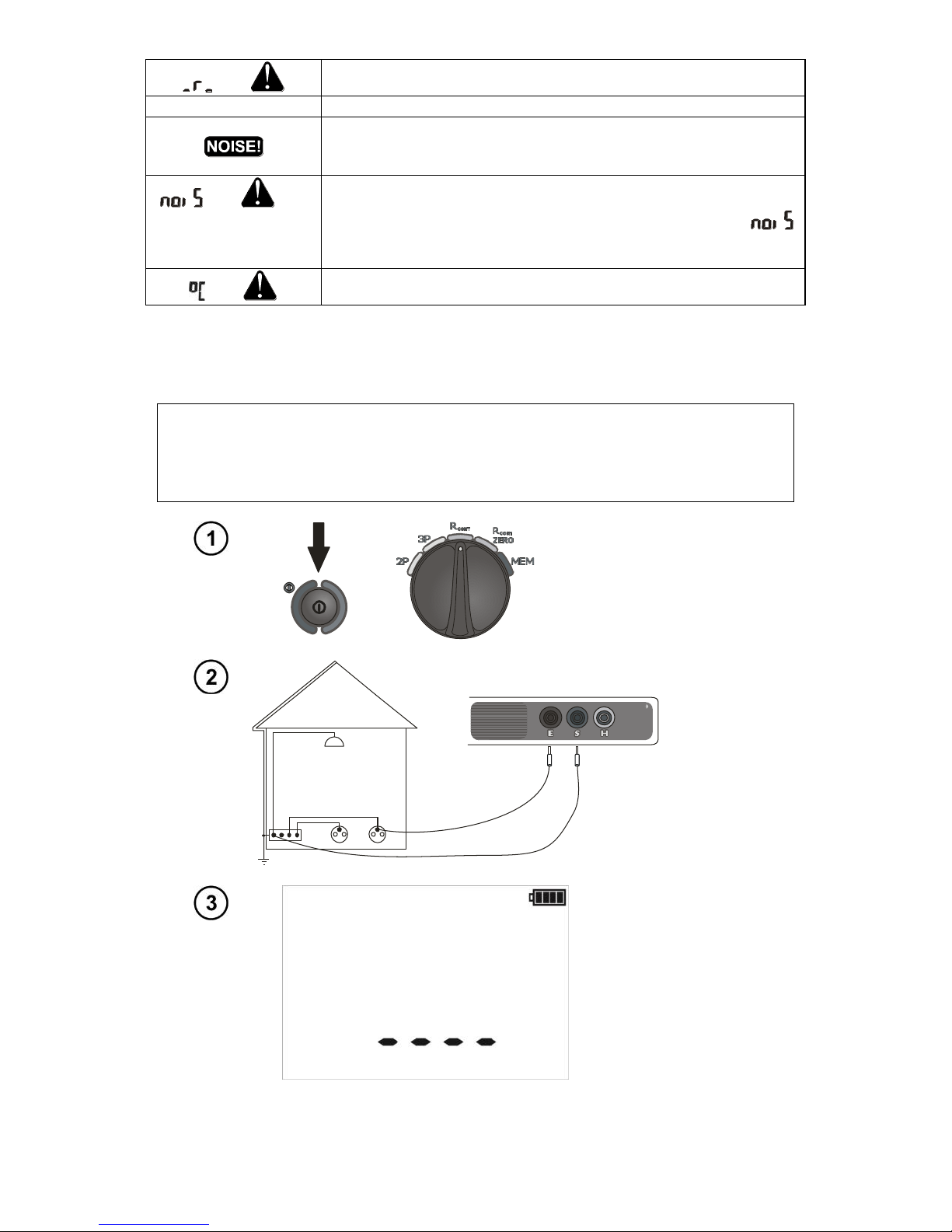
3.3 Measurement of resistance of protective conductors and
equipotential bonding
NOTE
Calibrate the test leads when measuring very small resistance values or when using
test leads different than the supplied 1.2 m and 2.2 m.
Turn on the meter.
Turn the rotary switch
to the R
CONT
position.
2,2m
1,2m
CAT IV 300V
E
S
Connect
the tested
facility
to the S
and E
terminals.
The meter is ready
for measurement.
Page 15
OPERATING MANUAL MRU-21 version 1.04
13
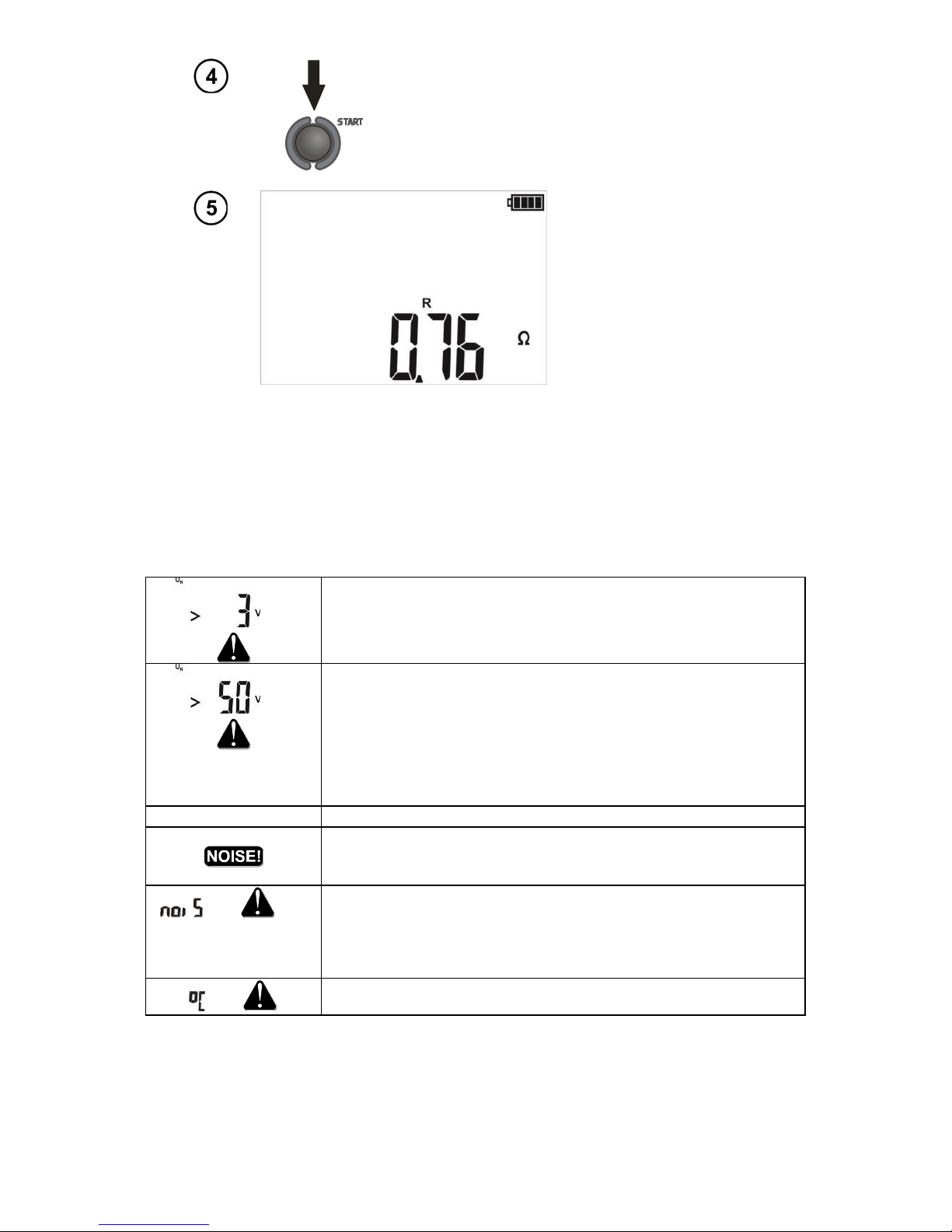
Press START.
Perform the measurement.
Read the measurement
result.
Note:
- The test current flows in one direction. To obtain the result for both directions, switch the test leads
and perform the measurement again, then calculate the arithmetic mean of both results.
Additional information displayed by the meter
and
Excessive interference voltage (> 3Vrms). The measurement
is not possible.
Disconnect the source of interference.
and
and continuous
audio signal
Interference voltage exceeds 50V!
Disconnect the meter immediately!
Disconnect the voltage source before you reconnect the
meter.
> 199Ω
The R
CONT
measuring range is exceeded.
1..3Vrms interference voltage during the R
CONT
measurement.
Measurement is slightly unstable. The results may include an
additional uncertainty.
and and
long audio signal
Measurement is highly unstable.
and
Maximum allowed temperature inside the meter is exceeded.
Page 16
OPERATING MANUAL MRU-21 version 1.04
14
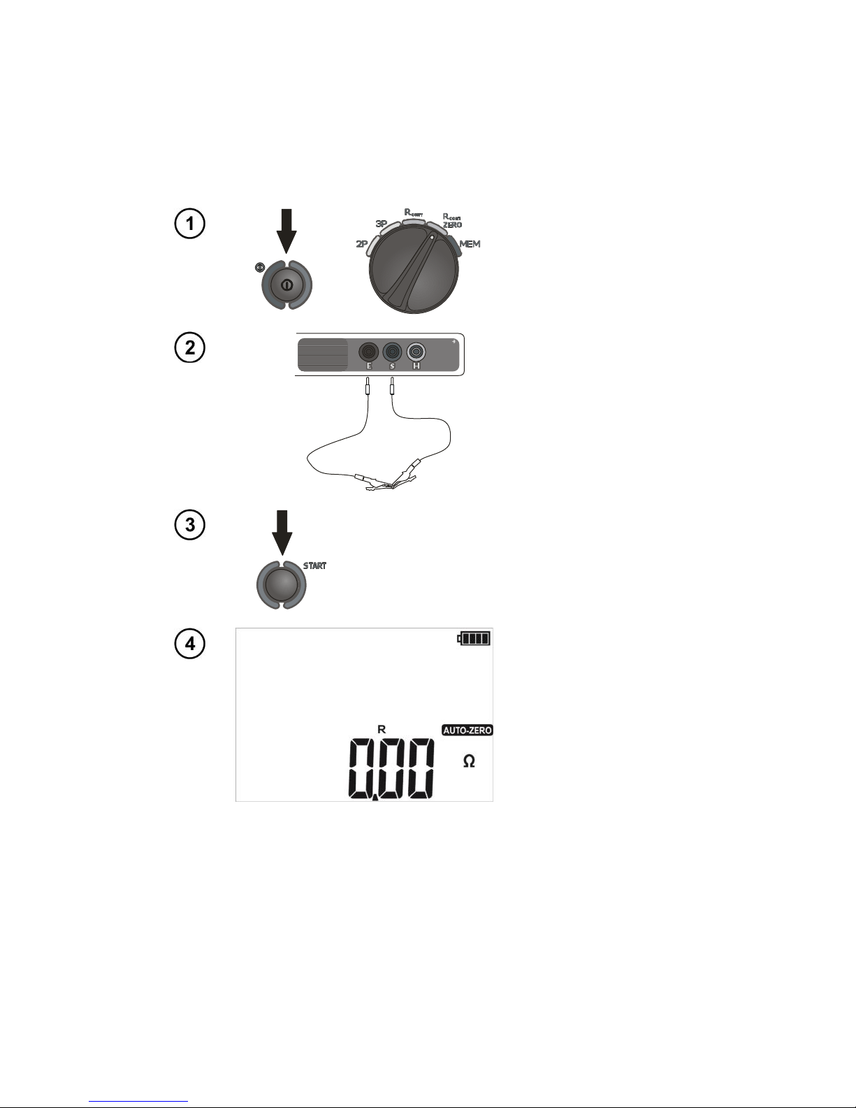
3.4 Calibration of test leads
In order to eliminate the impact of the resistance of test leads on the measurement result, the
compensation (autozeroing) of resistance may be performed. This is made with the AUTOZERO
function in the Rcont measurement.
3.4.1 Turning AUTOZERO on
Turn on the meter.
Turn the rotary switch
to the the R
CONT
ZERO
position.
CAT IV 300V
E S
Short the test leads by
putting crocodile clips
on exposed ends of the
test leads.
Press START.
Perform autozeroing.
Autozeroing
completed.
Note:
- Remember that the resistance of crocodile clips and crocodile-banana connections is added to the
resistance of the test leads.
Page 17
OPERATING MANUAL MRU-21 version 1.04
15
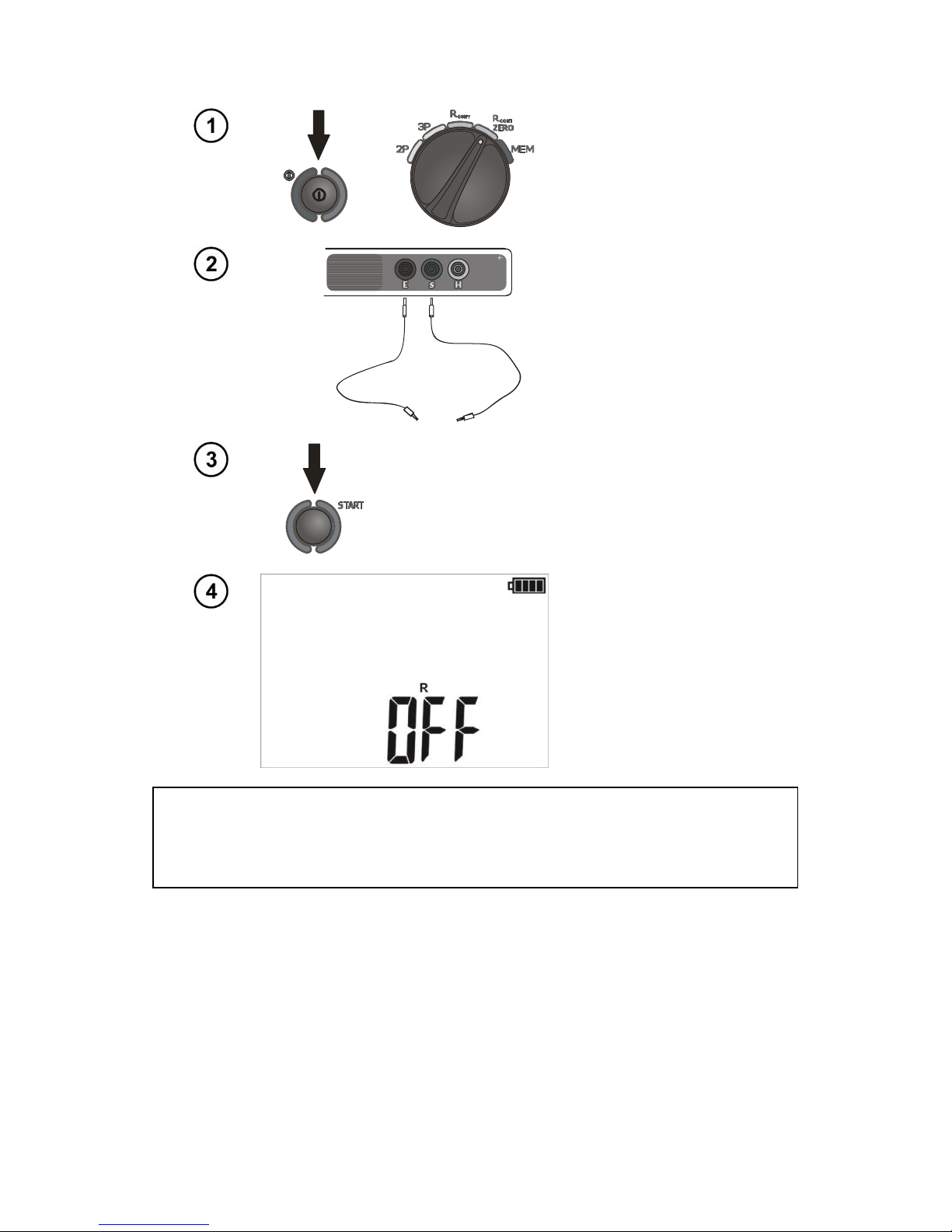
3.4.2 Turning AUTOZERO off
Turn on the meter.
Turn the rotary switch
to the the R
CONT
ZERO
position.
CAT IV 300V
E S
Disconnect the test
leads.
Press START.
Autozeroing is off.
During the
measurements, the
meter will compensate
the resistance of the
supplied 1.2 m and 2.2
m leads.
NOTE
It suffices when the compensation for given test leads is performed only once.
It is remembered when the meter is turned off.
Page 18
OPERATING MANUAL MRU-21 version 1.04
16
4 Memory
The MRU-21 meters feature memory that can store 990 single measurement results The whole
memory is divided into 10 memory banks, with 99 cells in each bank. Each measurement result can
be stored in a memory cell marked with a selected number and in a selected memory bank. Thanks to
this, the user of the meter can, at his/her option, assign memory cell numbers to individual
measurement points and the memory bank numbers to individual facilities. The user can also perform
measurements in any sequence and repeat them without losing other data.
Memory of measurement result data is not deleted when the meter is switched off. Thanks to
this, the data can be later read or sent to a computer. The number of a current memory cell or
memory bank is not changed either.
Note:
- One cell can contain the results of a single measurement.
- After each entry of the measurement result to the cell, its number is automatically incremented.
- It is recommended to delete the memory after reading the data or before performing a new series of
measurements that may be stored into the same memory cells as the previous ones.
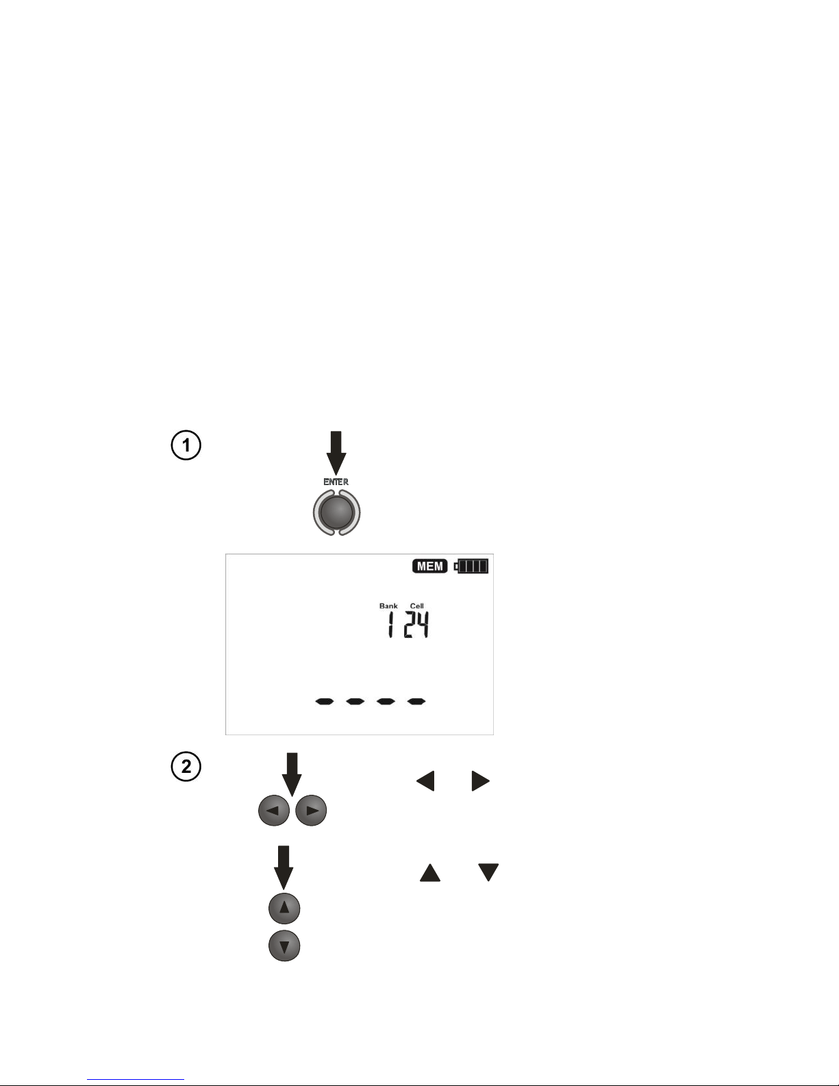
4.1 Storing the measurement result data in the memory
Press ENTER after completion of
the measurement.
The meter is in the memory
storing mode.
Cell is empty.
Use the and symbols to select the
bank...
or use the and symbols to select the
cell.
Page 19
OPERATING MANUAL MRU-21 version 1.04
17
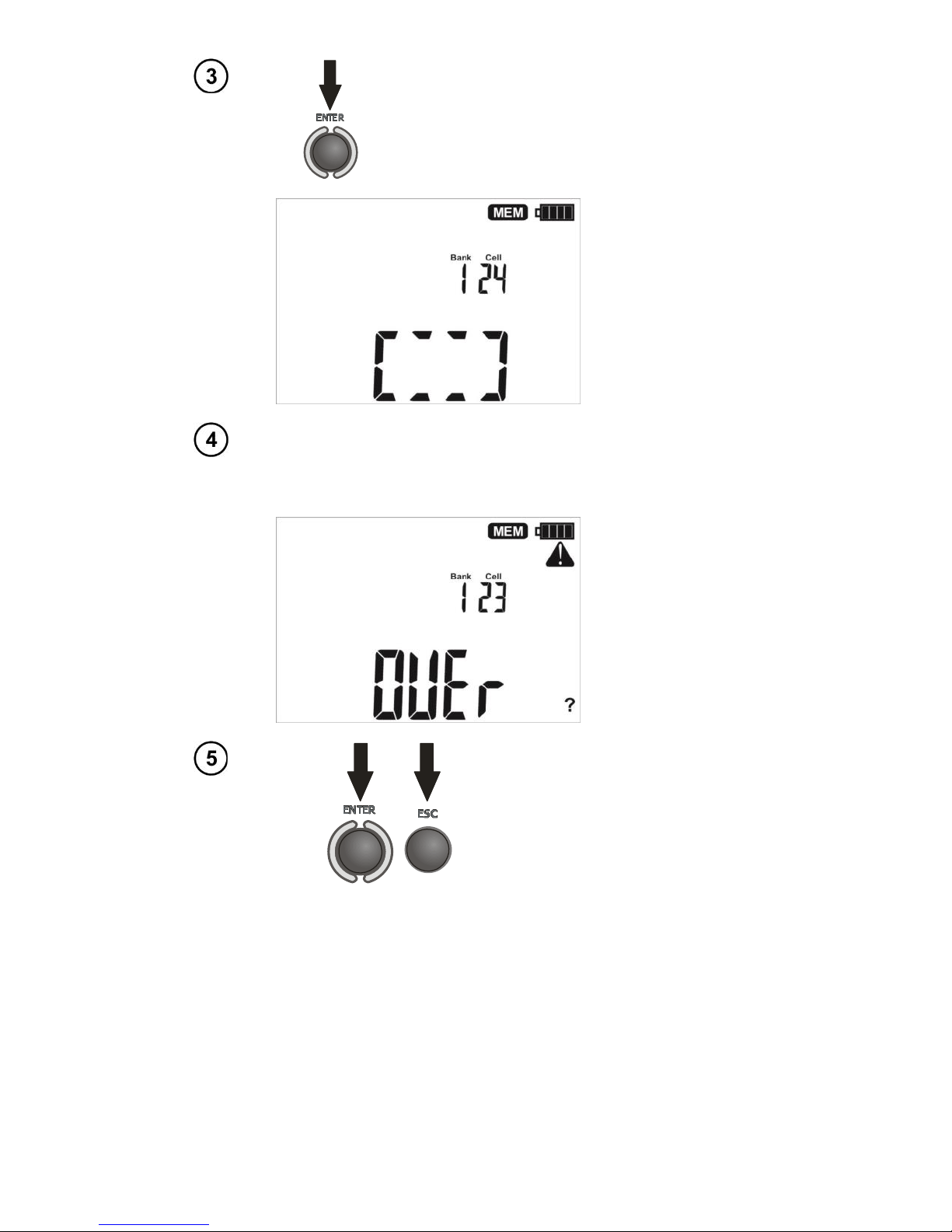
Press ENTER again. The screen (shown below)
appears for a moment, accompanied by three
short beeps, and then the meter returns to
display the last result of the measurement.
An attempt to overwrite a result causes
the warning symbol to appear.
lub
Press ENTER to overwrite the
result or ESC to abort.
Note:
- Stored in the memory is a complete set of results (main result and supplementary results), as well
as the test voltage for RE.
Page 20
OPERATING MANUAL MRU-21 version 1.04
18
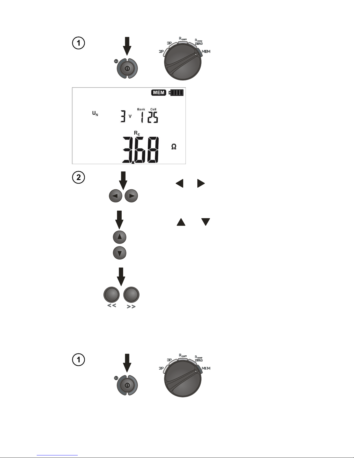
4.2 Viewing memory data
Turn on the meter.
Turn the rotary switch
to the MEM position.
The content of the last saved
cell appears.
Use the and symbols to select the
bank...
or use the and symbols to select the
cell.
Press << or >> to view additional results.
4.3 Deleting memory data
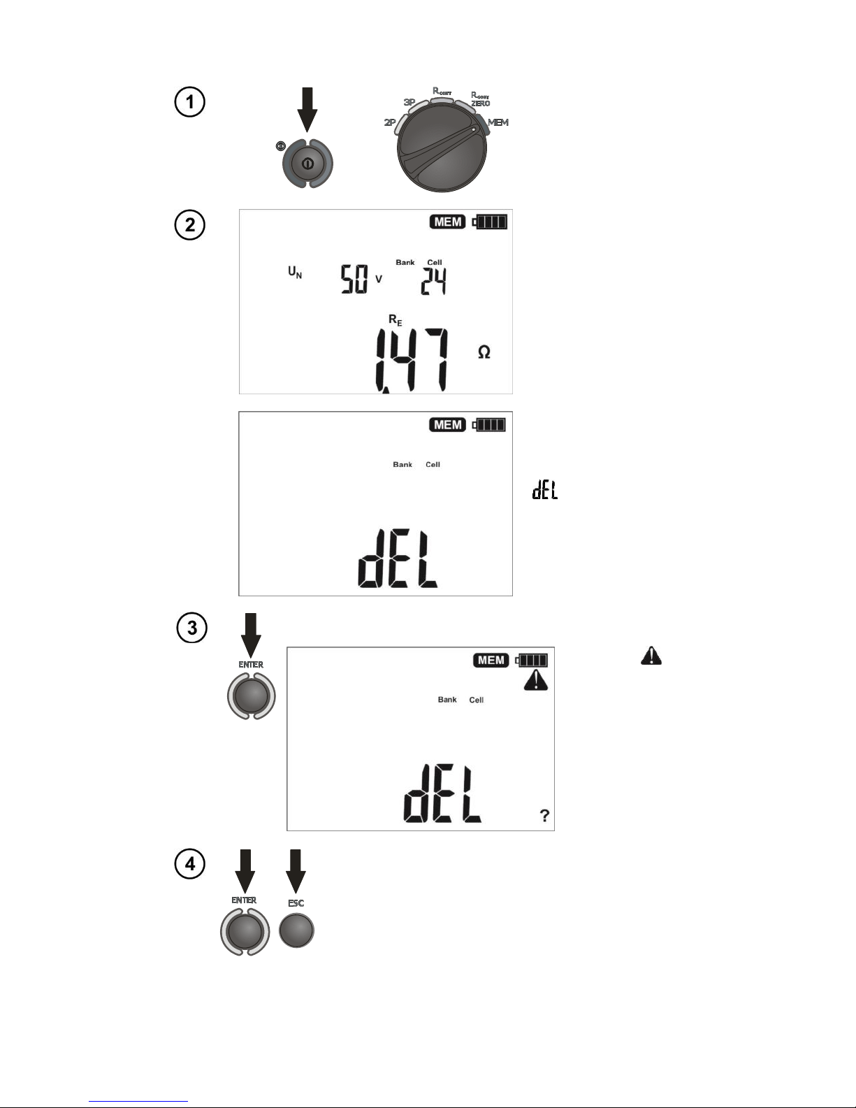
4.3.1 Deleting bank data
Turn on the meter.
Turn the rotary switch
to the the MEM
position.
Page 21
OPERATING MANUAL MRU-21 version 1.04
19
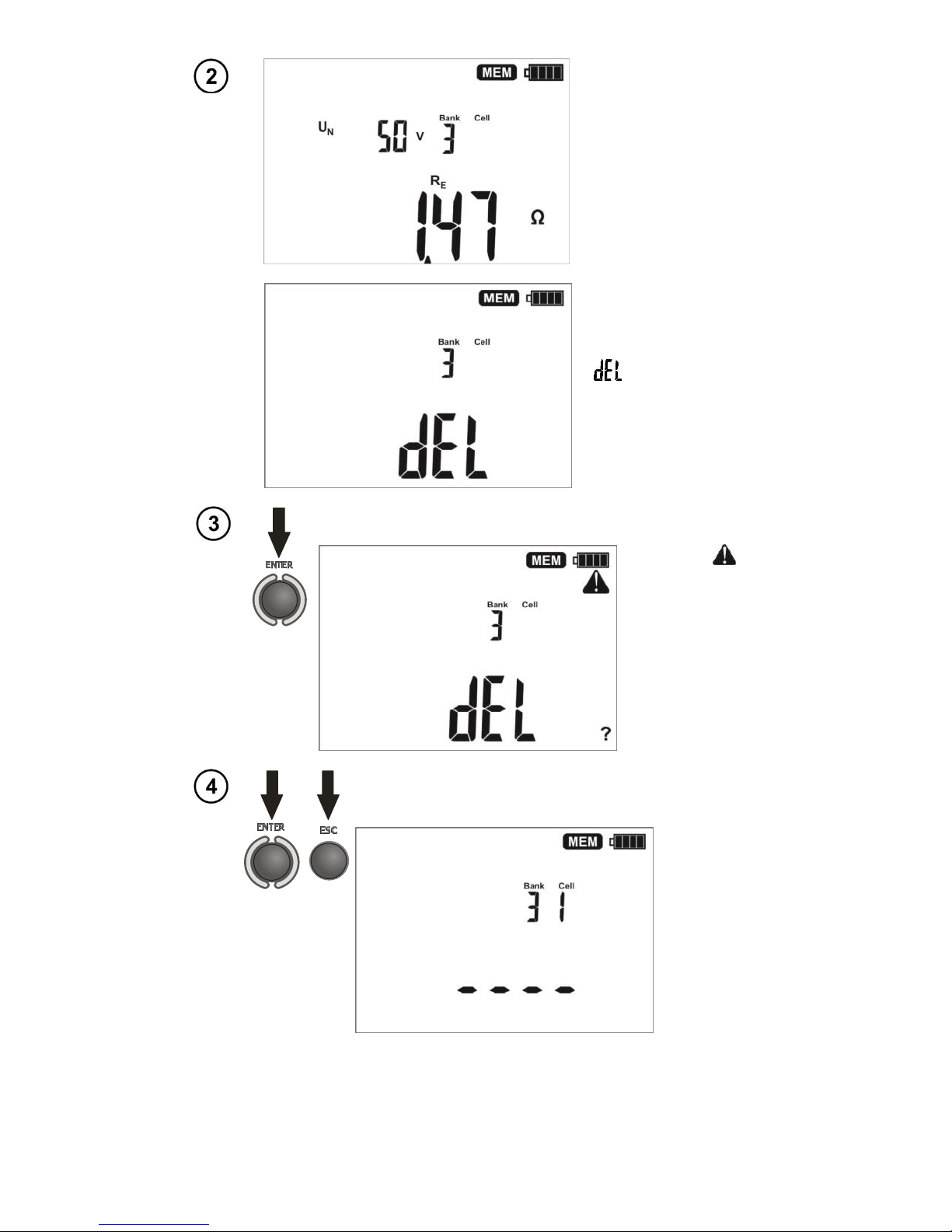
Set the bank number
to be deleted.
Set the cell number
before “1”...
...the cell number
disappears, and
appears the symbol
indicating the
readiness to delete.
Press ENTER .
The “?” and
symbols appear,
asking you to
confirm deletion.
lub
Press ENTER to start deleting or ESC
to abort.
The deletion
progress is
shown on the
display as
dashes (each
dash means
25%). When
deletion is
complete, the
meter
generates
three short
beeps and
sets the cell
number to "1".
Page 22
OPERATING MANUAL MRU-21 version 1.04
20
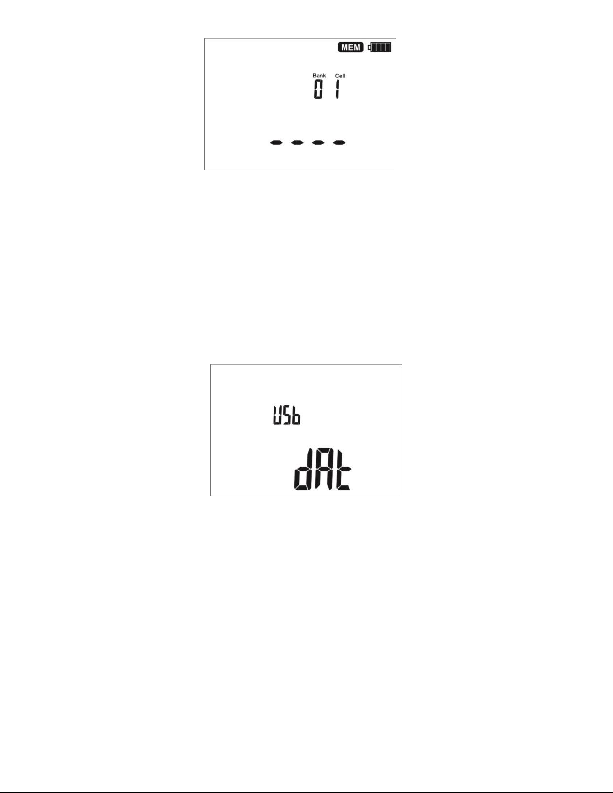
4.3.2 Deleting the whole memory
Turn on the meter.
Turn the rotary switch
to the MEM position.
Set the bank number
between “0” and “9”...
...the bank number
disappears, and
appears the symbol
, indicating the
readiness to delete.
Press ENTER .
The “?” and
symbols appear,
asking you to
confirm deletion.
lub
Press ENTER to start deleting or
ESC to abort.
The deletion
progress is shown
on the display as
dashes (each dash
means 25%).
Page 23
OPERATING MANUAL MRU-21 version 1.04
21
When deletion is
complete, the
meter generates
three short beeps
and sets the bank
number to "0" and
the cell number to
"1".
4.4 Communication with a computer
4.4.1 Computer connection accessories
What is necessary in order to operate the meter with a computer is additional accessories,
namely a cable for serial transmission and appropriate software. If this package has not been
purchased along with the meter, it can be bought from the manufacturer or an authorized distributor
where detailed software information is also available.
4.4.2 Data transmission
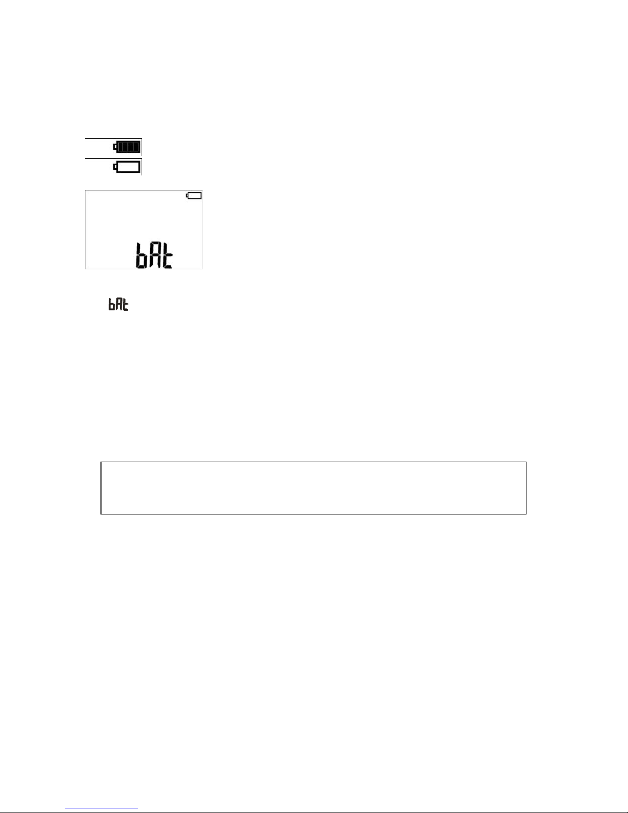
If the rotary switch is in the MEM position, after detecting the USB connection with a computer the
meter automatically goes to the data transmission mode and displays the following screen.
To transmit data, follow the instructions of the software.
Page 24
OPERATING MANUAL MRU-21 version 1.04
22
5 Meter power supply
5.1 Monitoring of the power supply voltage
The charge level of the batteries or rechargeable batteries is indicated by the symbol in the right
upper corner of the display on a current basis:
Batteries charged
Batteries discharged
Replace or recharge the batteries!
Note:
The symbol on the display means insufficient power supply voltage and the need to replace
or recharge the batteries.
Measurements performed with an insufficient supply voltage feature additional errors which the
user is unable to evaluate. Consequently, such measurements cannot prove that the tested
earthing system is correct.
5.2 Replacement of batteries
The MRU-21 is powered by four R14 disposable or rechargeable batteries (alkaline batteries are
recommended). The disposable or rechargeable batteries are placed in the compartment at the
bottom of the enclosure.
WARNING:
Before replacing the batteries, disconnect the test leads from the meter.
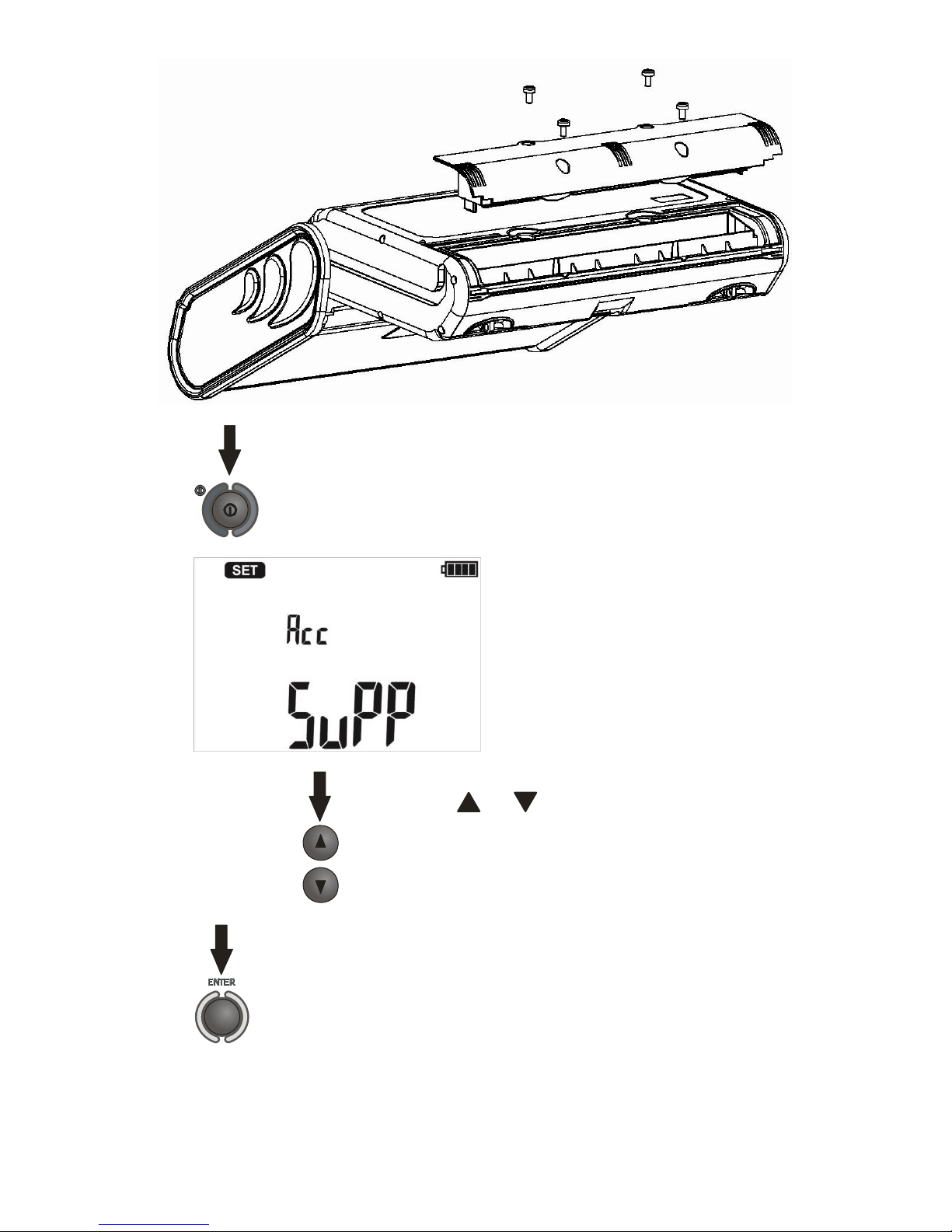
To replace the batteries:
remove all test leads from the sockets and turn the meter off,
remove the four screws of the battery compartment (in the lower part of the enclosure),
remove the compartment and take off the lid (use a tool),
remove and replace all batteries, observing the correct polarity when putting new batteries ("-" on
the spring). Reverse polarity will not damage the meter or the batteries, but the meter will not
work.
put on the lid, place the compartment and secure it with 4 screws.
Page 25
OPERATING MANUAL MRU-21 version 1.04
23
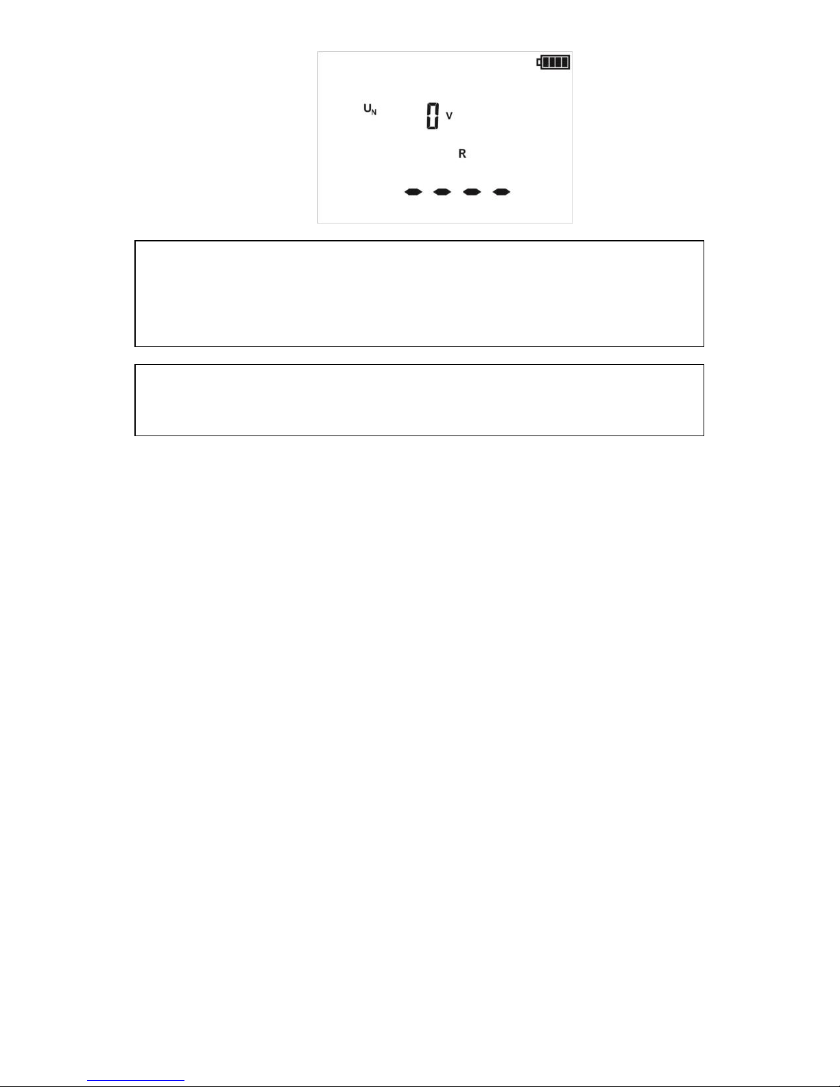
After replacement of batteries, the meter when turned on,
starts in the power supply selection mode.
Selected power supply:
rechargeable batteries:
Use the and symbols to select the power
supply: bAt (disposable batteries) or Acc
(rechargeable batteries).
Press ENTER to validate the choice
The meter goes to the measurement readiness mode.
Page 26
OPERATING MANUAL MRU-21 version 1.04
24
NOTE!
After replacing the batteries, always set the power supply type. The correct
charge indication depends on this setting (the discharge characteristics of
disposable and rechargeable batteries are different).
NOTE!
Have the meter serviced in case of battery leakage inside the compartment.
Batteries must be recharged in an external charger.
Page 27

OPERATING MANUAL MRU-21 version 1.04
25
6 Cleaning and maintenance
NOTE!
Apply only maintenance methods specified by the manufacturerin this manual.
The casing of the meter and its case may be cleaned with a soft, damp cloth using all-purpose
detergents. Do not use any solvents or cleaning agents which might scratch the casing (powders,
pastes, etc.).
Clean the probes with water and dry it. Before the probes are stored for a prolonged period of time
it is recommended to grease them with any machine lubricant.
The reels and test leads should be cleaned with water and detergents, and then dried.
The electronic system of the meter does not require maintenance.
7 Storage
The following recommendations must be observed to ensure proper storing of the device:
Disconnect all the test leads from the meter.
Clean the meter and all its accessories thoroughly.
Wind the long test leads onto the reels.
If the meter is to be stored for a prolonged period of time, the batteries must be removed from the
device.
in order to prevent total discharge of the rechargeable batteries during prolonged storage, charge
them from time to time.
8 Dismantling and utilization
Worn-out electric and electronic equipment should be collected selectively, i.e. it must not be
disposed with waste of another kind.
Worn-out electronic equipment should be sent to a collection point in accordance with regulations
related to Waste Electrical and Electronic Equipment.
Before the equipment is sent to a collection point, do not attempt to dismantle any elements.
Observe the local regulations concerning disposal of packages, worn-out batteries and
accumulators.
Page 28

OPERATING MANUAL MRU-21 version 1.04
26
9 Technical specifications
The specified accuracy relates to the meter terminals.
"m.v" means a standard measured value.
9.1 Basic data
Measurement of resistance to earth RE
Measurement method: technical, conforming with IEC 61557-5.
Measuring range acc. to IEC 61557-5: 0.50 ... 1.99kfor Un=50V
0.68 ... 1.99kfor Un=25V
Display range
Resolution
Basic uncertainty
0.00...9.99
0.01
(2% m.v. + 3 digits)
10.0...99.9
0.1
100...999
1
1.00...1.99k
0.01k
In the three-lead method, the meter displays the uncertainty caused by the probes resistance.
Such uncertainty can be also evaluated using the following diagram:
0,0010
0,0100
0,1000
1,0000
10,0000
100,0000
1 10 100 1000 10000 100000
Rezystancja elektrody napięciowej Rs[]
Błąd dodatkowy od rezystancji elektrod [%]
RH/RE=0,3
RH/RE=1
RH/RE=3
RH/RE=10
RH/RE=30
RH/RE=100
RH/RE=300
RH/RE=1000
RH/RE=3000
uziemienia aRezystancj
ądowejpr elektrody aRezystancj
E
H
R
R
Electrodes resistance and measurement uncertainty
Additional uncertainty caused by r
esistance of probes [%]
Voltage electrode resistance Rs[]
resistanceEarth
resistance electrodeCurrent
E
H
R
R
Page 29
OPERATING MANUAL MRU-21 version 1.04
27
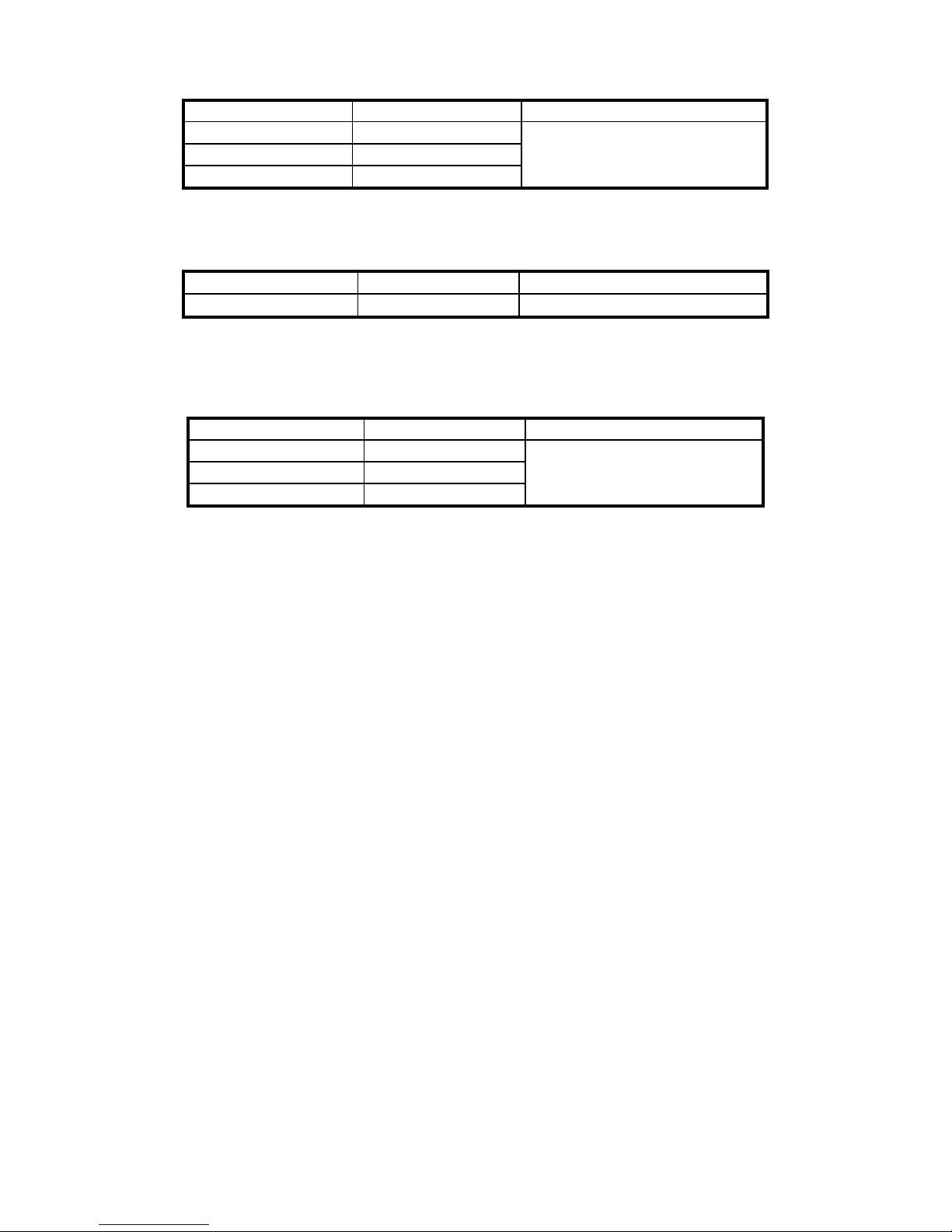
Measurement of resistance of auxiliary earth electrodes RH, R
S
Display range
Resolution
Measurement uncertainty
000...999
1
(5% (RS + RE + RH) + 3 digits)
1.00...9.99k
0.01k
10.0...50.0k
0.1k
Measurement of interference voltages
Internal resistance: about 100k
Display range
Resolution
Measurement uncertainty
0...100V
1V
(2% m.v. + 3 digits)
R
CONT
measurement
Measurement method: technical
Measuring range according to IEC 61557-4:
Display range
Resolution
Measurement uncertainty
0.00...9.99
0.01
(2% m.v. + 3 digits)
10.0...99.9
0.1
100...199
1
Note: Guaranteed are only the values with tolerances or limits. Values without tolerances are for
information only.
Other technical specification
a) type of insulation .................................................. double, PN-EN 61010-1 and IEC 61557 compliant
b) measurement category ..................................................................... IV 300V acc. to PN-EN 61010-1
c) degree of protection of enclosure acc. to PN-EN 60529 ............................................................. IP54
d) maximum interference voltage for the RE measurement .............................................................. 24V
e) maximum interference voltage for the R
CONT
measurement ........................................................... 3V
f) maximum measured interference voltage .................................................................................. 100V
g) RE test current frequency ....................................................................................................... 125 Hz
h) RE test voltage ................................ ................................................................ ................. 25V or 50V
i) RE test current ......................................................................................................................... 20mA
j) maximum resistance of test electrodes ..................................................................................... 50k
k) R
CONT
test current (with shorted terminals for U
BAT
6,0V) .................................................... 200mA
l) maximum voltage at open terminals for R
CONT
............................................................................. 13V
m) meter power supply .................................. R14 alkaline disposable or rechargeable batteries (4 pcs)
n) number of RE measurements ............................................ > 1000 (5, 2 measurements per minute)
o) dimensions ........................................................................................................... 288 x 223 x 75 mm
p) weight with batteries ....................................................................................................... about 1,4 kg
q) display .................................................................................................................. LCD with backlight
r) operating temperature ................................................................ ....................................... -10..+55C
s) reference temperature ........................................................................................................ +23 ± 2C
t) storage temperature ...................................................................................................... -20C..+70C
u) humidity ................................................................................................................................ 20...90%
v) reference humidity ................................................................................................................ 40...60%
w) time to AUTO-OFF ............................................................................................................. 5 minutes
x) the product meets the EMC requirements acc. to PN-EN 61326-1:2006 and PN-EN 61326-2-2:2006
y) quality standard ............................. development, design and manufacturing are ISO 9001 compliant
Page 30
OPERATING MANUAL MRU-21 version 1.04
28
9.2 Additional information
Data on additional uncertainties are useful mainly when the meter is used in non-standard
conditions and for metrological laboratories for the purpose of calibration.
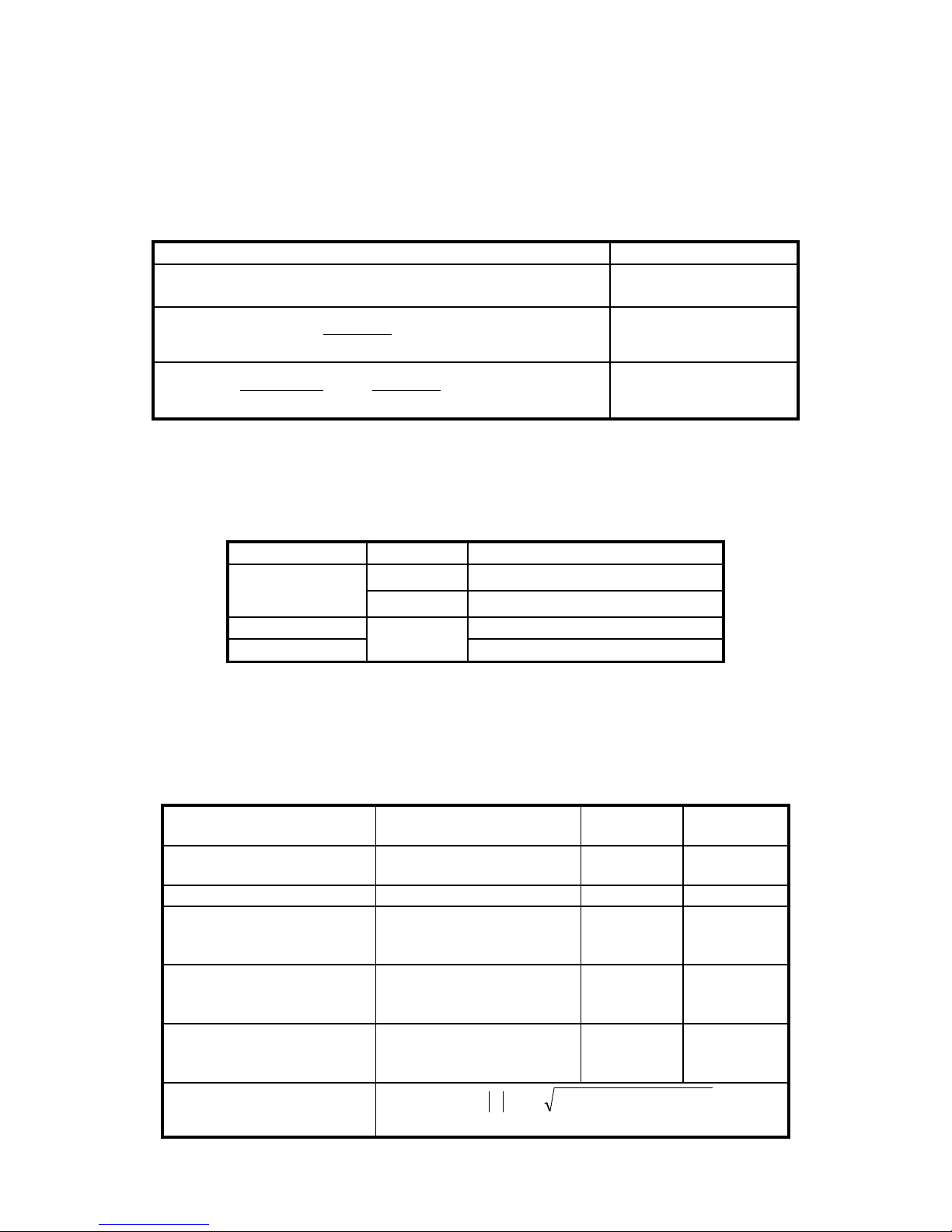
9.2.1 RE measurement
9.2.1.1 Additional uncertainty caused by resistance of auxiliary earth electrodes:
0%
RH and RS ≤ 100
7.5%
(RH ≥ 5k or RS ≥
5k) and RE ≥ 500
%105,1
004,0
5,7
28
H
E
H
dod
R
R
R
RS ≥ 5k and RE ≤
500
%105,1
004,0
150
100000
28
H
E
H
S
S
dod
R
R
R
R
R
remaining cases
The meter displays RE, RH and RS in [.This uncertainty is calculated by the meter and
displayed as ER.
9.2.1.2 Additional uncertainty caused by serial interference voltage
RE
Uwy
Additional uncertainty []
0.00…9.99
25V
(0.01RE + 0.012)Uz 0.007U
z
2
50V
(0.01RE + 0.012)Uz 0.003U
z
2
10.0…99.9
25V. 50V
(0.001RE + 0.05)Uz 0.001U
z
2
100…1.99k
(0.001RE + 0.5)Uz 0.001U
z
2
9.2.1.3 Additional uncertainty caused by ambient temperature
± 0.25 digit/°C for Uwy = 50V, ± 0.33 digit/°C for Uwy = 25V
9.2.1.4 Additional uncertainties according to IEC 61557-5
Working uncertainty or
influencing factors
Reference conditions or
operating range
Designation
Additional
uncertainty
Position
Reference position
±90°
E1
0
Power supply voltage
U
nom
÷ U
min
E2
0
Storage temperature
0 ÷ 35°C
E3
acc. to
formula
from 9.2.1.3
Serial interference voltage
3V
E4
acc. to
formula
from 9.2.1.2
Resistance of probes and
auxiliary earth electrodes
From 0 to 100RE, but ≤
50kΩ
E5
acc. to
formula
from 9.2.1.1
Working uncertainty
2
5
2
4
2
3
2
2
2
1
15,1 EEEEEAB
where A = measurement uncertainty
Page 31
OPERATING MANUAL MRU-21 version 1.04
29
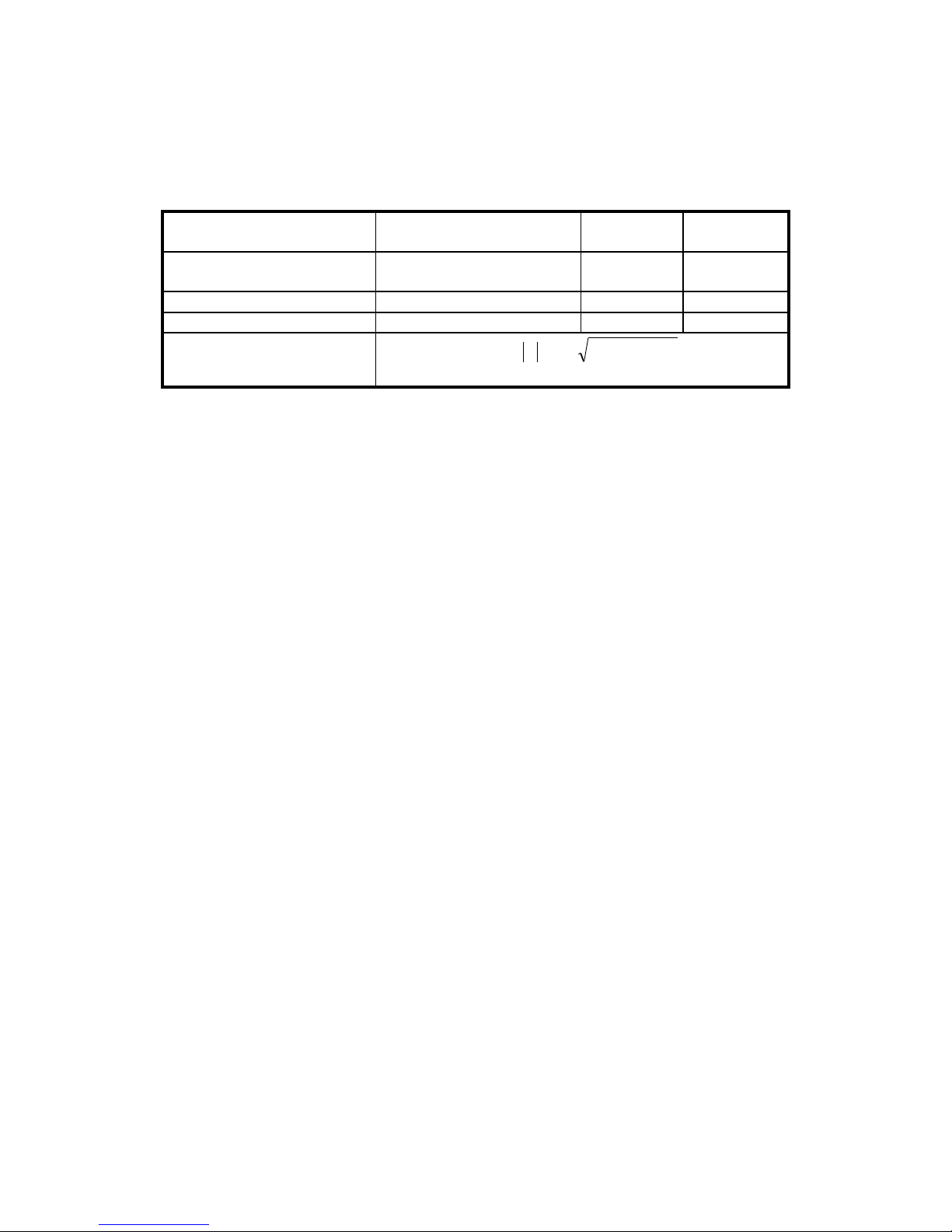
9.2.2 R
CONT
measurement
9.2.2.1 Additional uncertainty caused by ambient temperature
±0.15%/°C
9.2.2.2 Additional uncertainties according to IEC 61557-4
Working uncertainty or
influencing factors
Reference conditions or
operating range
Designation
Additional
uncertainty
Position
Reference position
±90°
E1
0
Power supply voltage
U
nom
÷ U
min
E2
0
Storage temperature
0 ÷ 35°C
E3
±0.15%/°C
Working uncertainty
2
3
2
2
2
1
15,1 EEEAB
where A = measurement uncertainty
Page 32
OPERATING MANUAL MRU-21 version 1.04
30
10 Equipment
10.1 Standard equipment
Standard set of equipment supplied by the manufacturer includes:
MRU-21 meter – WMPLMRU21,
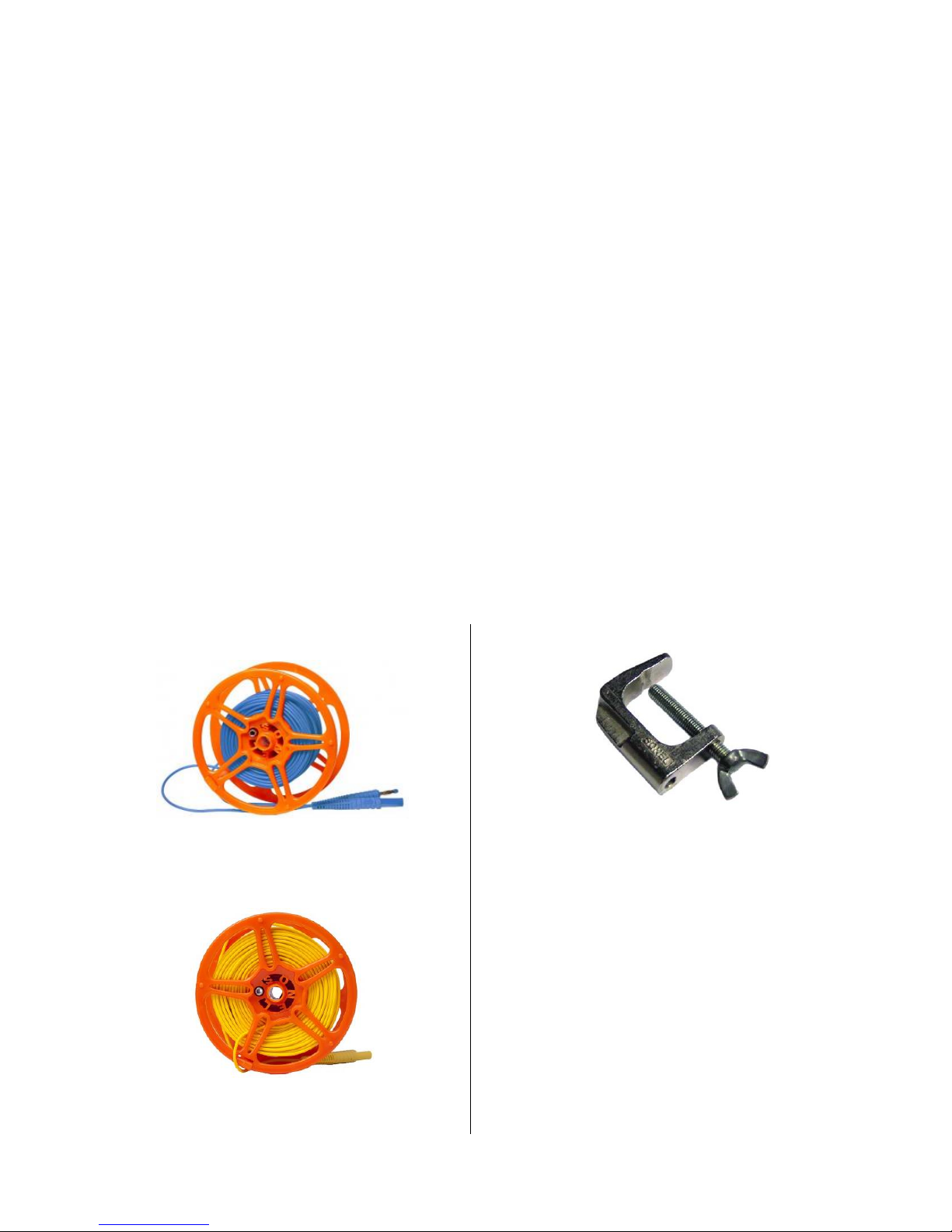
set of test leads:
30m lead on the reel (red) with banana plugs – WAPRZ030REBBSZ,
15m lead on the reel (blue) with banana plugs – WAPRZ015BUBBSZ,
2.2m lead (black) with banana plugs– WAPRZ2X2BLBB,
1.2m lead (blue) with banana plugs – WAPRZ1X2BUBB,
K01 crocodile clip, black – WAKROBL20K01,
K02 crocodile clip, blue – WAKROBU20K02,
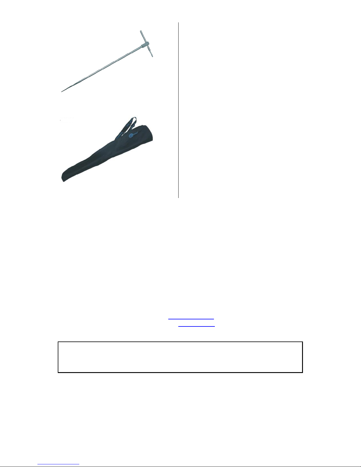
30cm test probe (2 pcs.) – WASONG30,
carrying case for the meter and accessories ,
harness (2 pcs, long and short) -WAPOZSZEKPL,
USB cable – WAPRZUSB,
LR14 batteries, (4 pcs),
SONEL CD,
operating manual,
warranty card,
calibration certificate
10.2 Optional accessories
Additionally, the following items that are not included in the scope of standard equipment can be
purchased from the manufacturer or the distributors:
WAPRZ025BUBBSZ
25m test lead (blue)
WAPRZ050YEBBSZ
50m test lead
WAZACIMA1
vise
LSWPLMRU21
calibration certificate
Page 33
OPERATING MANUAL MRU-21 version 1.04
31
WASONG80
80cm test probe
WAFUTL3
cover for the 80cm test probe
11 Manufacturer
The manufacturer of the device and provider of warranty and post-warranty service:
SONEL S.A.
ul. Wokulskiego 11
58-100 Świdnica
Poland
tel. +48 74 858 38 60
fax +48 74 858 38 09
E-mail: [email protected]
Web page: www.sonel.pl
NOTE
Service repairs must be performed solely by the manufacturer.
Page 34
OPERATING MANUAL MRU-21 version 1.04
32
Page 35
Page 36

 Loading...