

Page 1
Page 2
Page 3

OPERATING MANUAL
METER FOR ELECTRICAL
INSTALLATION PARAMETERS
MPI-530-IT
SONEL SA
ul. Wokulskiego 11
58-100 Świdnica
Version 1.06 07.03.2017
Page 4

MPI-530-IT meter is a modern, easy in use and safe measuring device. Please acquaint yourself with
this manual in order to avoid measuring errors and prevent possible problems in operation of the meter.
Page 5

OPERATING MANUAL MPI-530-IT version 1.06
3
CONTENTS
1 SAFETY .................................................................................................................... 6
2 MENU ........................................................................................................................ 7
2.1 WIRELESS TRANSMISSION ........................................................................................ 7
2.2 MEASUREMENT SETTINGS....................................................................................... 8
2.2.1 Earthing system, voltage and frequency ........................................................ 8
2.2.2 Main result of fault loop impedance measurement ........................................ 9
2.2.3 Measurement settings .................................................................................... 9
2.2.4 RCD AUTO measurement mode .................................................................. 10
2.2.5 Cell autoincrementing ................................................................................. 10
2.2.6 Resistivity measurement settings .................................................................. 11
2.2.7 Calibration of C-3 clamps ........................................................................... 11
2.2.8 Setting limits ................................................................................................ 12
2.3 METER SETTINGS ................................................................................................ . 12
2.3.1 LCD contrast ............................................................................................... 13
2.3.2 LCD Backlight ............................................................................................. 14
2.3.3 Automatic shut-off (Auto-OFF) ................................................................... 14
2.3.4 Date and time............................................................................................... 15
2.3.5 Key sounds ................................................................................................... 15
2.3.6 Factory (default) settings ............................................................................. 16
2.3.7 Software update ........................................................................................... 16
2.3.8 Wireless communication .............................................................................. 16
2.4 LANGUAGE SELECTION ......................................................................................... 17
2.5 INFORMATION ABOUT MANUFACTURER ................................................................. 17
3 MEASUREMENTS ................................................................................................ 18
3.1 DIAGNOSTICS PERFORMED BY THE METER - LIMITS ................................................ 18
3.2 MEASUREMENT OF ALTERNATING VOLTAGE AND FREQUENCY ................................ 18
3.3 CHECKING THE CORRECTNESS OF PE (PROTECTIVE EARTH) CONNECTIONS ............ 19
3.4 MEASUREMENT OF FAULT LOOP PARAMETERS ....................................................... 19
3.4.1 Measurement of fault loop parameters in the L-N and L-L circuits ............ 20
3.4.2 Measurement of fault loop parameters in the L-PE circuit ......................... 23
3.4.3 Measurement of fault loop impedance in L-PE circuit protected with a
residual current device (RCD) .................................................................... 25
3.4.4 Prospective short-circuit current ................................ ................................. 26
3.4.5 Measurements in IT networks ...................................................................... 27
3.5 MEASUREMENT OF RESISTANCE TO EARTH ............................................................ 28
3.5.1 Measurement of resistance to earth using 3p method.................................. 28
3.5.2 Measurement of resistance to earth using 4p method.................................. 32
3.5.3 Measurement of resistance to earth using 3p + clamps method .................. 36
3.5.4 Measurement of resistance to earth using double clamp method ................ 40
3.5.5 Measuring soil resistivity ............................................................................. 44
Page 6

OPERATING MANUAL MPI-530-IT version 1.06
4
3.6 MEASUREMENT OF RCD PARAMETERS .................................................................. 48
3.6.1 Measurement of RCD disconnection current ............................................... 48
3.6.2 Measurement of RCD disconnection time .................................................... 51
3.6.3 Automatic measurement of RCD parameters............................................... 52
3.6.4 Measurements in IT networks ...................................................................... 59
3.7 MEASUREMENT OF INSULATION RESISTANCE ......................................................... 60
3.7.1 Double-lead measurement ................................ ................................ ........... 61
3.7.2 Measurements by means of leads with UNI-Schuko outlet plug (WS-03 and
WS-04) ......................................................................................................... 64
3.7.3 Measurements with AutoISO-1000c adapter ............................................... 67
3.8 LOW-VOLTAGE MEASUREMENT OF RESISTANCE ..................................................... 70
3.8.1 Measurement of resistance of protective conductors and equipotential
bonding with ±200 mA current .................................................................... 70
3.8.2 Measurement of resistance .......................................................................... 73
3.8.3 Compensation of test leads resistance ......................................................... 74
3.9 CHECKING SEQUENCE OF PHASES ........................................................................ 75
3.10 CHECKING THE MOTOR ROTATION DIRECTION ....................................................... 77
3.11 LIGHT MEASUREMENTS......................................................................................... 78
3.12 RECORDER. MEASUREMENT AND RECORDING OF CURRENT, VOLTAGE, COSΦ, PF
FACTOR, HARMONICS AND THD........................................................................... 80
4 MEMORY OF MEASUREMENT RESULTS..................................................... 85
4.1 STRUCTURE OF THE MEMORY ............................................................................... 85
4.1.1 The appearance of main windows in the measurement recording mode ..... 86
4.2 STORING THE MEASUREMENT RESULTS DATA IN THE MEMORY ................................ 88
4.2.1 Entering the results without extending the memory structure ..................... 88
4.2.2 Extending the memory structure ................................ ................................ .. 89
4.3 BROWSING AND EDITING THE MEMORY .................................................................. 94
4.4 BROWSING THE RECORDER MEMORY. .................................................................... 96
4.5 DELETING MEMORY DATA ................................................................................... 100
5 DATA TRANSMISSION ..................................................................................... 101
5.1 SET OF ACCESSORIES TO CONNECT THE METER TO A PC ...................................... 101
5.2 DATA TRANSMISSION THROUGH USB PORT ......................................................... 101
5.3 CONNECTING TO BLUETOOTH MINI-KEYBOARD ................................................... 101
5.3.1 Manual connection .................................................................................... 101
5.3.2 Automatic connection ................................................................ ................ 103
5.4 DATA TRANSMISSION USING BLUETOOTH MODULE .............................................. 104
5.5 READ-OUT AND CHANGE OF PIN CODE FOR BLUETOOTH CONNECTIONS .............. 104
6 POWER SUPPLY OF THE METER ................................................................. 106
6.1 MONITORING THE POWER SUPPLY VOLTAGE ........................................................ 106
6.2 REPLACING BATTERIES (RECHARGEABLE BATTERIES) ........................................... 106
6.3 CHARGING RECHARGEABLE BATTERIES ............................................................... 107
Page 7

OPERATING MANUAL MPI-530-IT version 1.06
5
6.4 GENERAL PRINCIPLES FOR USING NI-MH RECHARGEABLE BATTERIES .................. 108
7 CLEANING AND MAINTENANCE .................................................................. 110
8 STORAGE ............................................................................................................ 110
9 DISMANTLING AND UTILISATION ................................ .............................. 110
10 TECHNICAL SPECIFICATIONS ..................................................................... 111
10.1 BASIC DATA ....................................................................................................... 111
10.2 ADDITIONAL DATA ................................ ................................ .............................. 122
10.2.1 Additional uncertainties according to IEC 61557-2 (R
ISO
) ........................ 122
10.2.2 Additional uncertainties according to IEC 61557-3 (Z) ............................ 122
10.2.3 Additional uncertainties according to IEC 61557-4 (R ±200 mA) ............ 122
10.2.4 Additional uncertainties of earth resistance measurement (RE) ................ 122
10.2.5 Additional uncertainties according to IEC 61557-6 (RCD) ...................... 123
10.3 LIST OF REFERENCE STANDARDS ......................................................................... 124
11 EQUIPMENT ....................................................................................................... 124
11.1 STANDARD EQUIPMENT ...................................................................................... 124
11.2 OPTIONAL ACCESSORIES ..................................................................................... 124
11.2.1 Clamps C-3 ................................................................................................ 127
11.2.2 Clamps C-6 ................................................................................................ 129
11.2.3 Clamps F-1, F-2, F-3 ................................................................................. 130
11.2.4 Clamps N-1 ................................................................................................ 131
12 POSITIONS OF THE METER’S COVER ........................................................ 132
13 MANUFACTURER ............................................................................................. 132
Page 8

OPERATING MANUAL MPI-530-IT version 1.06
6
1 Safety
MPI-530-IT meter is designed for performing check tests of protection against electric shock in
AC mains systems. The meter is used for making measurements and providing results to determine
safety of electrical installations. Therefore, in order to provide conditions for correct operation and
accuracy of obtained results, the following recommendations must be observed:
Before you proceed to operate the meter, acquaint yourself thoroughly with the present manual
and observe the safety regulations and specifications provided by the producer.
Any application that differs from those specified in the present manual may result in a damage to
the device and constitute a source of danger for the user.
MPI-530-IT meters must be operated only by appropriately qualified personnel with relevant certif-
icates authorising the personnel to perform works on electric systems. Operating the meter by
unauthorised personnel may result in damage to the device and constitute a source of danger for
the user.
Using this manual does not exclude the need to comply with occupational health and safety regu-
lations and with other relevant fire regulations required during the performance of a particular type
of work. Before starting the work with the device in special environments, e.g. potentially firerisk/explosive environment, it is necessary to consult it with the person responsible for health and
safety.
It is unacceptable to operate:
a damaged meter which is completely or partially out of order,
a meter with damaged insulation,
a meter stored for an excessive period of time in disadvantageous conditions (e.g. excessive
humidity). If the meter has been transferred from a cool to a warm environment with a high
level of relative humidity, do not start measurements until the meter is warmed up to the ambient temperature (approximately 30 minutes).
Displayed BAT! symbol indicates insufficient voltage of power supply and the need to charge the
accumulator or replace batteries. All measurements except voltage measurements for Z and
RCD functions are blocked.
Battery spill and damage to the meter may occur if discharged batteries are left in the meter.
Before measurements may commence, make sure the leads are connected to the appropriate
measurement sockets.
Do not operate a meter with an open or incorrectly closed battery (accumulator) compartment or
power it from other sources than those specified in the present manual.
R
ISO
meter inputs are electronically protected against overloads (caused by e.g. connecting the
meter to a live circuit) up to 440V rms for 60 seconds.
Repairs may be performed only by an authorised service point.
ATTENTION!
Only standard and additional accessories for a given device should be used, as listed
in the "Equipment" section. Using other accessories may cause damage to measuring
terminals, introduce additional measurement uncertainty and create a risk for the user.
Note:
Due to continuous development of the meter’s software, the actual appearance of the
display, in case of some of the functions, may slightly differ from the display presented
in this operating manual.
Page 9
OPERATING MANUAL MPI-530-IT version 1.06
7
Note:
An attempt to install drivers in 64-bit Windows 8 may result in displaying "Installation failed" message.
Cause: Windows 8 by default blocks drivers without a digital signature.
Solution: Disable the driver signature enforcement in Windows.
2 Menu
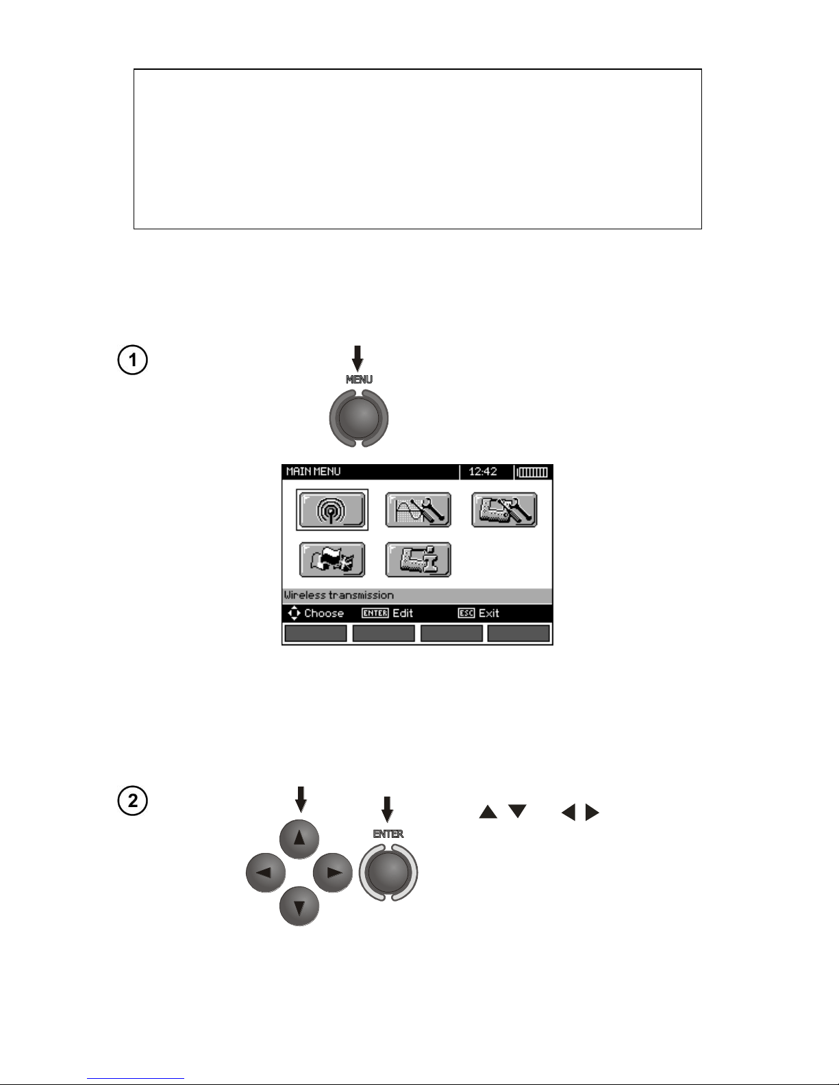
The Menu is accessible in each position of the rotary switch.
Press MENU push-button.
The main menu contains the following items:
Wireless transmission
Measurement Settings
Meter Settings
Language selection
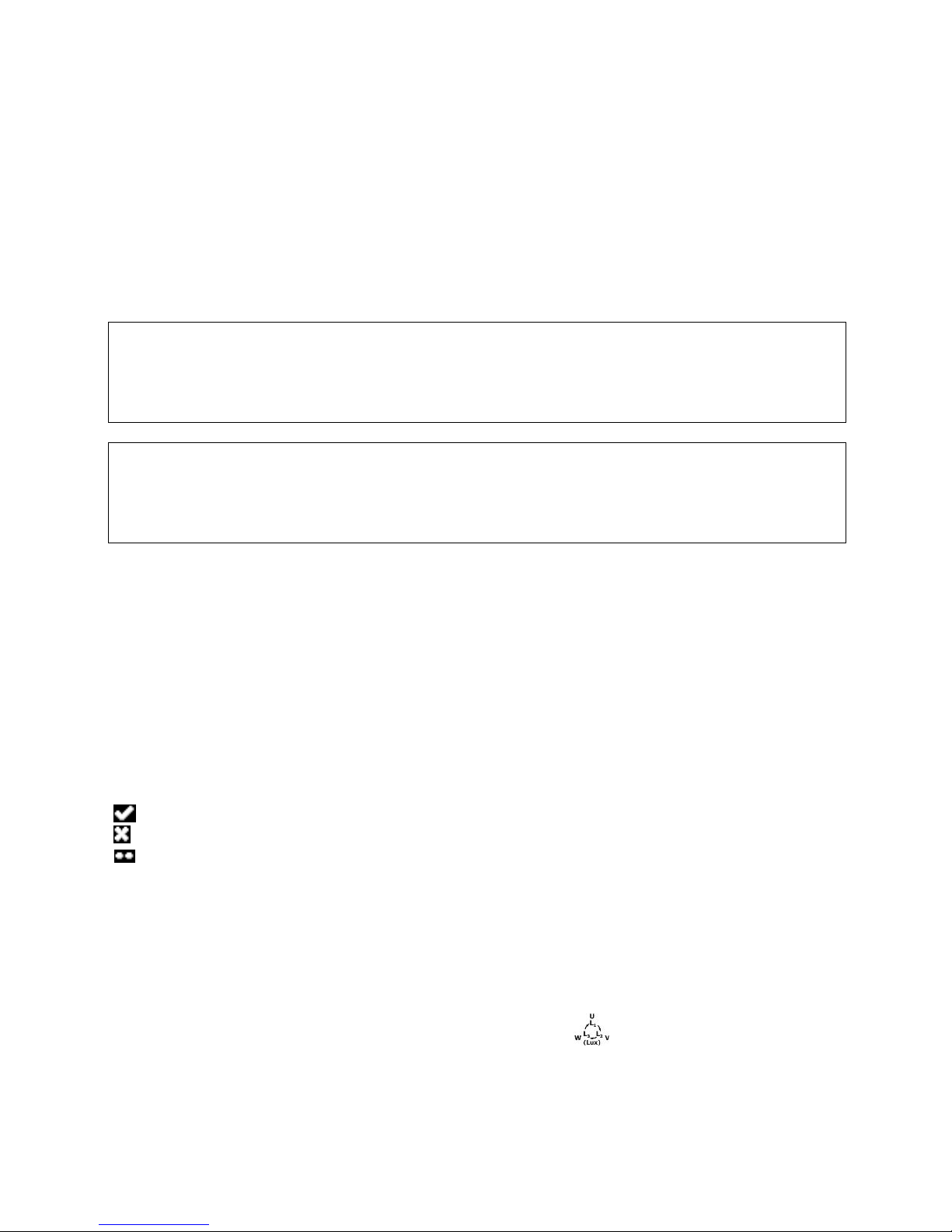
Information about manufacturer
Use , and , to select desired
position. Enter a selected option by
pressing ENTER.
2.1 Wireless transmission
See section 5.3.
Page 10
OPERATING MANUAL MPI-530-IT version 1.06
8
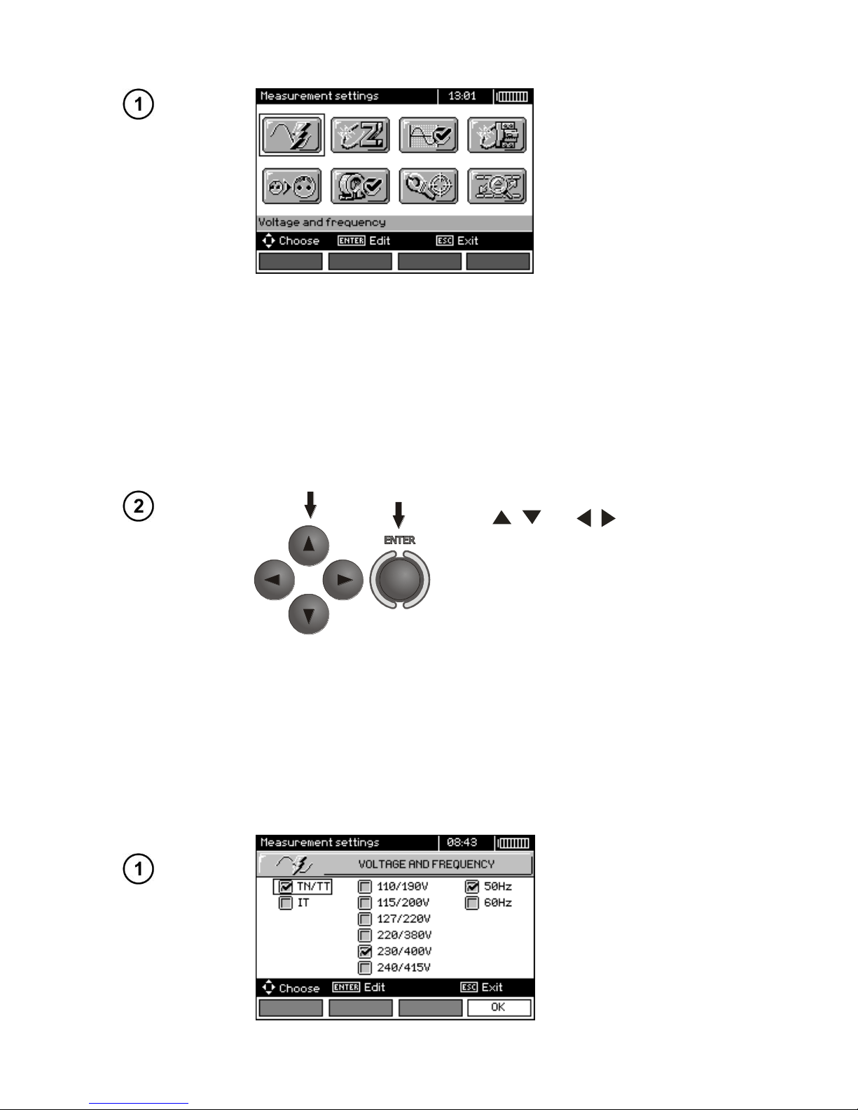
2.2 Measurement Settings
The option of Measurement settings consists of:
Voltage and frequency
The main result for fault loop
Assessing fault loop measurement
Measurement settings
RCD AUTO measurement mode
Cell autoincrementing
Resistivity measurement settings
Calibration of C-3 clamps
Setting limits
Use , and , to select desired
position. Enter a selected option by
pressing ENTER.
2.2.1 Earthing system, voltage and frequency
Before first measurements, select earthing system used in the area where measurements are
performed. Then select the mains rated voltage Un (110/190 V, 115/200 V, 127/220 V, 220/380 V,
230/400 V or 240/415 V). This voltage value is used for calculating the values of prospective shortcircuit current.
Determination of network frequency, that is the source of potential interferences, is necessary in
order to select a proper measuring signal frequency in resistance-to-earth measurements. Only the
measurement conducted with a properly selected frequency of measuring signal will ensure optimum
filtration of interferences. The meter is designed for filtration of interferences generated by 50 Hz and
60 Hz networks.
Page 11
OPERATING MANUAL MPI-530-IT version 1.06
9
Use , and , to select the
voltage and frequency. Press ENTER to
select the desired item. Press F4 (OK) to
approve the selection.
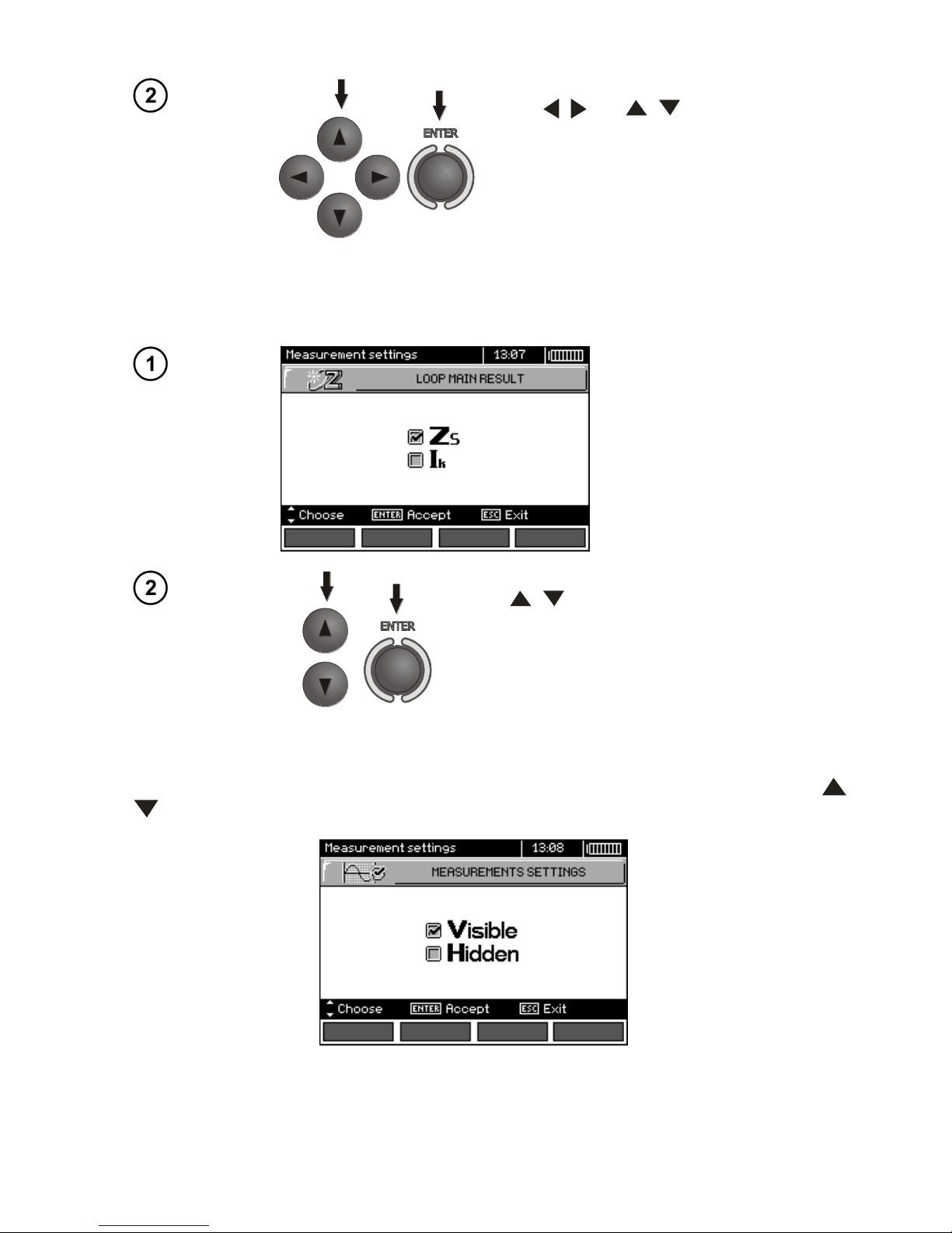
2.2.2 Main result of fault loop impedance measurement
Use , to select the main result as ZS
impedance or as Ik - prospective short-circuit
current and press ENTER to confirm your selection.
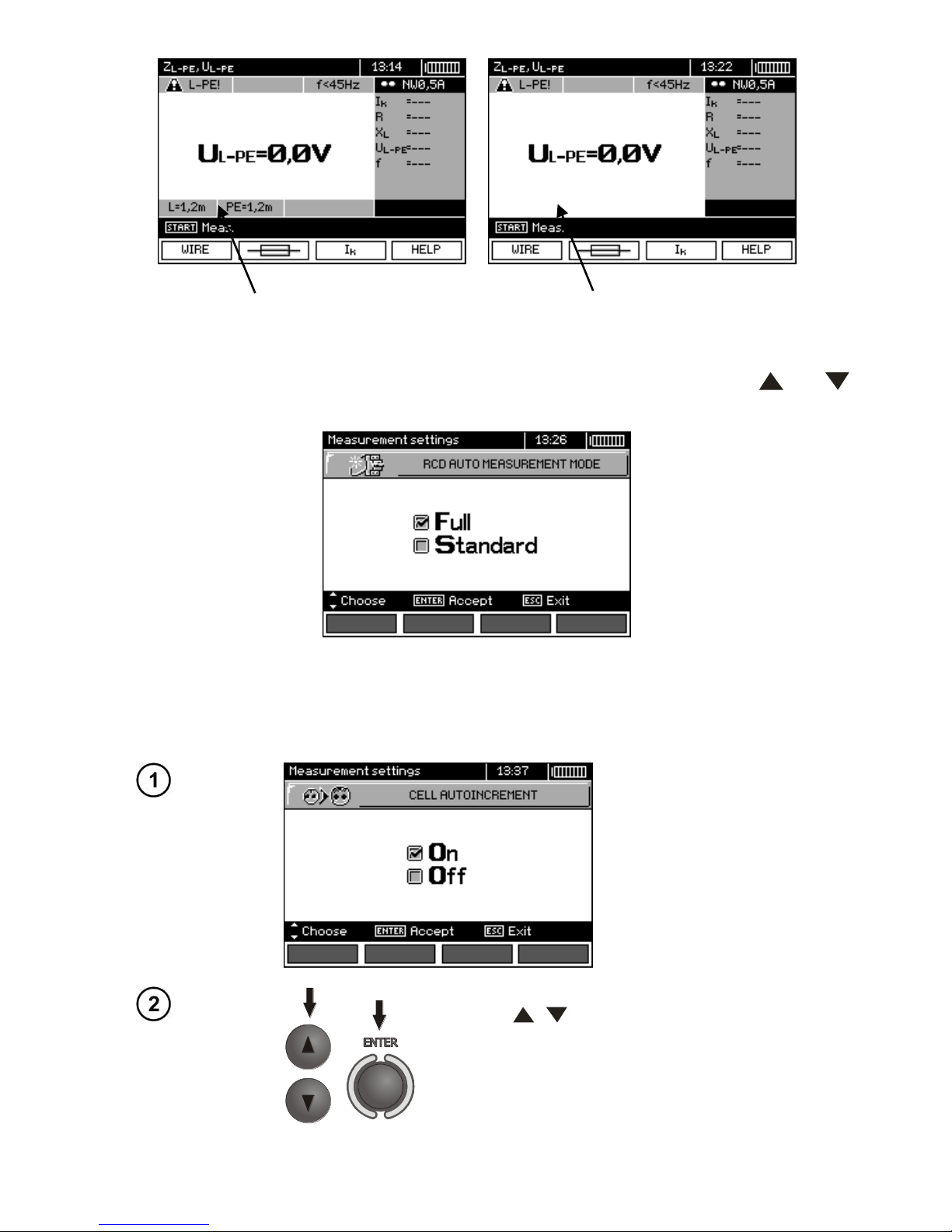
2.2.3 Measurement settings
The setting enables activation/deactivation of the field displaying measurement settings. Use
and to display or hide the field with measurement settings and press ENTER.
Page 12
OPERATING MANUAL MPI-530-IT version 1.06
10
Displayed measurement settings Hidden measurement settings
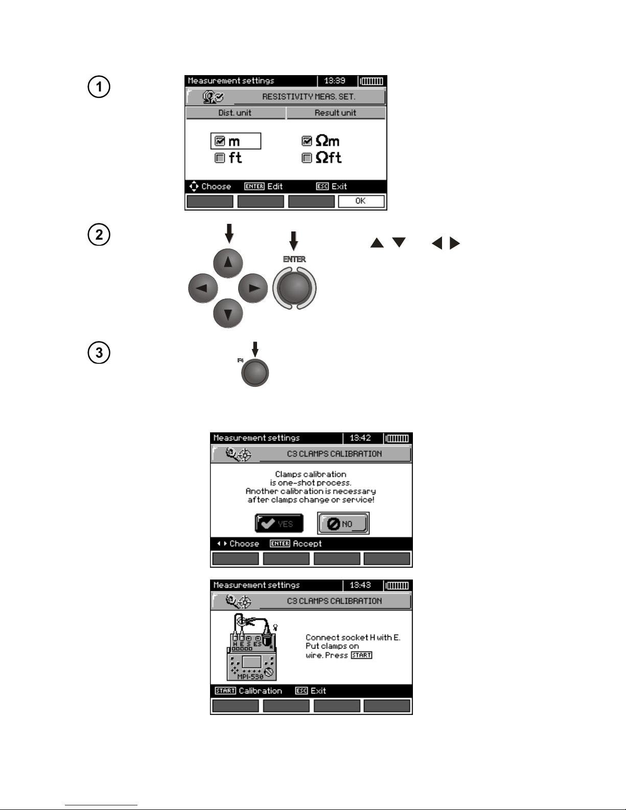
2.2.4 RCD AUTO measurement mode
This setting enables user to select desired measurement mode of RCD AUTO. Use and
to select desired mode and press ENTER.
In the standard mode, measurements are performed for a selected current waveform, in the full
mode for all current waveforms of a given type of RCD (AC, A, B).
2.2.5 Cell autoincrementing
Use , to select automatic or manual incrementing of field number after entering it to
the memory (automatic incrementing is deactivated), press ENTER to approve the selection.
Page 13
OPERATING MANUAL MPI-530-IT version 1.06
11
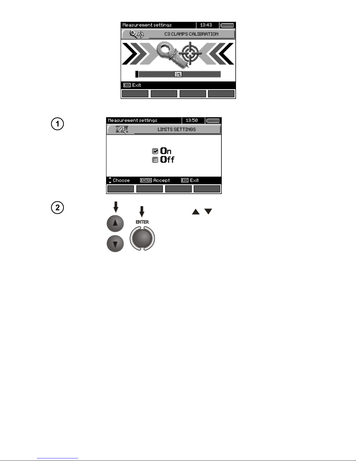
2.2.6 Resistivity measurement settings
Use , and , to select
length unit and result unit, press
ENTER to mark your choice.
Press F4 to approve the selection.
2.2.7 Calibration of C-3 clamps
Page 14
OPERATING MANUAL MPI-530-IT version 1.06
12
2.2.8 Setting limits
Use , to switch on/off the function of
setting limits, press ENTER to confirm.
Note:
- Detailed description of the diagnostics functions (including application of limit values) carried by the
meter is described in chapter 3.1.
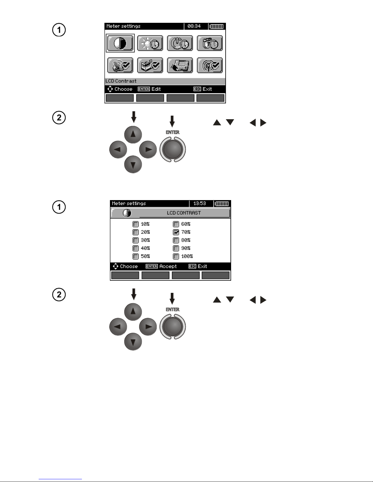
2.3 Meter Settings
The option of Meter Settings consists of:
LCD contrast
LCD Backlight
Automatic shut-off
Date and time
Key sounds
Factory (default) settings
Updating the meter
Wireless communication
Page 15
OPERATING MANUAL MPI-530-IT version 1.06
13
Use , and , to select desired
position and press ENTER to edit selected option.
2.3.1 LCD contrast
Use , and , to adjust contrast; press ENTER to confirm.
Page 16
OPERATING MANUAL MPI-530-IT version 1.06
14
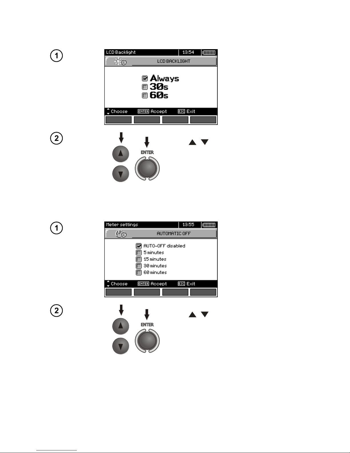
2.3.2 LCD Backlight
This setting defines the time for automatic backlight shut-off: 30 s, 60 s, or disabled.
Use , to set the time for LCD Backlight
shut-off and press ENTER to confirm.
2.3.3 Automatic shut-off (Auto-OFF)
The setting defines the shut-off time of idle meter.
Use , to set Auto-OFF time and press
ENTER to confirm.
Page 17
OPERATING MANUAL MPI-530-IT version 1.06
15
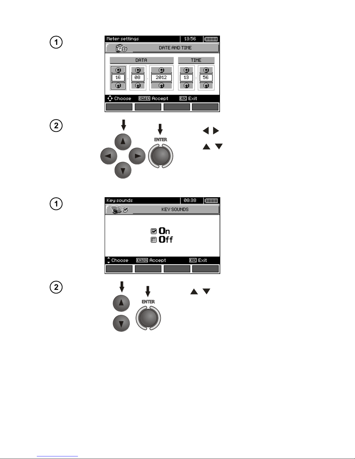
2.3.4 Date and time
Use , to select the value to be
changed (day, month, year, hour, minute)
Use , to set the desired value.
When required settings are made, press
ENTER.
2.3.5 Key sounds
Use , buttons to switch-off sound signals assigned to push buttons.
Note:
- Warning sound signals: U>440V, U>50V, Rbeep, PE!, cannot be switched-off, they remain constantly active.
Page 18
OPERATING MANUAL MPI-530-IT version 1.06
16
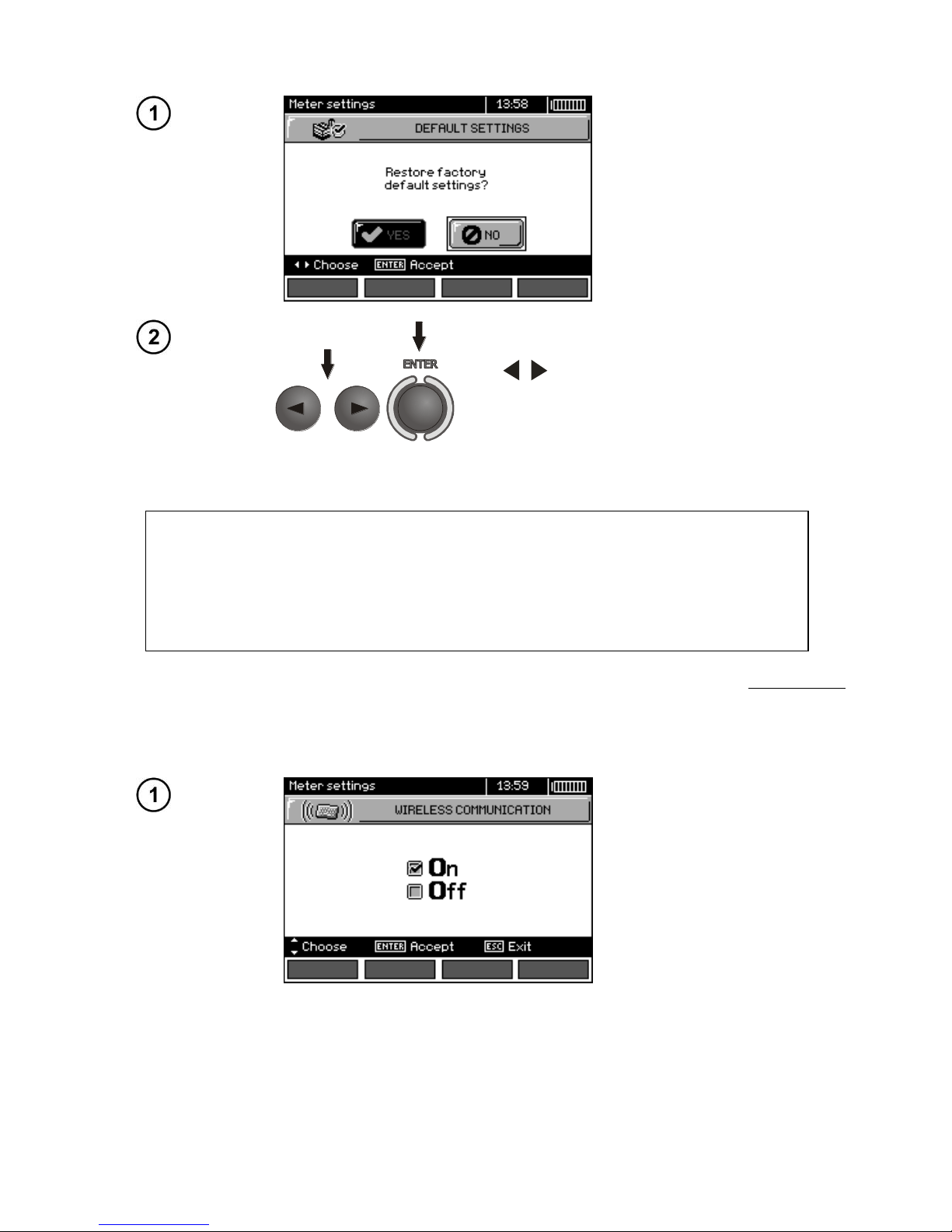
2.3.6 Factory (default) settings
In order to return to factory (default), use
, to select YES and press ENTER.
2.3.7 Software update
ATTENTION!
A new battery pack should be installed or rechargeable batteries should be recharged before programming.
During programming the meter must not be switched off as well as the transmission cable must not be disconnected.
Before updating software, download the software from the manufacturer’s website (www.sonel.pl)
and install it on your PC, then connect the meter to PC.
Select Software upgrade in the MENU and follow the instructions displayed by the program.
2.3.8 Wireless communication
Page 19
OPERATING MANUAL MPI-530-IT version 1.06
17
Use , to select the wireless communication ON/OF and press ENTER to confirm.
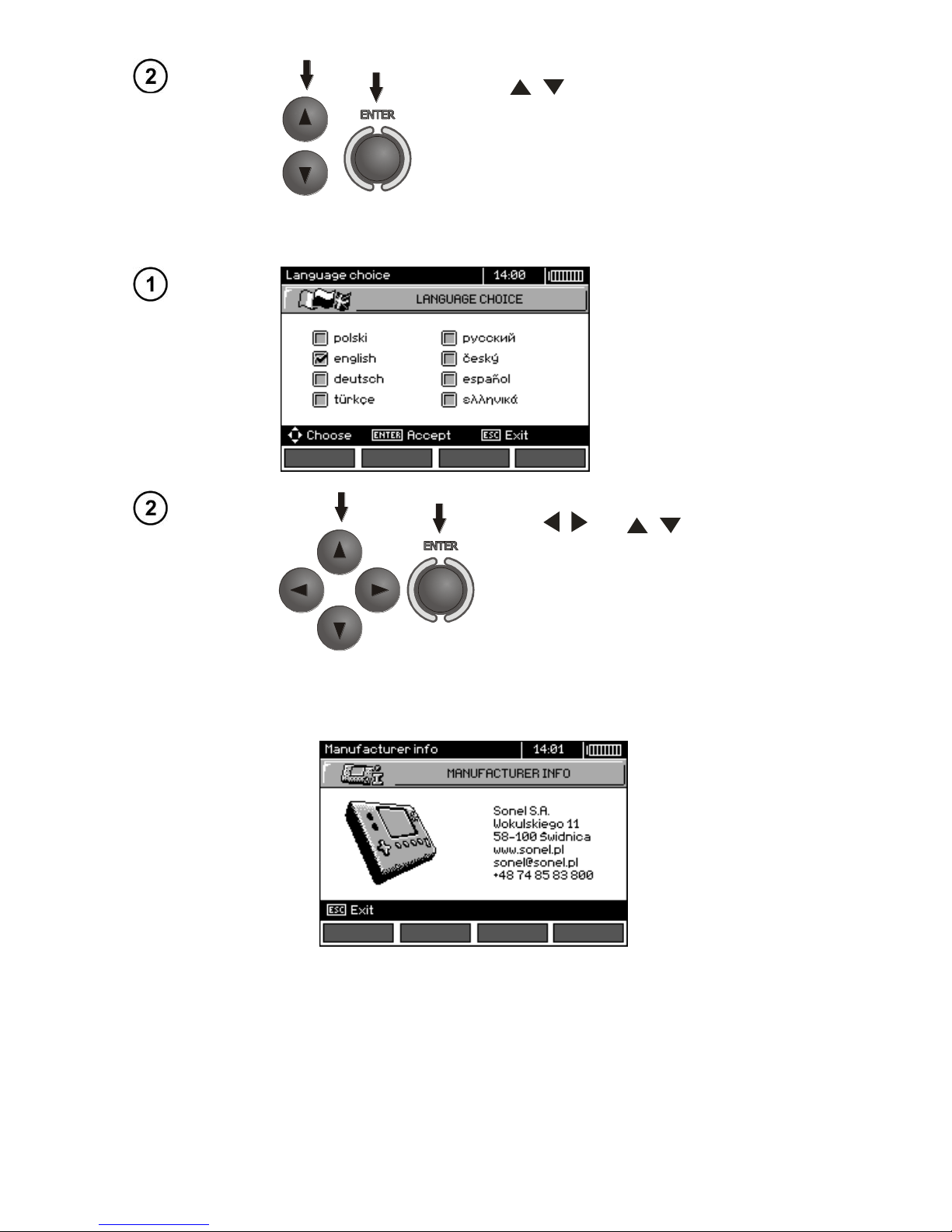
2.4 Language selection
Use , and , to select desired
language and press ENTER.
2.5 Information about manufacturer
Page 20
OPERATING MANUAL MPI-530-IT version 1.06
18
3 Measurements
Note:
- A progress bar is displayed during long measurements.
- The content of this chapter should be thoroughly familiarized with since it describes the meter circuits, the methods of measurements and basic principles concerning interpretation of measurement
results.
- Result of the latest measurement is remembered by the meter until a next measurement is started
or measurement settings are changed or the measuring function is changed by means of the rotary
switch or the meter is switched off. It is displayed for 20 s. Then it may be recalled by pressing
ENTER.
WARNING:
During measurements (fault loop, RCD), do not touch earthed and accessible parts of the
tested electrical installation.
WARNING:
During a measurement, switching of the range switch is forbidden because it may damage
the meter and pose a threat to the user.
3.1 Diagnostics performed by the meter - limits
The meter is able to assess whether the measurement result is within acceptable limits for the
selected safety device or the limit value. The user may set a limit, i.e. maximum or minimum value,
which should not be exceeded by the result. It is possible for all measurement functions except RCD
measurements for which limits are set and permanently active and for the recorder function. For
measurements of insulation resistance and light, the set limit is the minimum value, whereas for the
following measurements: fault loop impedance, earth resistance, resistance of protective conductors
and equipotential bonding - it is the maximum value.
The limits are activated globally in the main menu (Section 2.2.9). When the function of setting
limits is activated, the display, in its upper right corner, shows the symbols with the following meaning:
- : the result is correct, it is within the set limits,
- : the result is incorrect, it is outside the set limits,
- : the correctness of the result cannot be assessed: this symbol is displayed, when for example
the result is not available (e.g. measurement in progress, or no measurement has been performed)
The method for setting limits is described in the chapters describing the measurement data. It
should be noted that for the fault loop the limit is determined indirectly by selecting a suitable overcurrent protection for which standard limits are assigned.
3.2 Measurement of alternating voltage and frequency
The meter measures and displays alternating voltage and frequency of the network in all measur-
ing functions except RE, R
X
, R±200mA, R
ISO
-conductor. For function (phase sequence) and
R
ISO
voltage is displayed without frequency. This voltage is measured for the frequencies within the
range of 45...65 Hz as True RMS. If the measured frequency is outside the specified range, the following message is displayed instead of the frequency value: f<45Hz or f>65Hz. Voltage is displayed
Page 21
OPERATING MANUAL MPI-530-IT version 1.06
19
as the main result only for U
L-N,L-L
, Z
L-N,L-L
, U
L-PE ZL-PE
and LOGGER. The test leads should be con-
nected as for a given measuring function.
3.3 Checking the correctness of PE (protective earth) connections
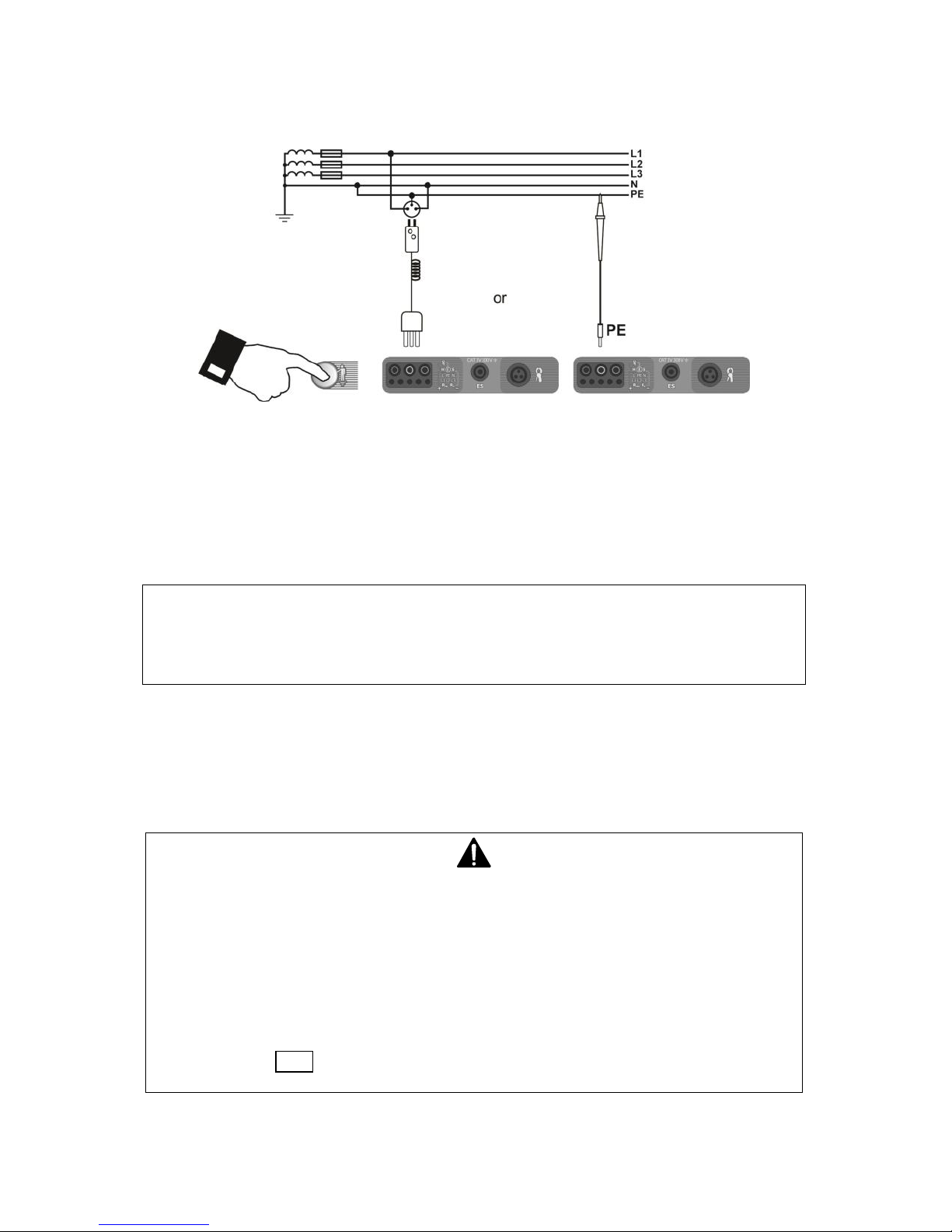
After connecting the meter according to the drawing, touch the contact electrode with a finger and
wait for about 1 second. When voltage is found on PE the meter displays PE! symbol (error in the installation; PE connected to the phase conductor) and generates a continuous beep. This option is
available for all measuring functions that apply to residual current devices (RCD) and fault loop.
Note:
WARNING:
When phase voltage is detected on PE lead, measurements must be immediately
stopped and a fault in the installation must be removed.
- The person making a measurement must ensure that he/she is standing on a non-insulated floor
during the measurement; otherwise the result of the measurement may be incorrect.
- The threshold value, which triggers the signal of exceeded allowable voltage on PE conduit, is approximately 50 V.
3.4 Measurement of fault loop parameters
If there are residual current devices in the network tested, they should be bypassed by bridging for the period of impedance measurement. However, it
should be remembered that the tested circuit is modified in this way and the obtained results may slightly differ from the actual results.
After completing measurements, always remove modifications introduced to the
tested system for the period of measurements and check the operation of the residual current switch.
The above remark does not apply to measurements of fault loop impedance with
the use of Z
L-PE
RCD function.
Page 22
OPERATING MANUAL MPI-530-IT version 1.06
20
Measurements of fault loop impedance performed downstream of inverters are
ineffective and their results are unreliable. This is due to the instability of internal
impedance in inverter circuits during its operation. The measurements of fault
loop impedance should not be performed directly downstream of inverters.
3.4.1 Measurement of fault loop parameters in the L-N and L-L circuits
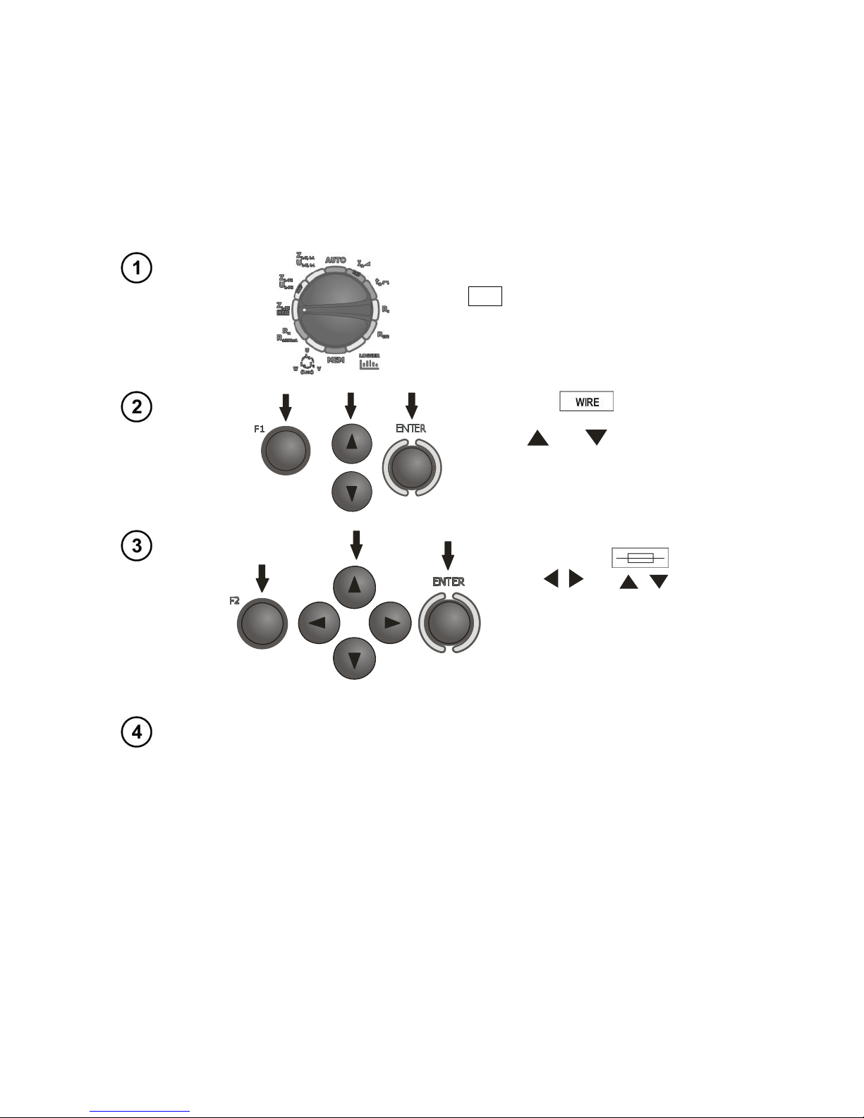
Settings
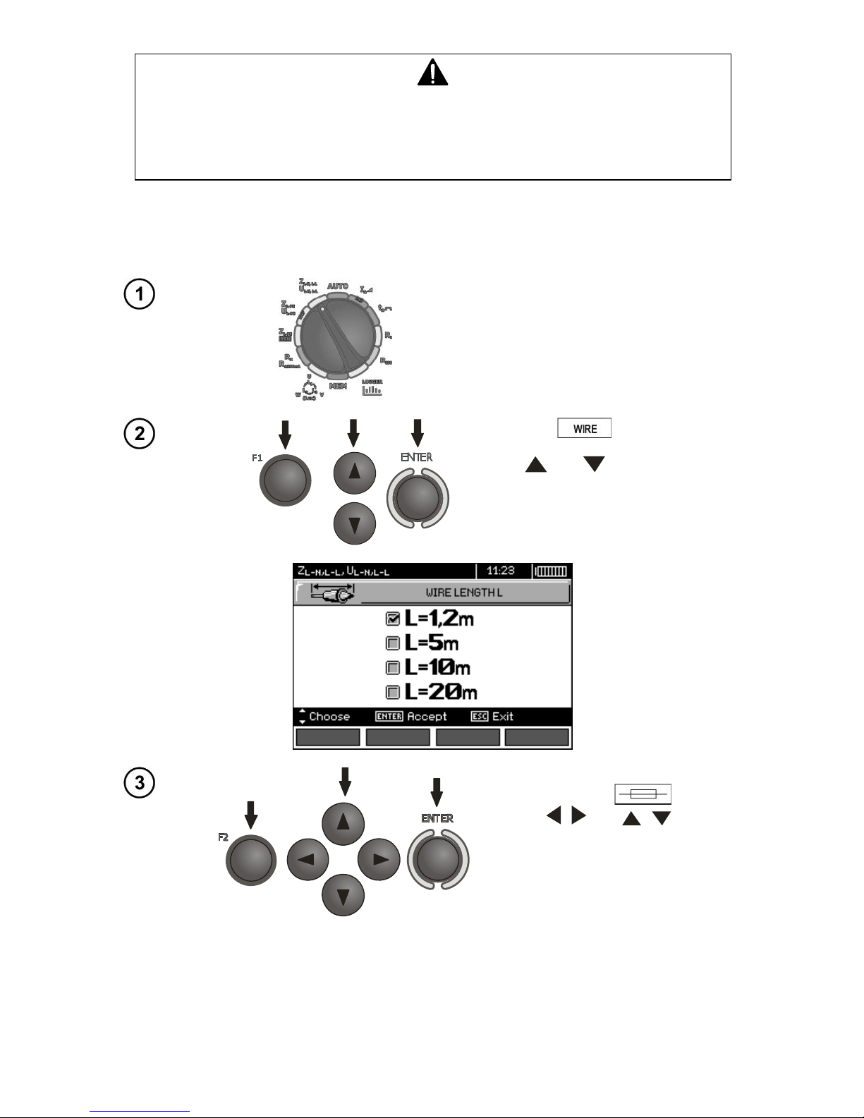
Set the rotary switch of function selection at
Z
L-N,L-L/UL-N,L-L
position.
Press F1 push-button if L
lead length needs to be selected.
Use and to select the lead
length and press ENTER.
In order to set the security parameters press F2 .
Use , and , to set the
security parameters and press
ENTER.
Page 23
OPERATING MANUAL MPI-530-IT version 1.06
21
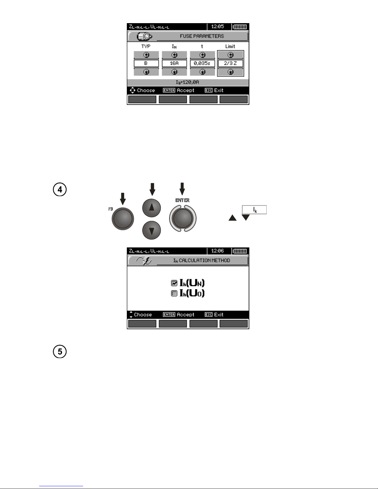
The symbols displayed on the above screen have the following meaning:
TYPE - type of security
IN - rated security current
t -response time
Limit - a limit resulting from a standard (when selecting 2/3Z Ia it is increased by ½Ia, when selecting
---- Ia it is as stated in the tables of the standard - without correction)
Ia - current ensuring automatic triggering of a protective device in a required time, determined auto-
matically basing on pre-set parameters of security settings
In order to select the voltage for calculating the prospective short circuit
current Ik - nominal or measured -
press F3 .
Use , to select desired voltage
and press ENTER.
Measurement
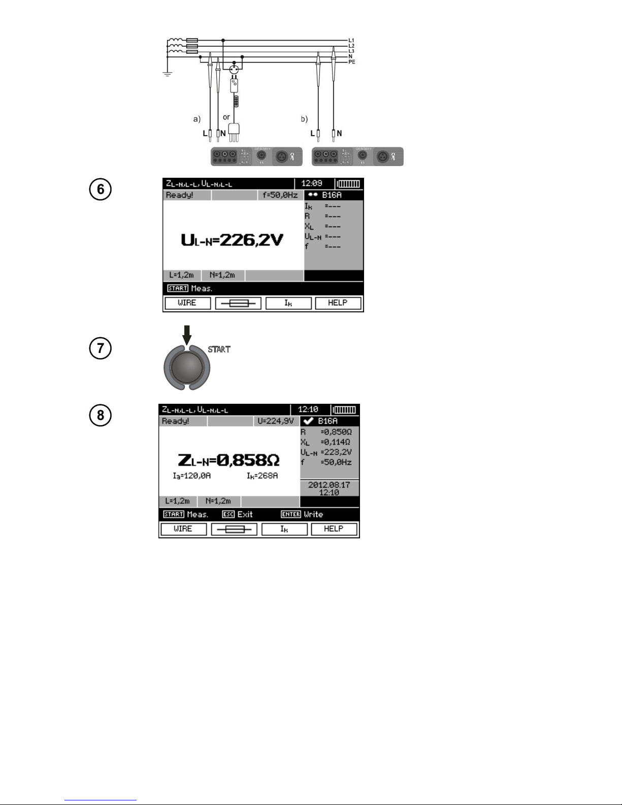
Connect test leads according to the drawing
a) for measurement in L-N circuit or
b) for measurement in L-L circuit
Page 24
OPERATING MANUAL MPI-530-IT version 1.06
22
The meter is ready for measurement.
Make measurement by pressing START push-button.
Read out the result:
Z
L-N
- the main result
Ia - current ensuring automatic
triggering of a selected protective
device in a required time
Ik - prospective short-circuit current
R, XL, U
L-N
, f - additional results.
The result is displayed on the screen for 20 s.
The result can be recalled by pressing ENTER push-button.
Note:
- The result may be entered into the memory (see sec. 4.2).
- When many measurements are made in short time intervals, the meter may emit a large amount of
heat. As a result of this, the housing of the device may become hot. This is normal and the meter is
equipped with the protection against excessive temperature.
- Minimum interval between successive measurements is 5 seconds. This minimum interval requirement is controlled by the meter. The next measurement may be performed only when READY! message appears on the screen. Until the message is displayed - the meter prevents any measurements.
Page 25
OPERATING MANUAL MPI-530-IT version 1.06
23
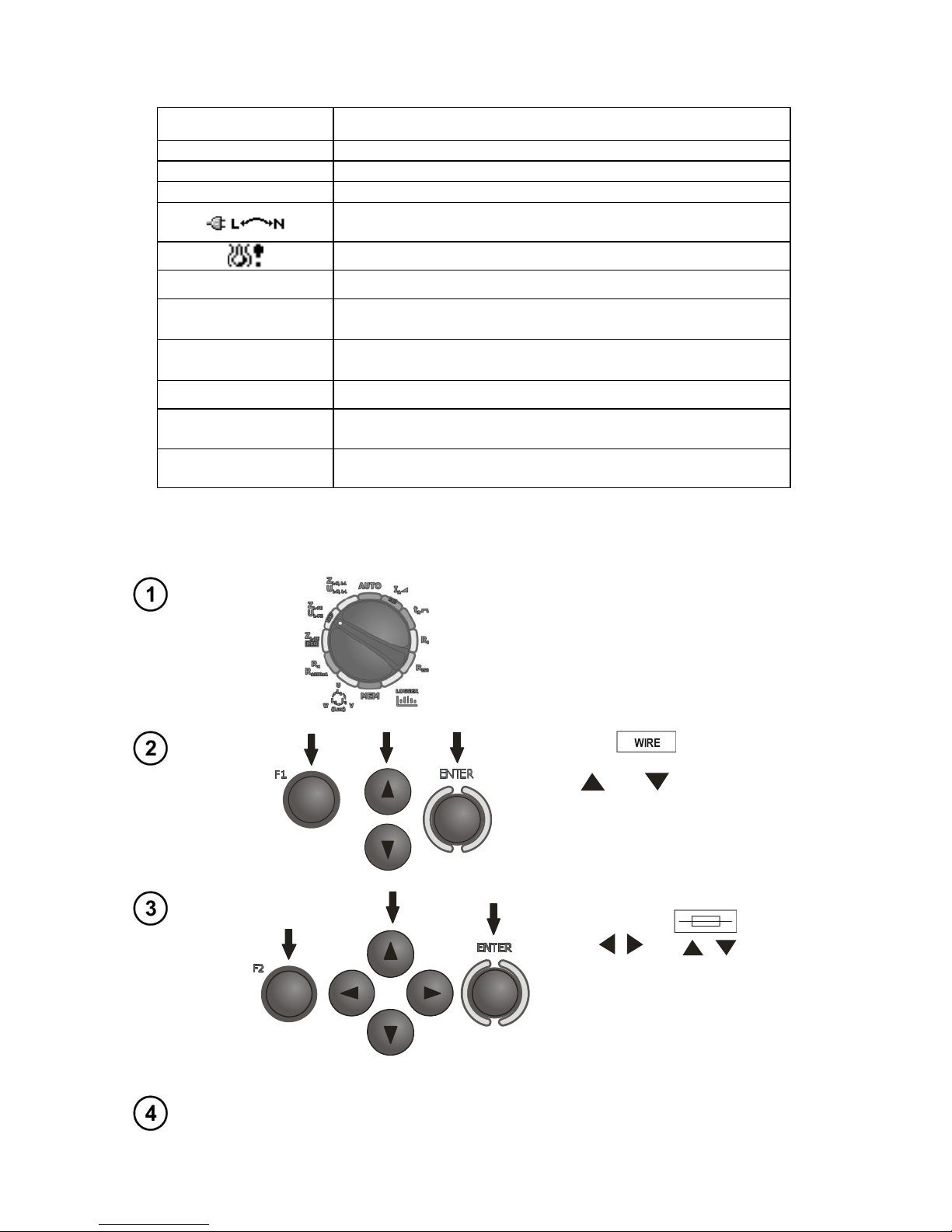
Additional information displayed by the meter
READY!
The meter is ready for measurement.
L-N!
U
L-N
voltage is incorrect for making a measurement.
L-PE!
U
L-PE
voltage is incorrect for making a measurement.
N-PE!
U
N-PE
voltage exceeds allowable value of 50V.
Phase connected to N terminal instead of L terminal (for
example, exchange of L and N in the mains socket).
Temperature exceeded.
f!
Network frequency is outside the range of 45 Hz ...65 Hz.
Error during mea-
surement
Correct result cannot be displayed.
Loop circuit mal-
function!
The meter should be serviced.
No U
L-N
!
Lack of U
L-N
voltage before the main measurement.
U>500 V! and con-
tinuous audio signal
Before measurement, voltage at test terminals exceeds
500 V.
LIMIT
Too low value of the prospective short circuit current Ik for
the pre-set security and time of its triggering.
3.4.2 Measurement of fault loop parameters in the L-PE circuit
Settings
Set the rotary switch of function selection at
Z
L-PE/UL-PE
position.
Press F1 push-button if L
lead length needs to be selected.
Use and to select the lead
length and press ENTER.
In order to set the security parameters press F2 .
Use , and , to set the
security parameters and press
ENTER.
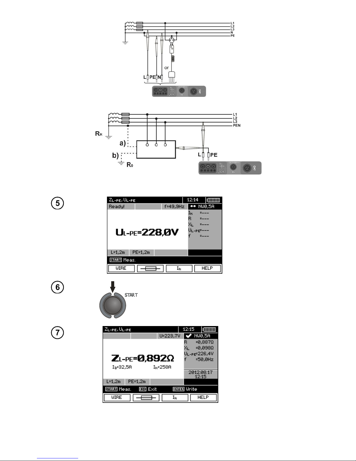
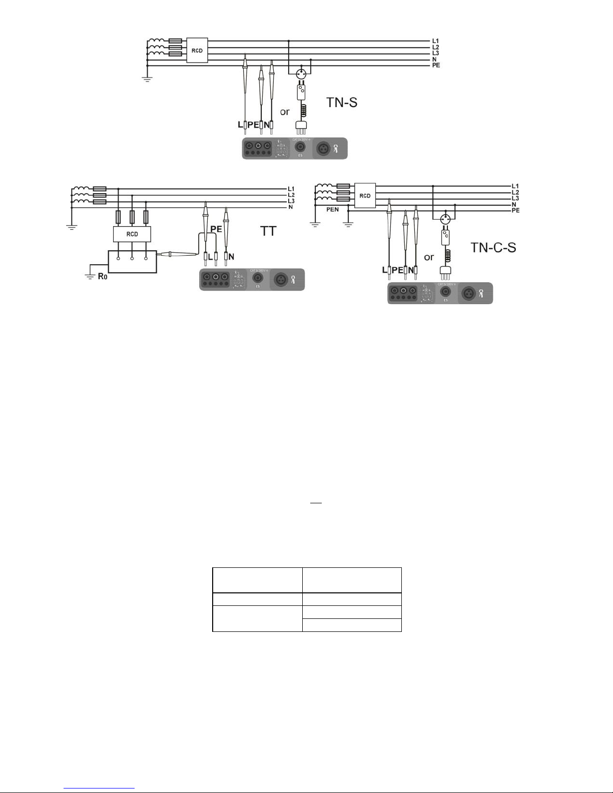
Measurement
Connect test leads according to one of the following drawings.
Page 26
OPERATING MANUAL MPI-530-IT version 1.06
24
Measurement in L-PE circuit
Checking effectiveness of protection against electric shock
of the housing in case of: a) TN b) TT.
The meter is ready for
measurement.
Make measurement by pressing START push-button.
Read out the result:
Z
L-PE
- the main result
Ia - current ensuring automatic triggering of a selected protective device in
a required time
Ik - prospective shortcircuit current
R, XL, U
L-PE
, f - additional
results.
The result is displayed on the screen for 20 s.
The result can be recalled by pressing ENTER push-button.
Page 27
OPERATING MANUAL MPI-530-IT version 1.06
25
Note:
- Double lead measurement is possible when a test lead other that the lead with a mains socket is selected.
- Remaining issues connected with the measurements as well as the messages displayed are the
same as those described for measurements in L-N circuit or L-L circuit.
3.4.3 Measurement of fault loop impedance in L-PE circuit protected with a
residual current device (RCD)
Settings
Set the rotary switch of function selection at
Z
L-PE
RCD position.
Press F1 push-button if L
lead length needs to be selected.
Use and to select the lead
length and press ENTER.
In order to set the security parameters press F2 .
Use , and , to set the
security parameters and press
ENTER.
Measurement
Connect test leads according to one of the drawings.
Page 28
OPERATING MANUAL MPI-530-IT version 1.06
26
Note:
- Maximum measurement time is about 32 seconds. The measurement can be interrupted by pressing ESC push-button.
- In the electrical installations with 30 mA RCD's, the sum of leakage currents of the installation and
the test current may trigger the RCD. If this happens, try to reduce the leakage current in the tested
mains (for example by disconnecting loads).
- Remaining issues connected with the measurements as well as the messages displayed are the
same as those described for measurements L-PE circuit.
- The function works for residual current devices of nominal current ≥ 30 mA.
3.4.4 Prospective short-circuit current
The meter always measures impedance ZS. The short-circuit current is calculated according to
the following formula:
S
k
Z
U
I
where: ZS - measured impedance, U - voltage that depends on settings of Ik button, according to the
following Table:
The selection in
MENU
Ik(Un)
U = Un
Ik(U0)
U = U0 for U0 < Un
U = Un for U0 ≥ Un
where: Un - nominal voltage of the network, U0 - the voltage during the measurement.
On the basis of Un rated voltage selected (section 2.2.1), the meter automatically recognizes the
measurement at phase-to-neutral or phase-to-phase voltage and takes it into account in the calculations.
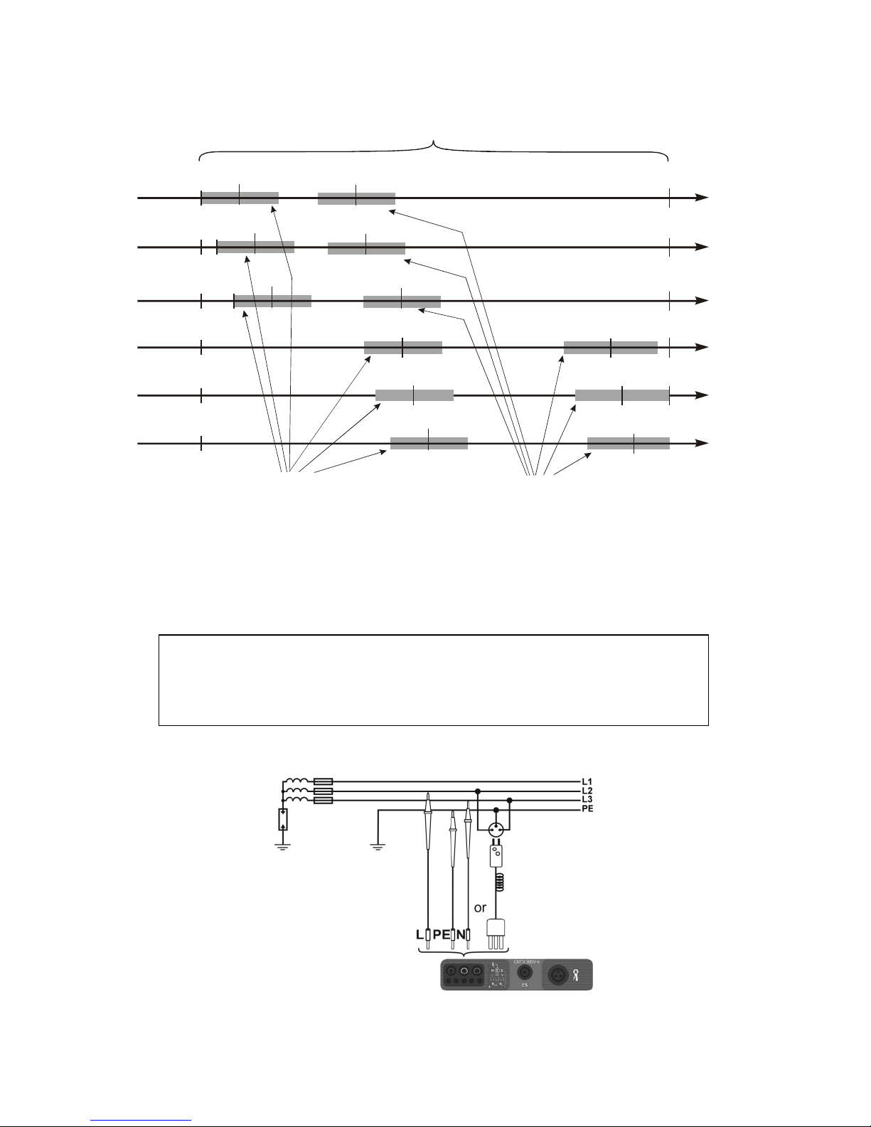
If the voltage of the network being tested is outside the tolerance range, the meter will not be able
to determine a proper rated voltage for the short-circuit current calculation. In such a case, horizontal
Page 29
OPERATING MANUAL MPI-530-IT version 1.06
27
dashes will be displayed instead of short-circuit current value. The following diagram shows voltage
ranges for which short-circuit current value is calculated.
230
400
440
U [V]
Zakresy napięć U , dla których
liczony jest prąd zwarciowy
L-N
Zakres napięcia, dla którego wykonywany
jest pomiar impedancji
207
253
360
115
127
180
200
220
220
380
418
198
242
342
373
415
440
216
240
264
103
440
U [V]
440
U [V]
U [V]
U =115 V
n
U =220 V
n
U =230 V
n
U =240 V
n
Zakresy napięć U , dla których
liczony jest prąd zwarciowy
L-L
110
121
171
190
209
99
440
U [V]
U =110 V
n
127
140
198
220
242
114
440
U [V]
U =127 V
n
99
99
99
99
99
3.4.5 Measurements in IT networks
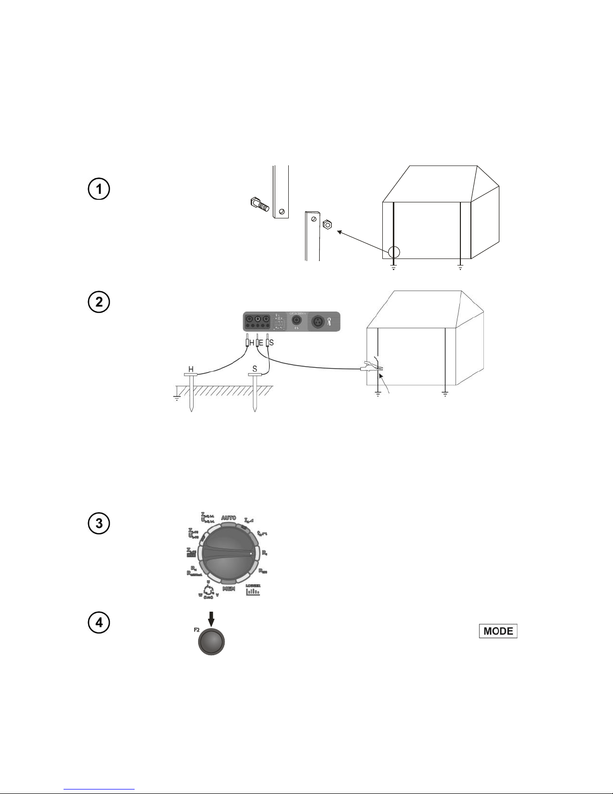
Before making measurements, the proper network type (earthing system) shall be set in main menu
of the meter, see point 2.2.1.
WARNING:
When IT network type (IT system) is chosen, touch electrode on the meter is disabled.
Connection of the meter to installation is show on the drawing below.
The voltage range for which the impedance
measurement is performed
The voltage range U
L-N,
for which the short-
circuit current is calculated
The voltage range U
L-L,
for which the short-
circuit current is calculated
Page 30
OPERATING MANUAL MPI-530-IT version 1.06
28
The way of making short circuit loop measurements is described in point 3.4.1. Operating voltage
range: 95 V … 440 V.
3.5 Measurement of resistance to earth
3.5.1 Measurement of resistance to earth using 3p method
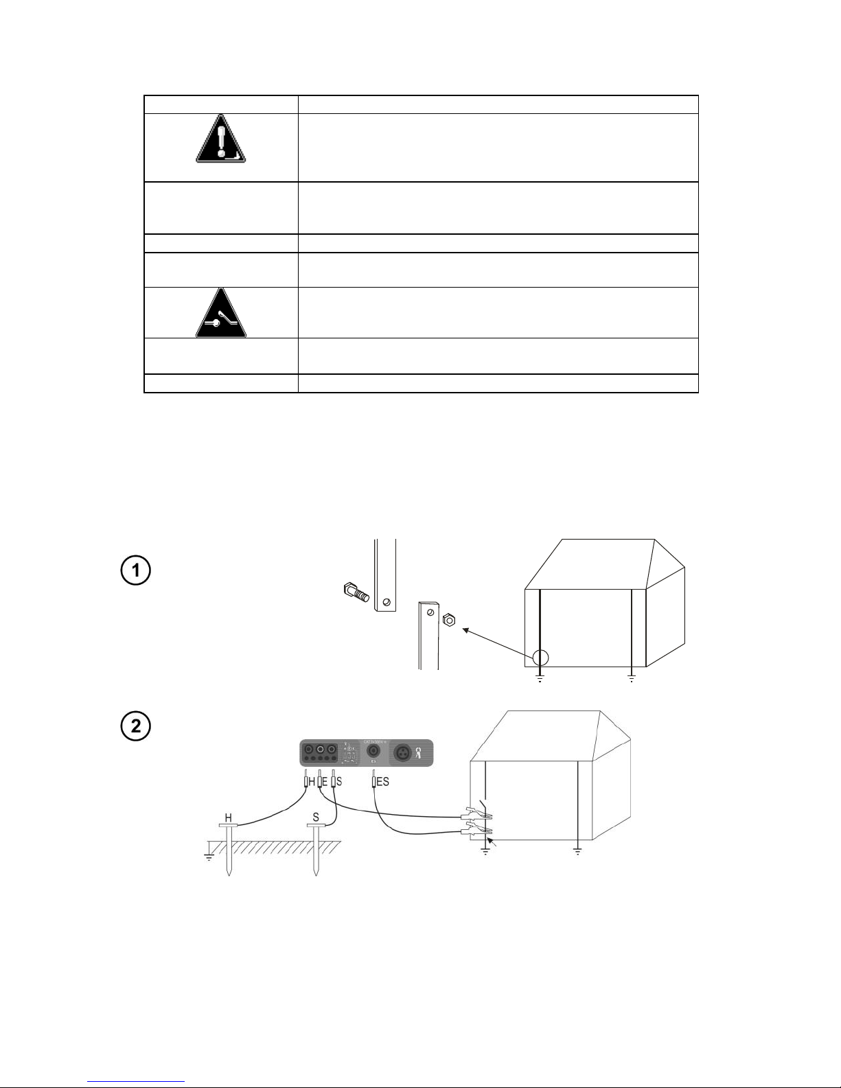
The three-lead measuring method is the basic type of resistance-to-earth measurement.
Disconnect the tested earth electrode from the system of the object.
The current electrode (driven into earth) should be connected to H socket of the meter.
The voltage electrode (driven into earth) should be connected to S socket of the meter.
The earth electrode being tested should be connected to E socket of the meter.
The tested earth electrode as well as current and voltage electrodes should be located along one
line and in the relevant distances, in accordance with the rules of earth measurements.
Settings
Turn the rotary switch to RE position.
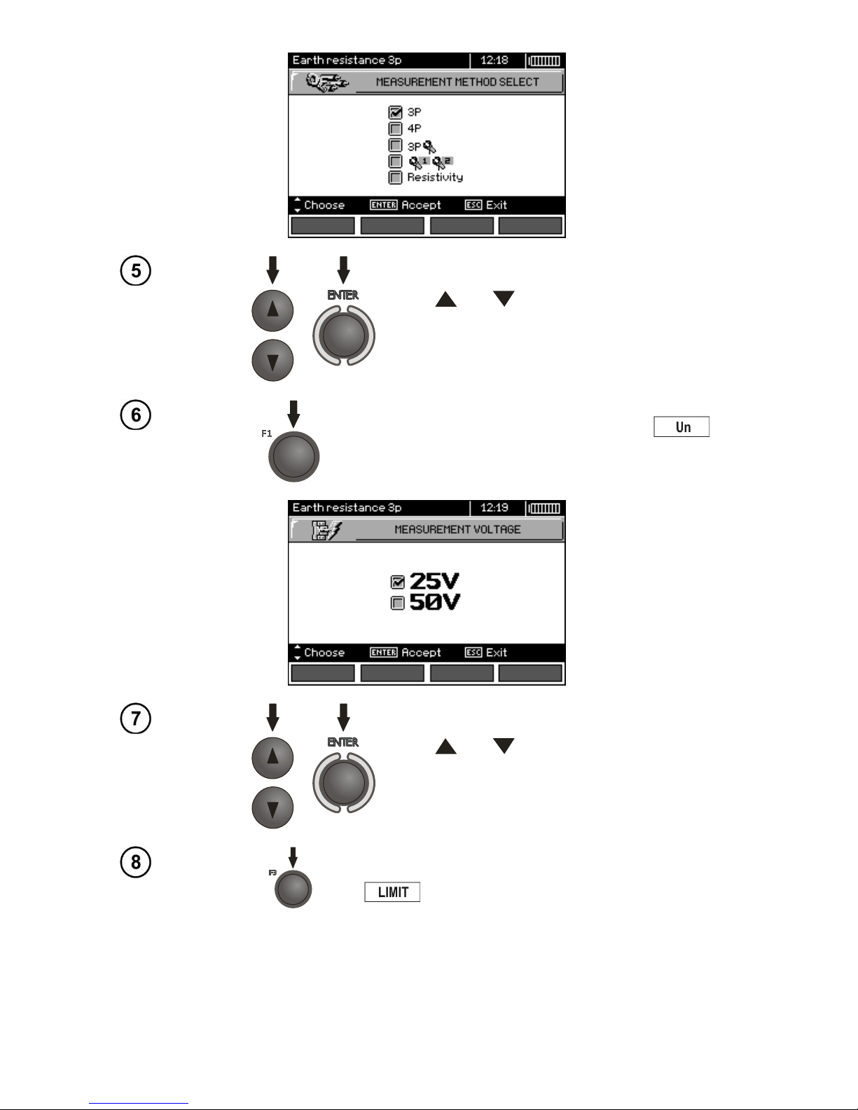
To select the measurement method press F2 .
Tested earth
electrode
Page 31
OPERATING MANUAL MPI-530-IT version 1.06
29
Use and to select 3P, confirm by pressing ENTER.
To change the measuring voltage press F1 .
Use and to select the measuring voltage,
confirm by pressing ENTER.
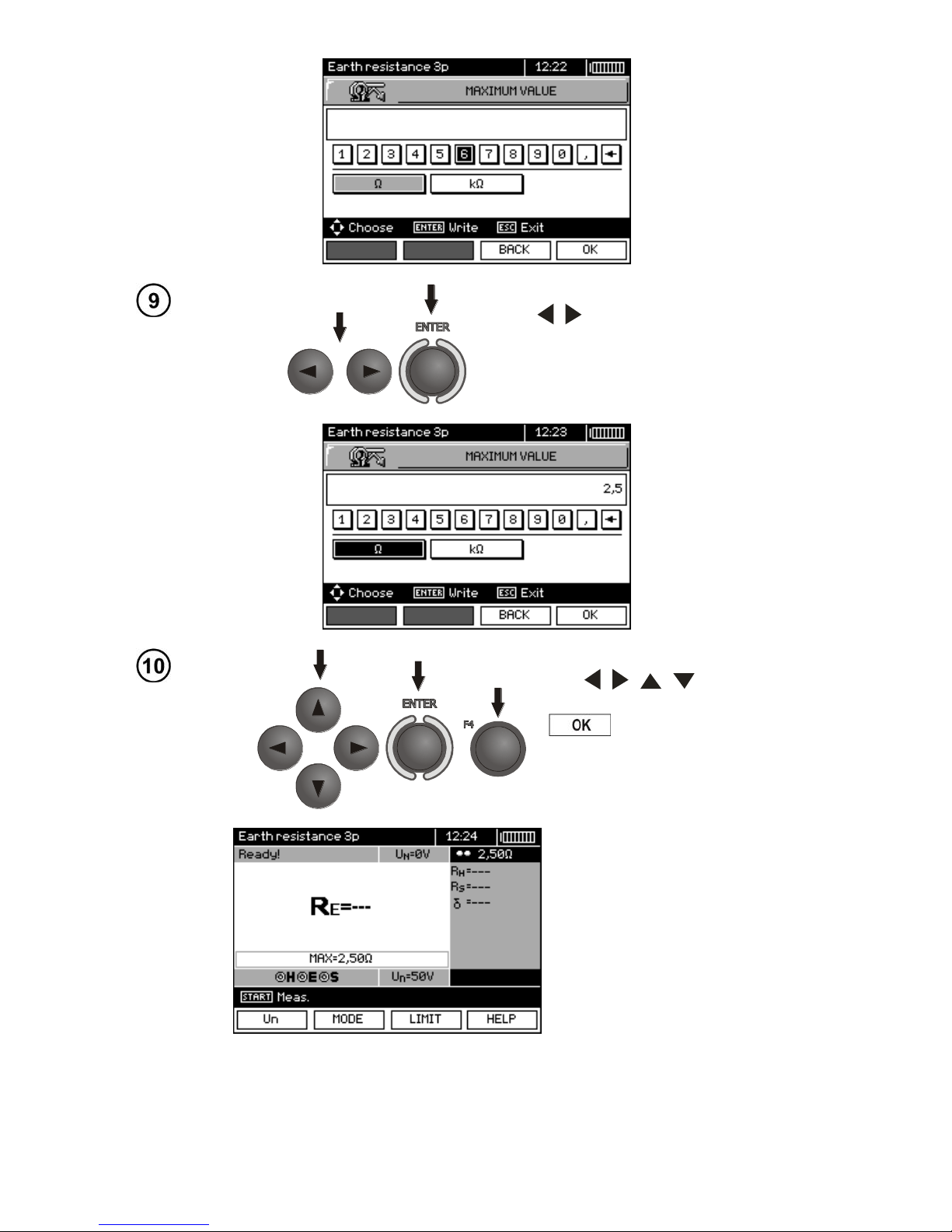
In order to set the limit (maximum resistance) press F3
.
Page 32
OPERATING MANUAL MPI-530-IT version 1.06
30
Use , and ENTER to enter the resistance value.
Use , , , and ENTER to
select unit, confirm by pressing F4
.
The meter is ready for measurement.
Value of interference voltage UN
of the measured object may be
read on the display.
Page 33
OPERATING MANUAL MPI-530-IT version 1.06
31
Measurement
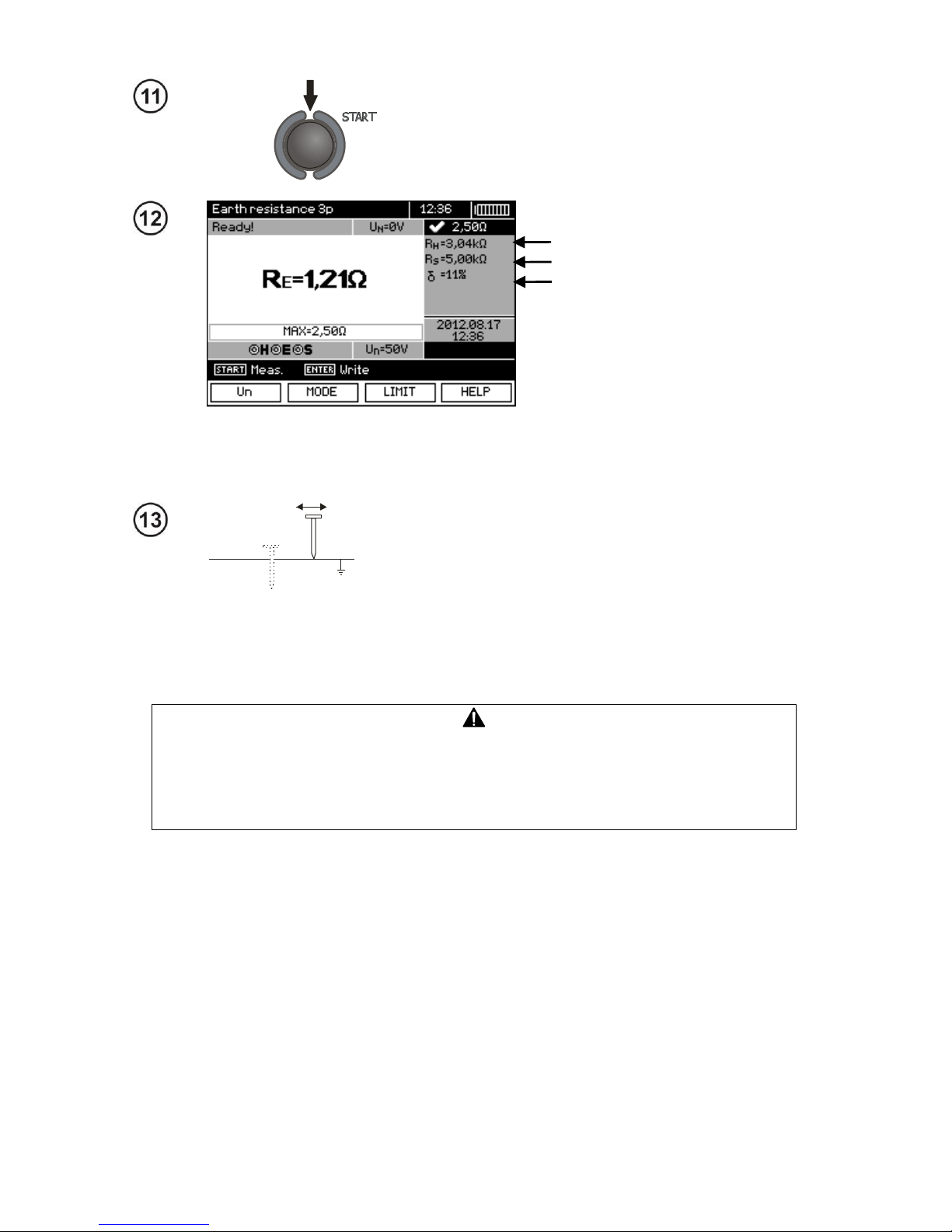
Press START push-button to start the measurement.
Read out the result.
Resistance of current electrode
Resistance of voltage electrode
The value of additional uncertainty,
generated by the resistance
of auxiliary electrodes
The result is displayed on the screen for 20 s.
The result can be recalled by pressing ENTER pushbutton.
S
Repeat the measurements (steps 2, 11, 12) moving the
voltage a few meters - placing it farther and closer to the
measured earth electrode. If RE measurement results differ from one another by more than 3 %, the distance of
the current electrode from the earth electrode being tested should be considerably increased and the measurements should be repeated.
Note:
Measurement of resistance-to-earth may be carried out if voltage of interferences does not exceed 24 V. Voltage of interferences is measured up to the
level of 100 V, but above 50 V it is signalled as dangerous. The meter must not
be connected to voltages exceeding 100 V.
- Particular attention should be paid to quality of connection between the object being tested and the
test lead – the contact area must be free from paint, rust, etc.
- If resistance of test probes is too high, RE earth electrode measurement will be burdened with additional uncertainty. Particularly high uncertainty of measurement occurs when a small value of resistance-to-earth is measured with probes that have a weak contact with earth (such a situation occurs frequently when the earth electrode is well made and the upper soil layer is dry and slightly conductive). In such a case, the ratio of resistance of the probes to resistance of the tested earth electrode is very high and consequently, uncertainty of measurement that depends on this ratio is also
very high. The uncertainty is displayed on the screen in the column of additional results. In order to
reduce the uncertainty, it is recommended to improve the contact between the probe and soil, for example, by dampening with water the place where the probe is driven into earth, driving the probe into
earth in a different place or using a 80 cm-long probe. Check also the test leads for possible insulation damage and for corroded or loosened connection between the banana plug and the test lead. In
majority of cases the achieved measurement accuracy is satisfactory. However, you should always
be aware of the uncertainty included in the measurement.
Page 34
OPERATING MANUAL MPI-530-IT version 1.06
32
Additional information displayed by the meter
R
E
>1.99 kΩ
Measuring range is exceeded.
UN
Voltage at test terminals is higher than 24 V but lower than
50 V, measurement is blocked.
UN>50V! and continuous, modulated au-
dio signal
Voltage at test terminals is higher than 50 V.
NOISE!
Signal / noise ratio is too low (interfering signal too large).
LIMIT!
Error due to the resistance of electrodes > 30 % (for calculating uncertainty, measured values are taken into account).
Interruption in measuring circuit or resistance of test probes
is higher than 60 kΩ.
Electrode resistance
>50 kΩ
Resistance of electrodes within the range of 50...60 kΩ.
ABORTED
Measurement has been interrupted with ESC key button.
3.5.2 Measurement of resistance to earth using 4p method
Four-pole method is recommended for use in the measurement of earth resistance of very small
values. It allows user to eliminate the influence of resistance of test leads on the measurement results. To determine the soil resistivity, it is recommended to use a function dedicated for this measurement (section 3.5.5).
Disconnect the tested earth electrode from the system of the object.
The current electrode (driven into earth) should be connected to H socket of the meter.
The voltage electrode (driven into earth) should be connected to S socket of the meter.
The earth electrode being tested should be connected to E socket of the meter with the lead.
ES socket should be connected to the tested earth electrode below E lead.
The tested earth electrode as well as current and voltage electrodes should be located along one
line and in the relevant distances, in accordance with the rules of earth measurements.
Tested earth
electrode
Page 35
OPERATING MANUAL MPI-530-IT version 1.06
33
Settings
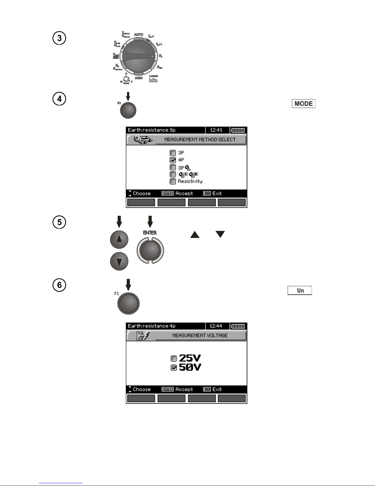
Set the rotary switch of function selection at RE
position.
To select the measurement method press F2 .
Use and to select 4P, confirm by pressing ENTER.
To change the measuring voltage, press F1 .
Page 36
OPERATING MANUAL MPI-530-IT version 1.06
34
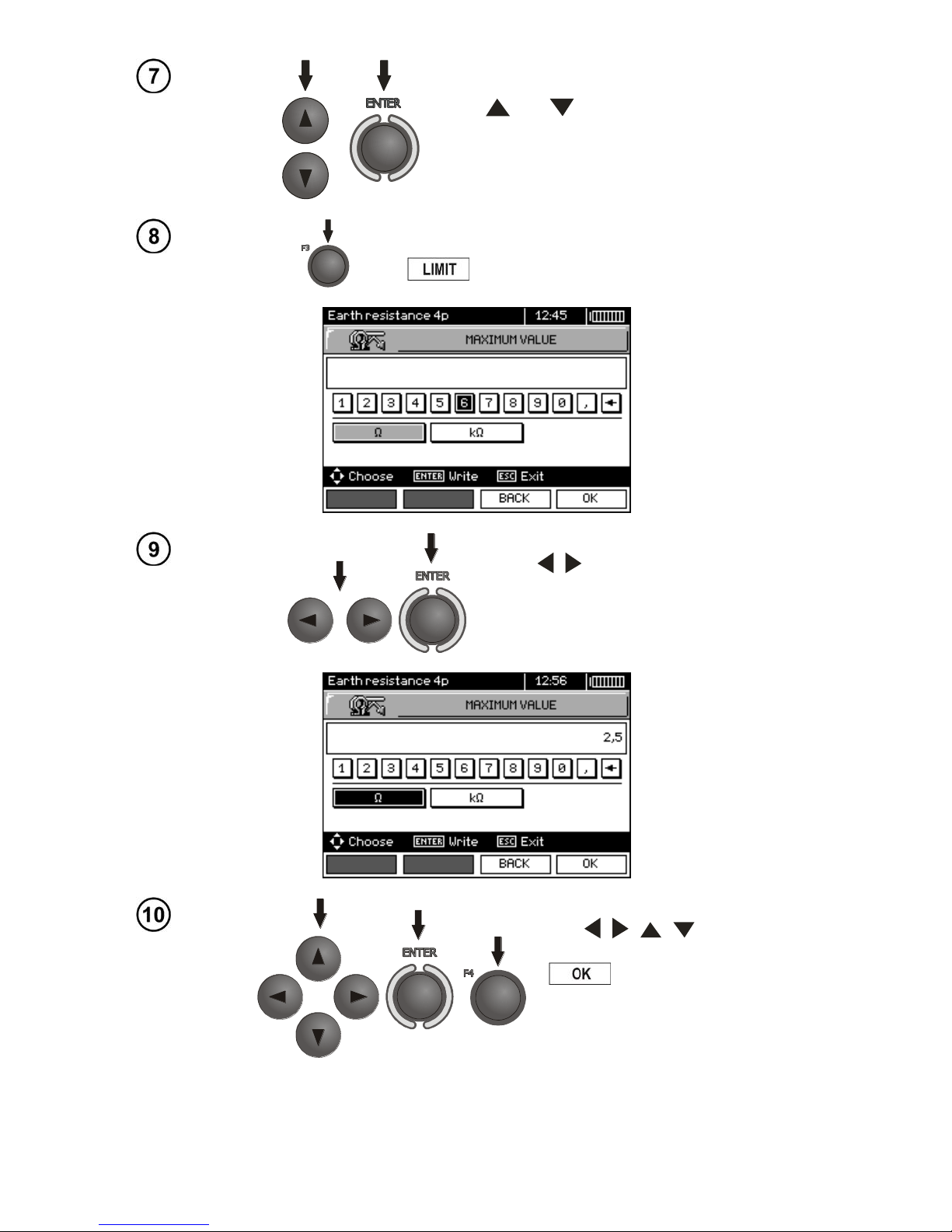
Use and to select the measuring voltage,
confirm by pressing ENTER.
In order to set the limit (maximum resistance), press F3
.
Use , and ENTER to enter the resistance value.
Use , , , and ENTER to
select unit. confirm by pressing F4
.
Page 37
OPERATING MANUAL MPI-530-IT version 1.06
35
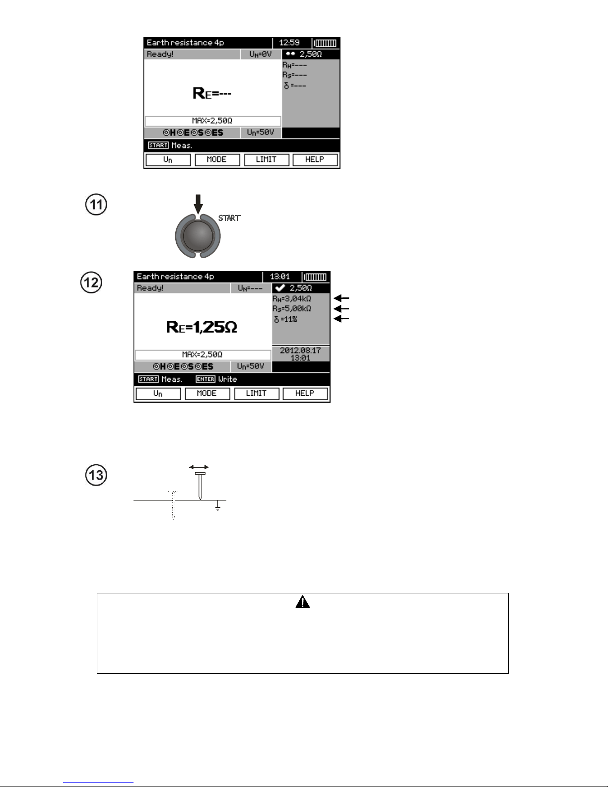
The meter is ready for measurement.
Value of interference voltage UN
of the measured object may be
read on the display.
Measurement
Press START push-button to start the measurement.
Read out the result.
Resistance of current electrode
Resistance of voltage electrode
The value of additional uncertainty,
generated by the resistance
of auxiliary electrodes
The result is displayed on the screen for 20 s.
The result can be recalled by pressing ENTER pushbutton.
S
Repeat the measurements (steps 2, 11, 12) moving the
voltage a few meters - placing it farther and closer to the
measured earth electrode. If RE measurement results differ from one another by more than 3 %, the distance of
the current electrode from the earth electrode being tested should be considerably increased and the measurements should be repeated.
Note:
Measurement of resistance-to-earth may be carried out if voltage of interferences does not exceed 24 V. Voltage of interferences is measured up to the
level of 100 V, but above 50 V it is signalled as dangerous. The meter must not
be connected to voltages exceeding 100 V.
- Particular attention should be paid to quality of connection between the object being tested and the
test lead – the contact area must be free from paint, rust, etc.
Page 38
OPERATING MANUAL MPI-530-IT version 1.06
36
- If resistance of test probes is too high, RE earth electrode measurement will be burdened with additional uncertainty. Particularly high uncertainty of measurement occurs when a small value of resistance-to-earth is measured with probes that have a weak contact with earth (such a situation occurs frequently when the earth electrode is well made and the upper soil layer is dry and slightly conductive). In such a case, the ratio of resistance of the probes to resistance of the tested earth electrode is very high and consequently, uncertainty of measurement that depends on this ratio is also
very high. Then, you can make a calculations according to the formulas given in sec. 10.2 to estimate
the influence of measurement conditions or you can use the graph also included in the appendix. You
can improve the contact between the probe and soil, for example, by dampening with water the place
where the probe is driven into earth, driving the probe into earth in a different place or using a 80 cmlong probe. Check also the test leads for possible insulation damage and for corroded or loosened
connection between the banana plug and the test lead. In majority of cases the achieved measurement accuracy is satisfactory. However, you should always be aware of the uncertainty included in
the measurement.
Additional information displayed by the meter
R
E
>1,99 kΩ
Measuring range is exceeded.
UN>50V! and con-
tinuous, modulated
audio signal
Voltage at test terminals is higher than 50 V, measurement is blocked.
UN
Voltage at test terminals is higher than 24 V but lower
than 50 V, measurement is blocked.
LIMIT!
The uncertainty due to the resistance of electrodes > 30
%. (For calculating uncertainty, measured values are taken into account.)
NOISE!
The interfering signal (noise signal) is too high - the
measurement result may be affected by additional uncertainty.
3.5.3 Measurement of resistance to earth using 3p + clamps method
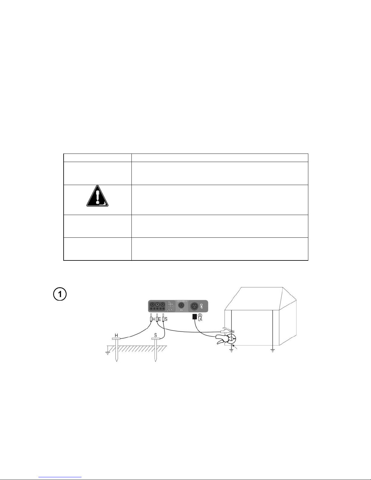
The current electrode (driven into earth) should be connected to H socket of the meter.
The voltage electrode (driven into earth) should be connected to S socket of the meter.
The earth electrode being tested should be connected to E socket of the meter with the lead.
The tested earth electrode as well as current and voltage electrodes should be located along one
line and in the relevant distances, in accordance with the rules of earth measurements.
Clamps should be attached to the tested earth electrode below the connection point of E lead.
Tested earth
electrode
Page 39
OPERATING MANUAL MPI-530-IT version 1.06
37
Settings
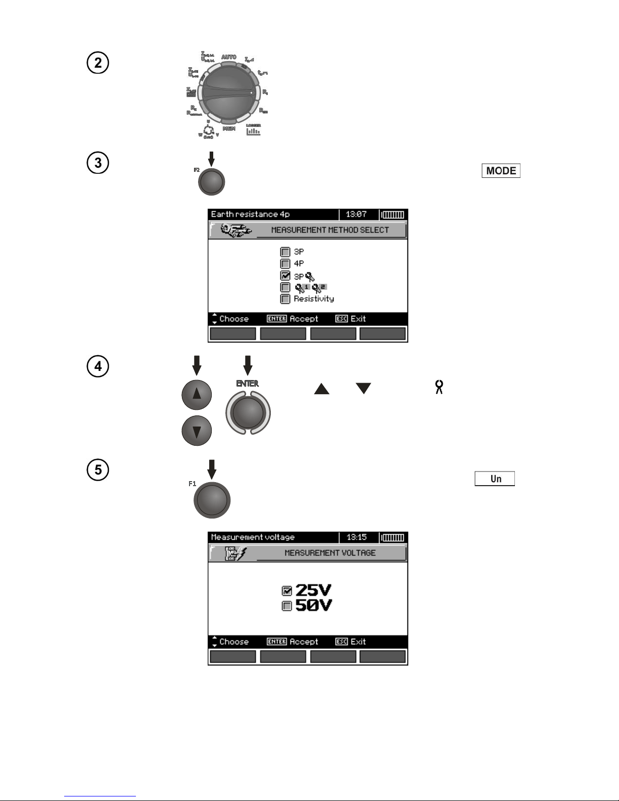
Set the rotary switch of function selection at
RE position.
To select the measurement method press F2 .
Use and to select 3P , confirm by
pressing ENTER.
To change the measuring voltage, press F1 .
Page 40
OPERATING MANUAL MPI-530-IT version 1.06
38
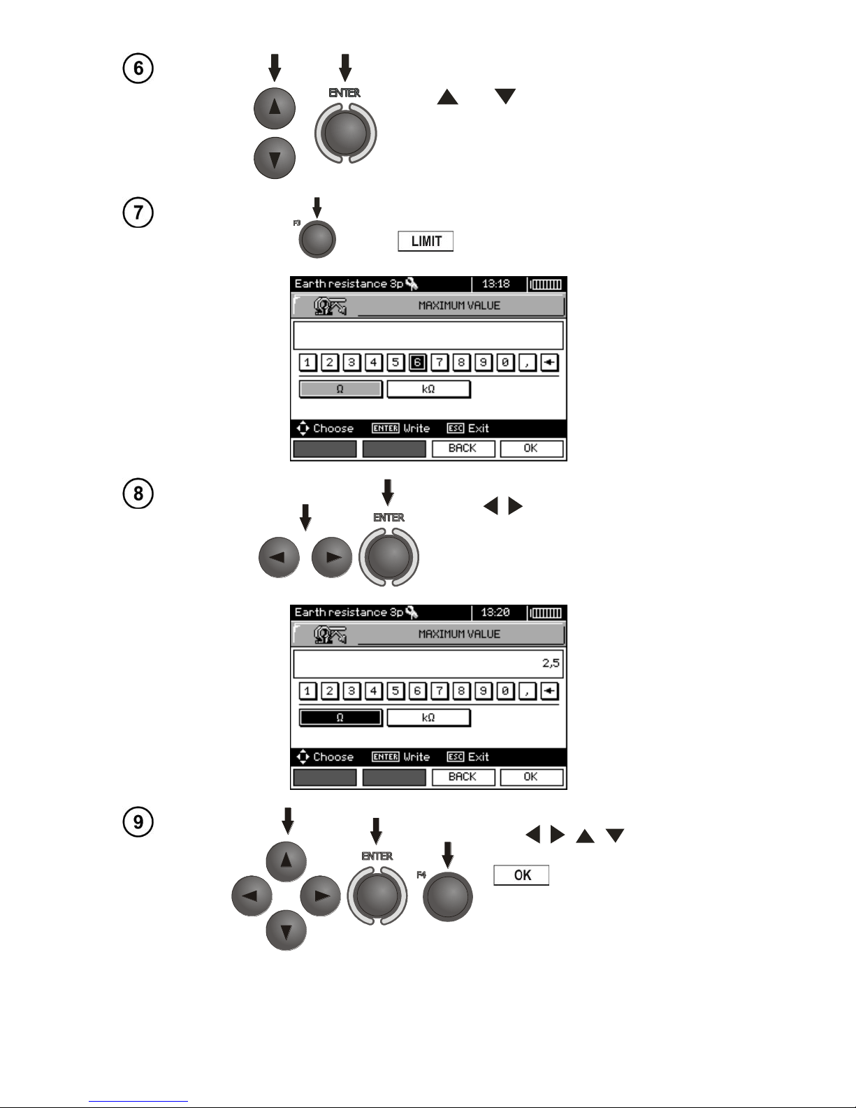
Use and to select the measuring voltage,
confirm by pressing ENTER.
In order to set the limit (maximum resistance), press
F3 .
Use , and ENTER to enter the resistance value.
Use , , , and ENTER to
select unit, confirm by pressing F4
.
Page 41
OPERATING MANUAL MPI-530-IT version 1.06
39
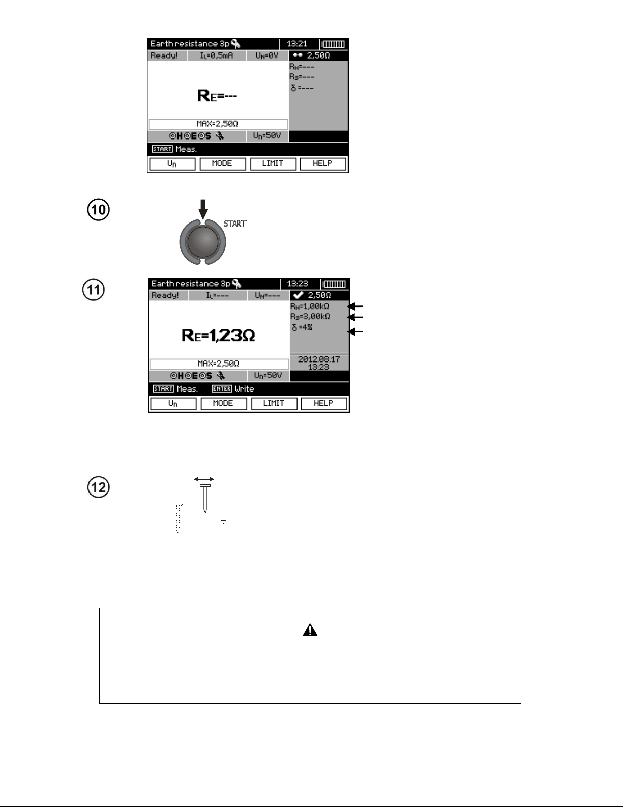
The meter is ready for measurement.
The user may read the value of
interference voltage UN and the
value of the leakage current flowing through the clamps in the
tested object.
Measurement
Press START push-button to start the measurement.
Read out the result.
Resistance of current electrode
Resistance of voltage electrode
The value of additional uncertainty,
generated by the resistance
of auxiliary electrodes
The result is displayed on the screen for 20 s.
The result can be recalled by pressing ENTER pushbutton.
S
Repeat the measurements (steps 1, 10, 11) moving the
voltage a few meters - placing it farther and closer to the
measured earth electrode. If RE measurement results differ from one another by more than 3 %, the distance of
the current electrode from the earth electrode being tested should be considerably increased and the measurements should be repeated.
Note:
Measurement of resistance-to-earth may be carried out if voltage of interferences does not exceed 24 V. Voltage of interferences is measured up to the
level of 100 V, but above 50 V it is signalled as dangerous. The meter must not
be connected to voltages exceeding 100 V.
Page 42
OPERATING MANUAL MPI-530-IT version 1.06
40
- Use C-3 clamps for the measurement. Clamps purchased with the meter must be calibrated before
their first use. They may be periodically calibrated in order to prevent their ageing influence the accuracy of the measurements. Option for the calibration of clamps is included in the MENU.
- Maximum interference current: 1 A.
- Particular attention should be paid to quality of connection between the object being tested and the
test lead – the contact area must be free from paint, rust, etc.
- If resistance of test probes is too high, RE earth electrode measurement will be burdened with additional uncertainty. Particularly high uncertainty of measurement occurs when a small value of resistance-to-earth is measured with probes that have a weak contact with earth (such a situation occurs frequently when the earth electrode is well made and the upper soil layer is dry and slightly conductive). In such a case, the ratio of resistance of the probes to resistance of the tested earth electrode is very high and consequently, uncertainty of measurement that depends on this ratio is also
very high. Then, you can make a calculations according to the formulas given in sec. 10.2 to estimate
the influence of measurement conditions or you can use the graph also included in the appendix. You
can improve the contact between the probe and soil, for example, by dampening with water the place
where the probe is driven into earth, driving the probe into earth in a different place or using a 80 cmlong probe. Check also the test leads for possible insulation damage and for corroded or loosened
connection between the banana plug and the test lead. In majority of cases the achieved measurement accuracy is satisfactory. However, you should always be aware of the uncertainty included in
the measurement.
- Factory calibration does not include the resistance of the test leads. The result displayed by the meter is a sum of the resistance of the measured object and the resistance of leads.
Additional information displayed by the meter
R
E
>1.99 kΩ
Measuring range is exceeded.
UN>50V! and con-
tinuous, modulated
audio signal
Voltage at test terminals is higher than 50 V, measurement is blocked.
UN
Voltage at test terminals is higher than 24 V but lower
than 50 V, measurement is blocked.
NOISE!
The interfering signal (noise signal) is too high - the
measurement result may be affected by additional uncertainty.
LIMIT!
The uncertainty due to the resistance of electrodes > 30
%. (For calculating uncertainty, measured values are taken into account.)
IL>max
The interference current is too high, the measurement error may be larger than the basic error.
3.5.4 Measurement of resistance to earth using double clamp method
The double-clamp measurement may be applied where there is no possibility to use electrodes
driven into the ground.
ATTENTION!
The double-clamp method may be only for multiple earthing measurements.
Page 43
OPERATING MANUAL MPI-530-IT version 1.06
41
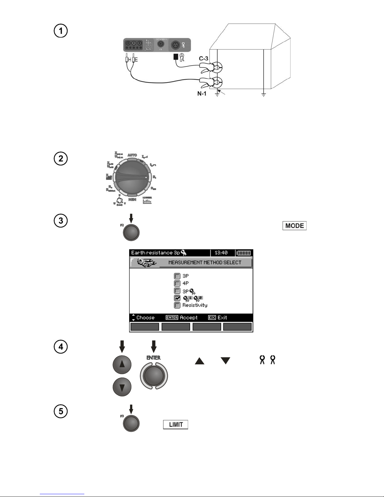
Transmitting clamps and measuring clamps should be attached to the tested earth electrode at a distance of at least 30 cm from each other.
Connect transmitting clamps to H and E sockets, whereas the measuring clamps to the clamp
socket.
Settings
Set the rotary switch of function selection at RE position.
To select the measurement method, F2 .
Use and to select 1 2, confirm by
pressing ENTER.
In order to set the limit (maximum resistance) press F3
.
Tested earth
electrode
Page 44
OPERATING MANUAL MPI-530-IT version 1.06
42
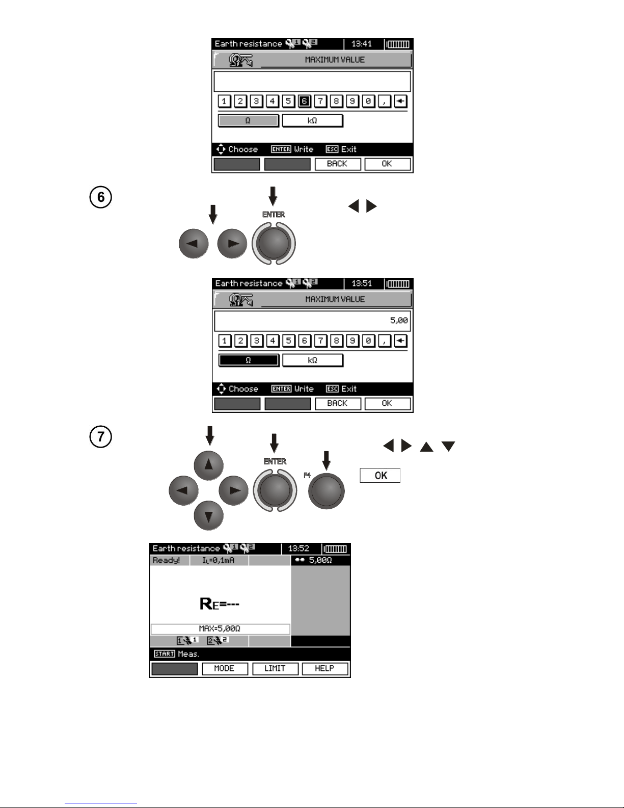
Use , and ENTER to enter the resistance value.
Use , , , and ENTER to
select unit, confirm by pressing F4
.
The meter is ready for measurement.
The display shows the value of
the leakage current flowing
through the clamps.
Page 45
OPERATING MANUAL MPI-530-IT version 1.06
43
Measurement
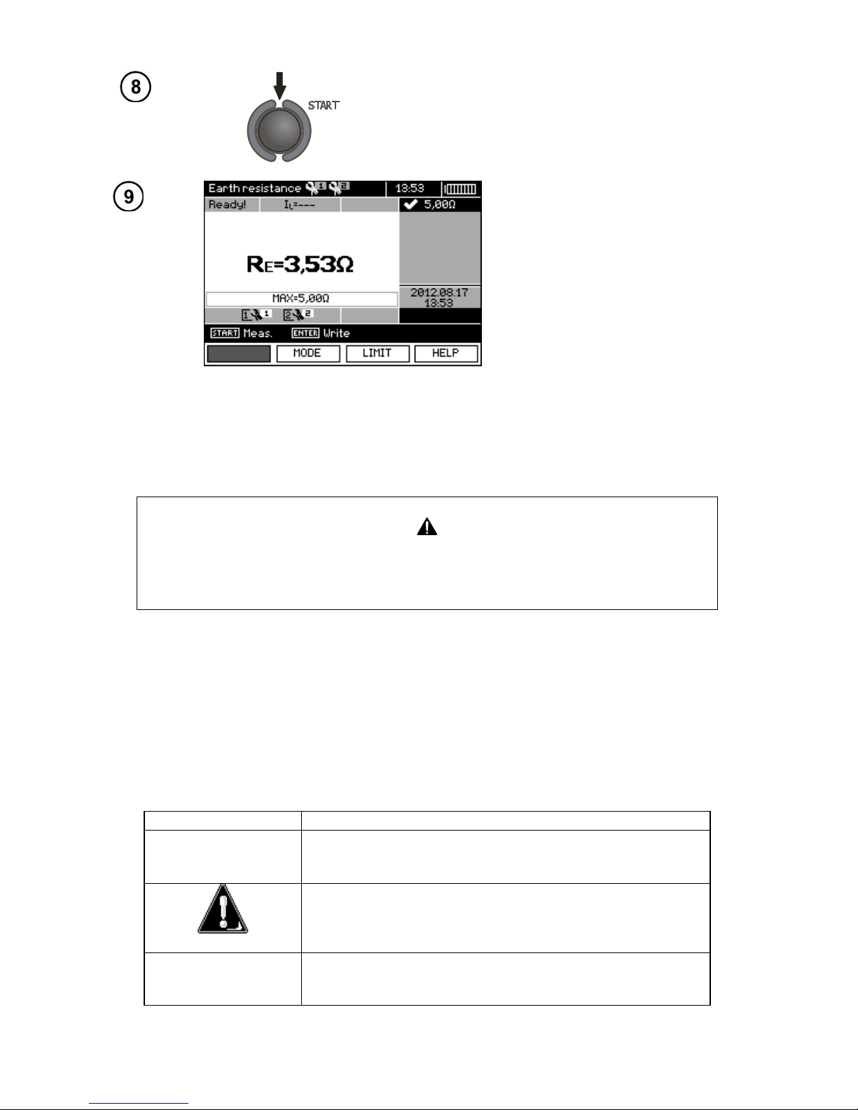
Press STARTpush-button to start the measurement.
Read out the result.
The result is displayed on the screen for 20 s.
The result can be recalled by pressing ENTER pushbutton.
Note:
Measurements may be performed in the presence of interference current of a
value not exceeding 3 A rms and frequency in accordance with the value set in
MENU.
- Use N-1 clamps as signal transmitting clamps and C-3 clamps as receiving clamps. C-3 clamps
purchased with the meter must be calibrated before their first use. They may be periodically calibrated in order to prevent their ageing influence the accuracy of the measurements. Option for the calibration of clamps is included in the MENU.
- If the current on measuring clamps is too low, the meter displays the following message: "Meas-
ured current is too low, measurement impossible!".
- Maximum interference current: 1 A.
Additional information displayed by the meter
R
E
>99.9Ω
Measuring range is exceeded.
UN>50V! and con-
tinuous, modulated
audio signal
Voltage at test terminals is higher than 50 V, measurement is blocked.
UN
Voltage at test terminals is higher than 24 V but lower
than 50 V, measurement is blocked.
NOISE!
The interfering signal (noise signal) is too high - the
measurement result may be affected by additional uncertainty.
Page 46
OPERATING MANUAL MPI-530-IT version 1.06
44
3.5.5 Measuring soil resistivity
For soil resistivity measurements - used as preparation for the designing the earthing system or
in geology measurements - a separate function is provided: measurement of soil resistivity.. This
function is identical to 4-pole measurement of earth resistance, however, it contains an additional
procedure of entering the distance between the electrodes. The measurement result is the resistivity
value, calculated automatically according to the following formula: ρ = 2LRE, applied in Wenner
method. This method assumes equal distances between the electrodes.
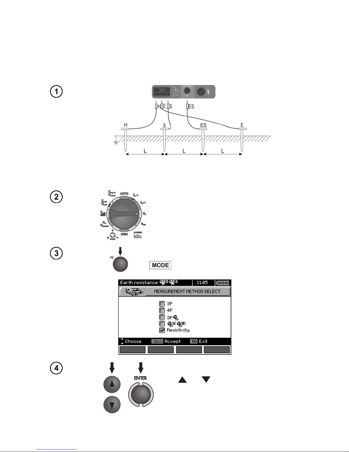
Four probes driven into the ground along one line and in equal distances must be connected as
shown in the picture above.
Settings
Set the rotary switch of function selection at RE position.
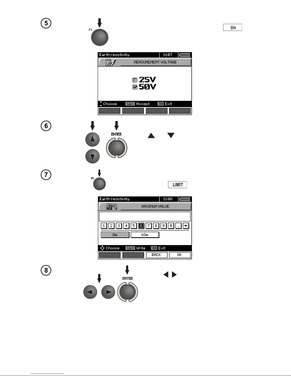
To select the resistivity measurement, press F2
.
Use and to select Resistivity, confirm by
pressing ENTER.
Page 47
OPERATING MANUAL MPI-530-IT version 1.06
45
To change the measuring voltage, press F1 .
Use and select the measuring voltage,
confirm by pressing ENTER.
In order to set the limit (maximum allowable resistance), press F3 .
Use , and ENTER to enter the allowed maximum value of resistivity.
Page 48
OPERATING MANUAL MPI-530-IT version 1.06
46
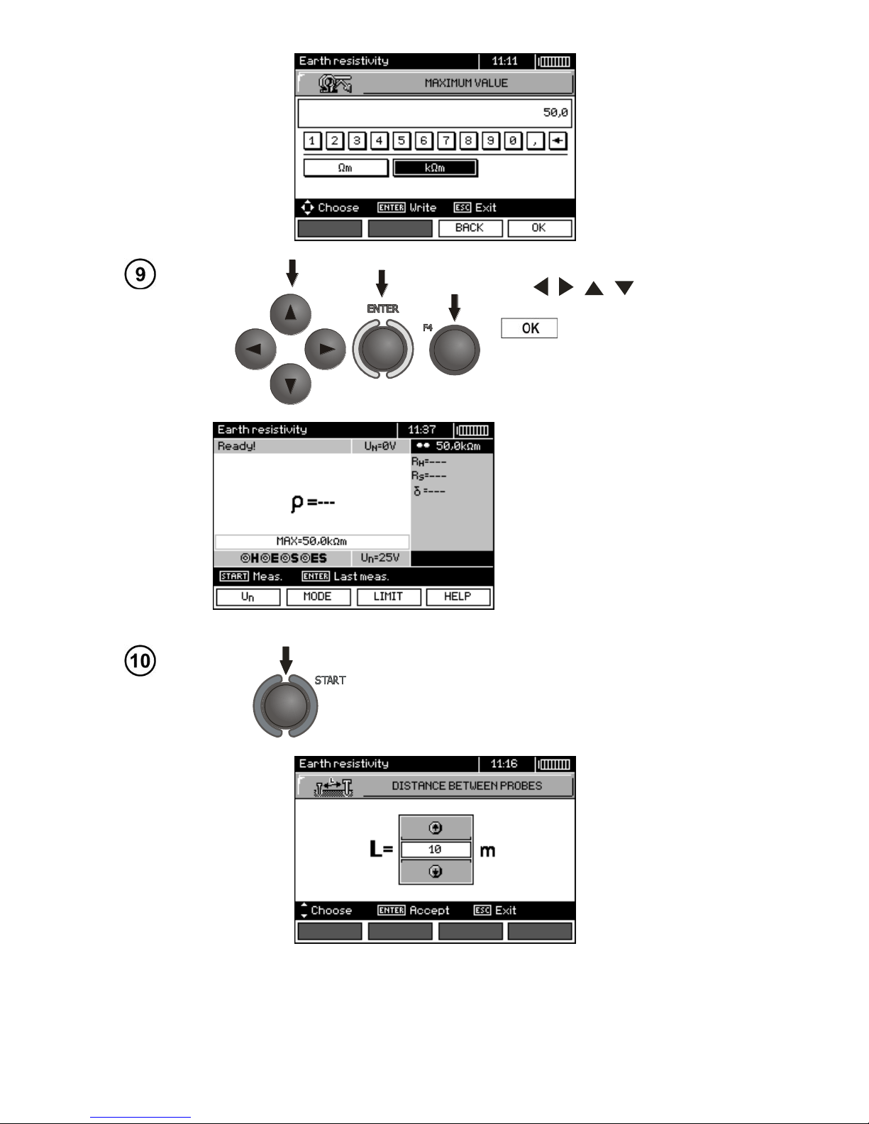
Use , , , and ENTER to
select unit, confirm by pressing F4
.
The meter is ready for measurement.
Value of interference voltage UN
of the measured object may be
read on the display.
Measurement
Press START, to enter into the mode of setting the
distance between the probes.
Page 49
OPERATING MANUAL MPI-530-IT version 1.06
47
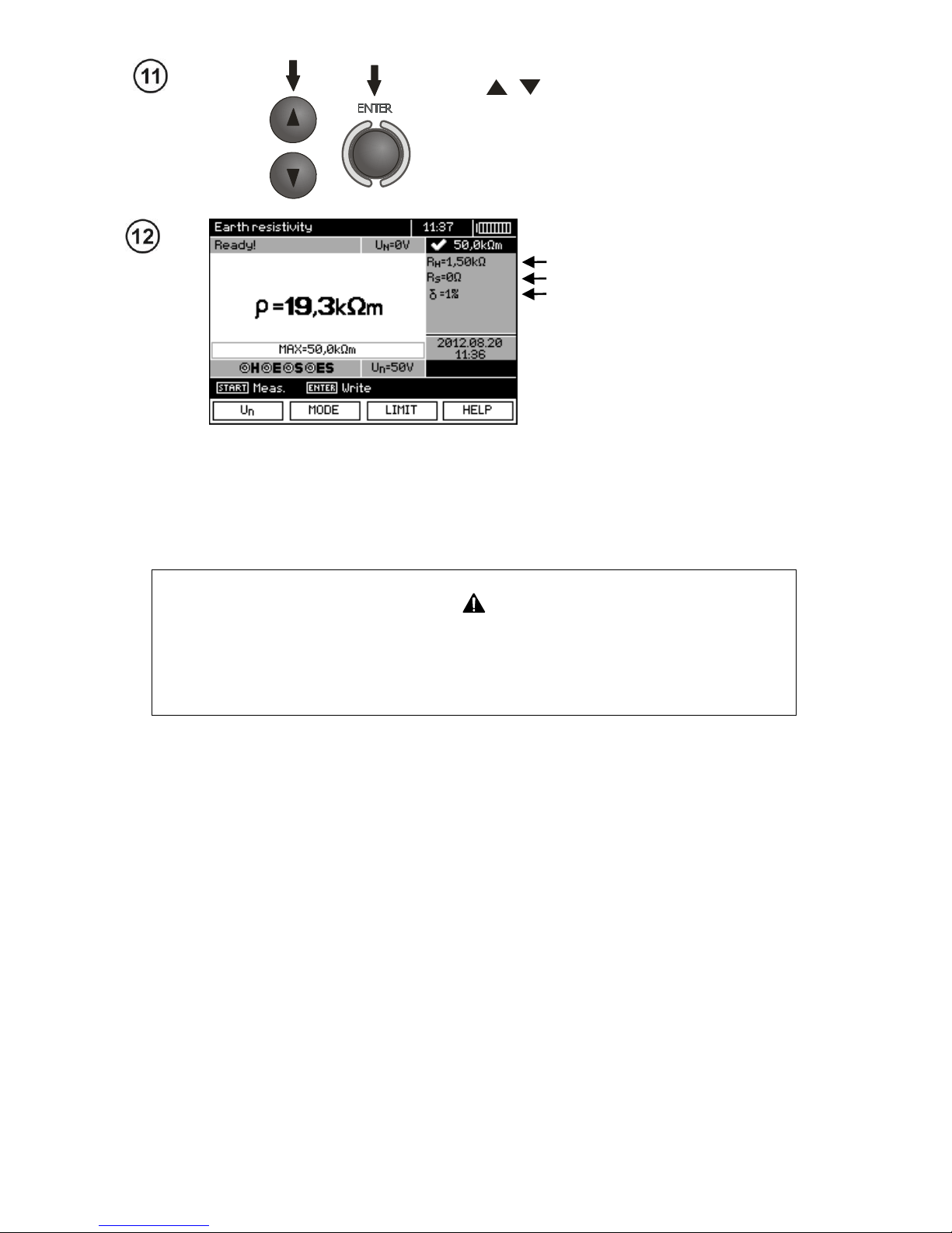
Use , to select the distance between the
probes, and press ENTER to trigger the measurement.
Read out the result.
Resistance of current electrode
Resistance of voltage electrode
The value of additional uncertainty,
generated by the resistance
of auxiliary electrodes (probes)
The result is displayed on the screen for 20s.
The result can be recalled by pressing ENTER pushbutton.
Note:
Measurement of resistivity earth may be carried out if voltage of interferences
does not exceed 24 V. Voltage of interferences is measured up to the level of
100 V, but above 50 V it is signalled as dangerous. The meter must not be connected to voltages exceeding 100 V.
- The calculations assume that the distance between the measuring electrodes are equal (Wenner
method). If it is not the case, perform the measurement of earth resistance using 4-pole method and
perform calculations by yourself.
- Particular attention should be paid to quality of connection between the object being tested and the
test lead – the contact area must be free from paint, rust, etc.
- If resistance of test probes is too high, RE earth electrode measurement will be burdened with additional uncertainty. Particularly high uncertainty of measurement occurs when a small value of resistance-to-earth is measured with probes that have a weak contact with earth (such a situation occurs frequently when the earth electrode is well made and the upper soil layer is dry and slightly conductive). In such a case, the ratio of resistance of the probes to resistance of the tested earth electrode is very high and consequently, uncertainty of measurement that depends on this ratio is also
very high. Then, you can make a calculations according to the formulas given in sec. 10.2 to estimate
the influence of measurement conditions or you can use the graph also included in the appendix. You
can improve the contact between the probe and soil, for example, by dampening with water the place
where the probe is driven into earth, driving the probe into earth in a different place or using a 80 cmlong probe. Check also the test leads for possible insulation damage and for corroded or loosened
connection between the banana plug and the test lead. In majority of cases the achieved measurement accuracy is satisfactory. However, you should always be aware of the uncertainty included in
the measurement.
Page 50
OPERATING MANUAL MPI-530-IT version 1.06
48
Additional information displayed by the meter
R
E
>99.9kΩm
Measuring range is exceeded.
UN>50V! and con-
tinuous, modulated
audio signal
Voltage at test terminals is higher than 50 V, measurement is blocked.
UN
Voltage at test terminals is higher than 24 V but lower
than 50 V, measurement is blocked.
LIMIT!
The uncertainty due to the resistance of electrodes > 30
%. (For calculating uncertainty, measured values are taken into account.)
NOISE!
The interfering signal (noise signal) is too high - the
measurement result may be affected by additional uncertainty.
3.6 Measurement of RCD parameters
Note:
The measurement of UB, RE is always performed with sinusoidal current 0,4I
n
, regardless of
the settings concerning waveform and multiplication factor I
n
.
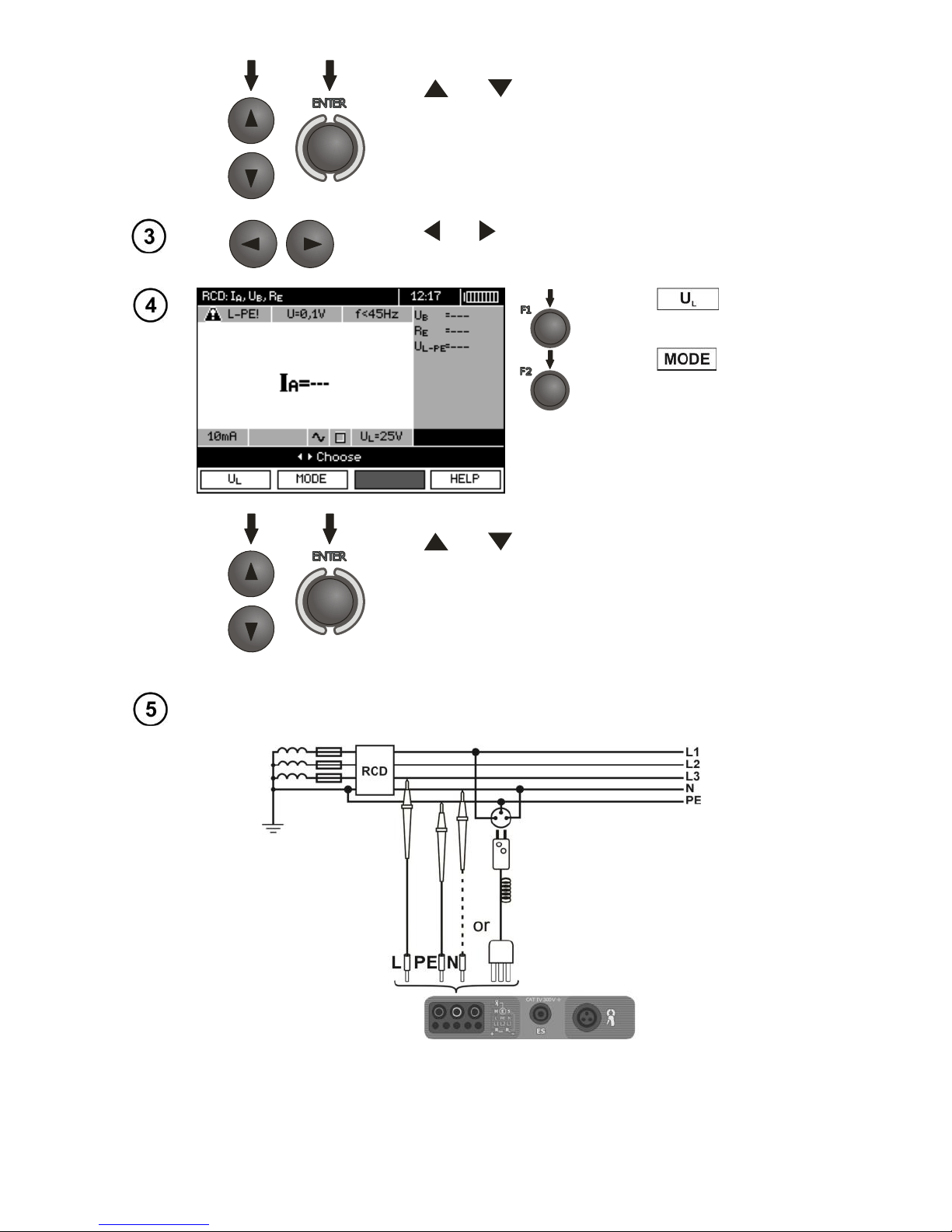
3.6.1 Measurement of RCD disconnection current
Settings
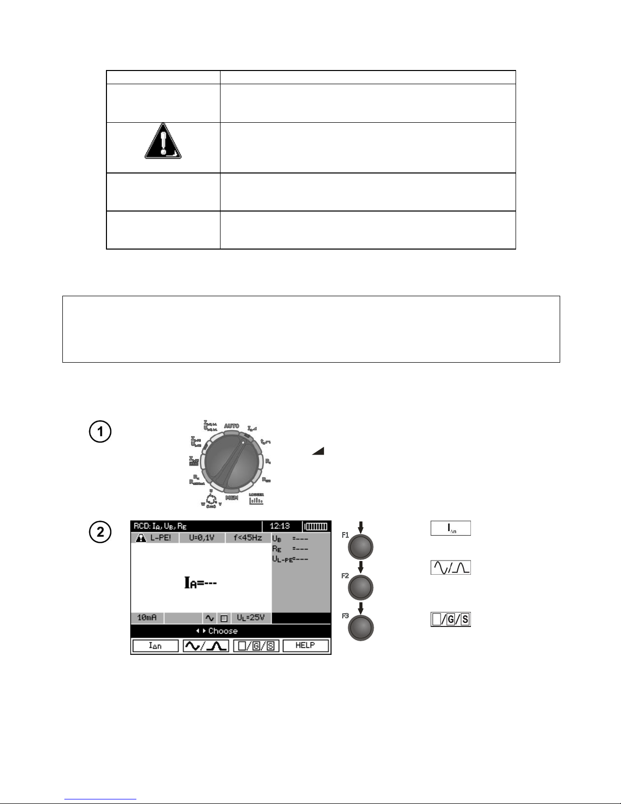
Set the rotary switch of function selection at
IA position.
Press F1
to enter In
selection mode.
Press F2
to enter the
selection mode for current
waveform.
Press F3 to enter RCD
type selection mode.
Page 51
OPERATING MANUAL MPI-530-IT version 1.06
49
Use and
to select desired position and press
ENTER to confirm.
Use and to enter the second group of parameters.
Press F1
to enter UL
selection mode.
Press F2
and move to
selection of measurement
mode.
Use and
to select desired position and press
ENTER to confirm.
Measurement
Connect the meter to the installation according to the drawing.
Page 52
OPERATING MANUAL MPI-530-IT version 1.06
50
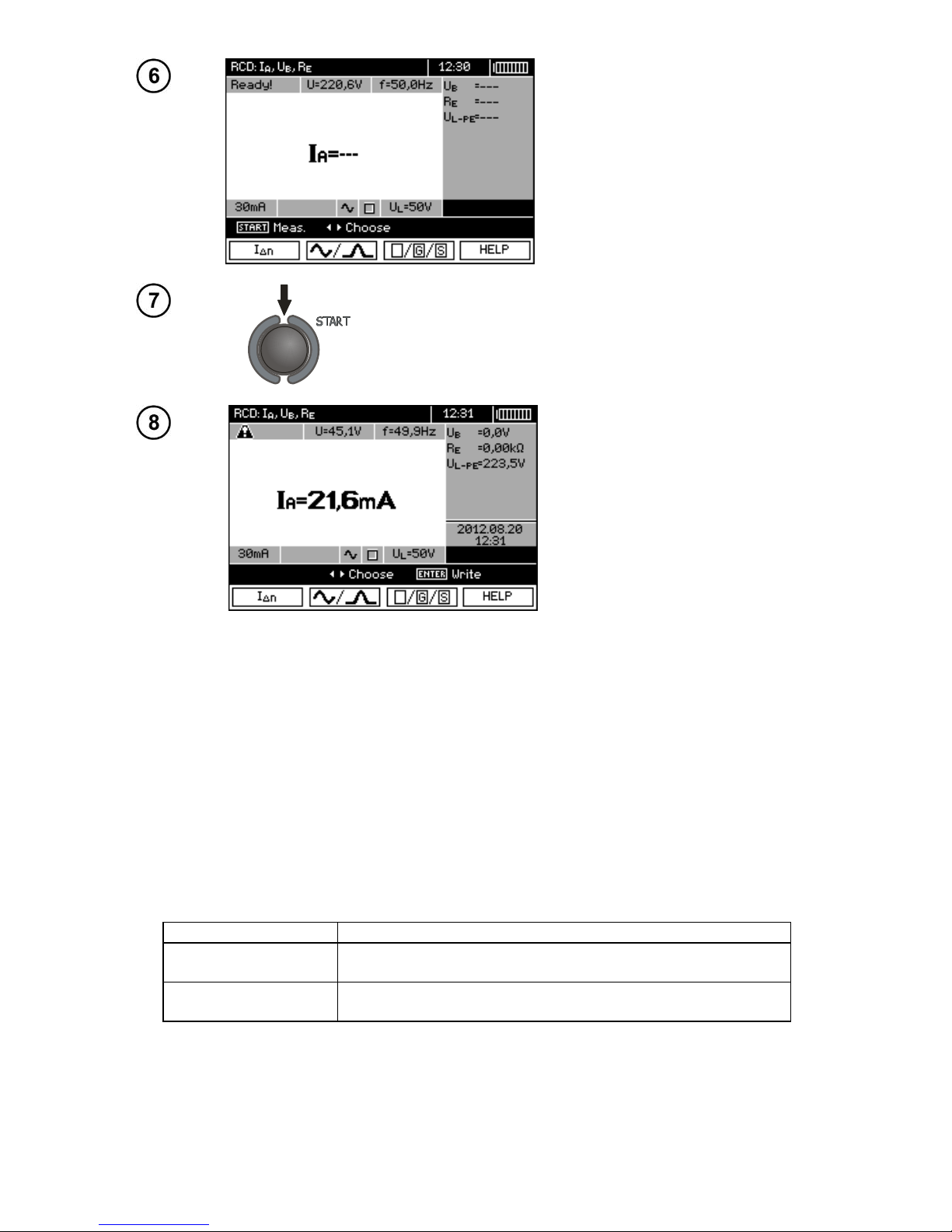
The meter is ready for measurement.
Value of network voltage and frequency can be read on the display.
Press START to begin measurement.
Read out the result.
Note:
- Measurement of disconnection time tAI (tA measured during IA measurement) for selective RCD is
not available.
- The measurement of response time tAI is not performed as required by applicable standards (i.e with
RCD nominal current In), but with IA current measured and displayed during the measurement. But in
most cases where the measurement does not have to be strictly as defined by the standard, this
measurement may be taken into account to assess the proper operation of RCD protection in a particular installation. When measured IA is lower than In (most frequent case), then response time tAI
will be usually longer than the response time measured in function tA, which measures the time at In
current. Therefore, when time tAI is s correct (not too long), it may be assumed that the time measured in function tA would be also correct (it would not be longer).
Additional information displayed by the meter
UB>UL!
The touch voltage exceeds a preset ULthreshold value.
!
Displayed on the right side of the result indicates a fault of
RCD.
No U
L-N
!
Lack of neutral lead that is necessary for IΔn constant and
pulsed with direct current offset
The remaining information is the same as for fault loop measurement (first 7 positions in the table of
section 3.4.1).
Page 53
OPERATING MANUAL MPI-530-IT version 1.06
51
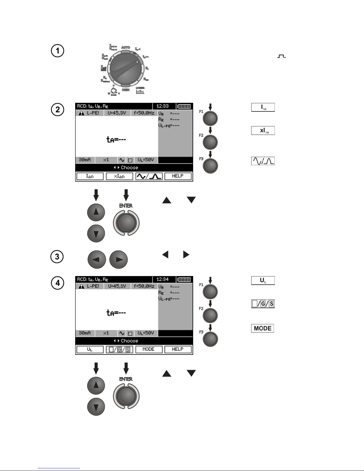
3.6.2 Measurement of RCD disconnection time
Settings
Turn the rotary switch to tA position. .
Press F1 to enter In
selection mode.
Press F2
to enter In
multiplication factor selection
mode.
Press F3 to enter the
selection mode for current
waveform.
Use and
to select desired position and press
ENTER to confirm.
Use and to enter the second group of parameters.
Press F1 to enter UL
selection mode.
Press F2 to enter RCD
type selection mode.
Press F3 and move to
selection of measurement
mode.
Use and
to select a suitable position and press
ENTER to confirm.
Page 54
OPERATING MANUAL MPI-530-IT version 1.06
52
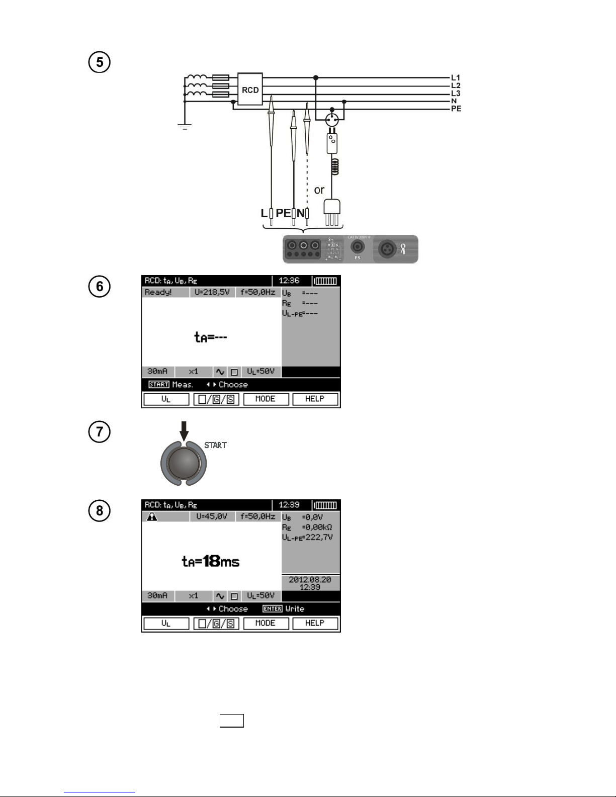
Measurement
Connect the meter to the installation according to the drawing.
The meter is ready for measurement.
Value of network voltage and frequency can be read on the display.
Press START to begin measurement.
Read out the result.
Remarks and information are the same as for IA measurement.
3.6.3 Automatic measurement of RCD parameters
The meter enables user to measure automatically RCD triggering time (tA), disconnection current
(IA), contact voltage (UB) and resistance-to-earth (RE). Additionally, is is possible to automatically
measure loop impedance Z
L-PE
RCD in the manner described in section 3.4.3. In this mode, there is
Page 55
OPERATING MANUAL MPI-530-IT version 1.06
53
no need to trigger every single measurement by pressing START, and the role of the user is reduced
to initiating the measurement by single pressing START and switching RCD on after each tripping.
MPI-530-IT provides two AUTO modes to be chosen from the main menu:
- Full mode: measurement for all current waveforms of a given type of RCD (AC, A, B).
- Standard mode: measurement for a selected current waveform.
Mode selection is described in Section 2.2.
3.6.3.1 Full Mode
Settings
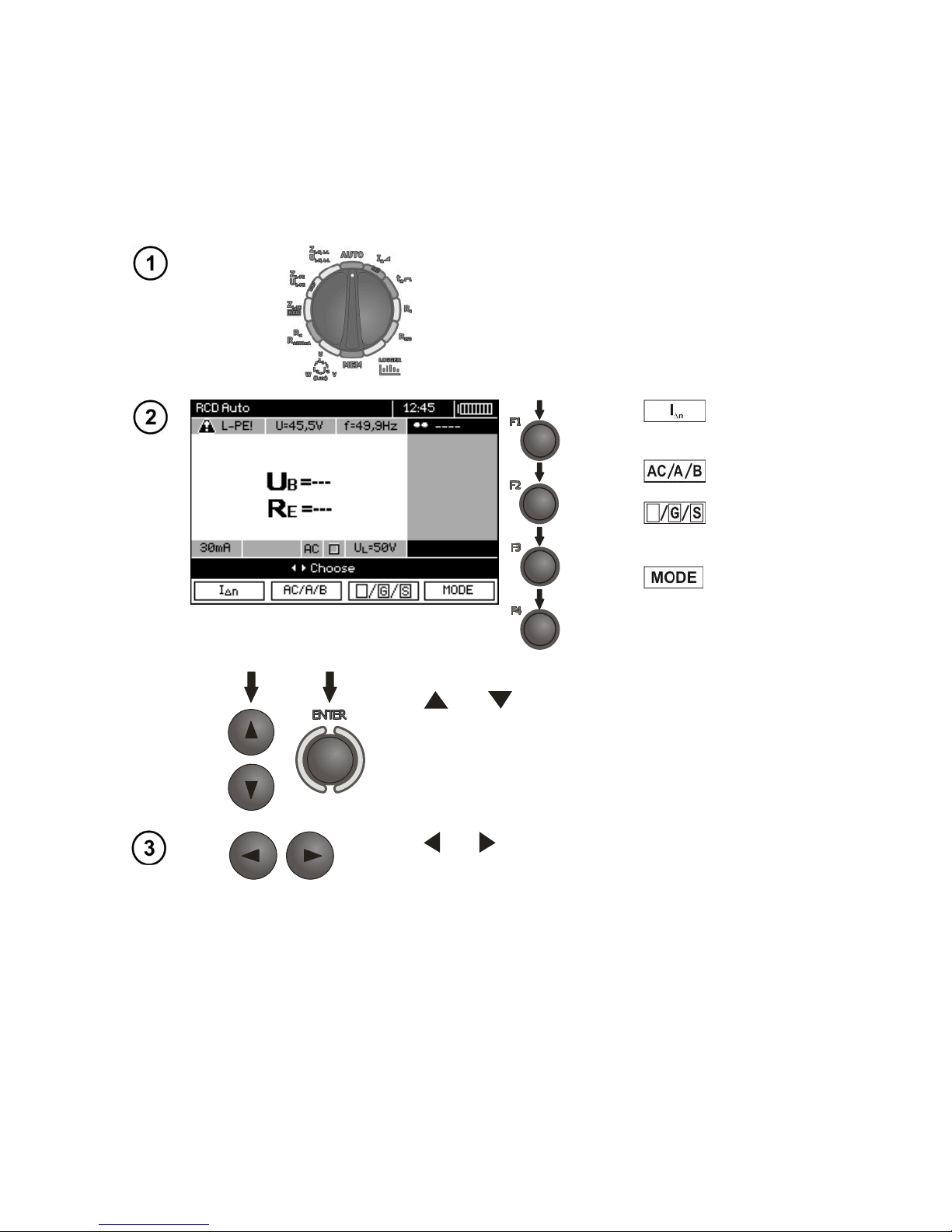
Set the rotary switch of function selection at
AUTO position.
Press F1 to enter In selection mode.
Press F2
to enter RCD
selection mode.
Press F3 to enter RCD
type selection mode.
Press F4 to enter the se-
lection of measurement mode
(RCD parameters for measurement).
Use and
to select a suitable position and press
ENTER to confirm.
Use and to enter the second group of parameters.
Page 56
OPERATING MANUAL MPI-530-IT version 1.06
54
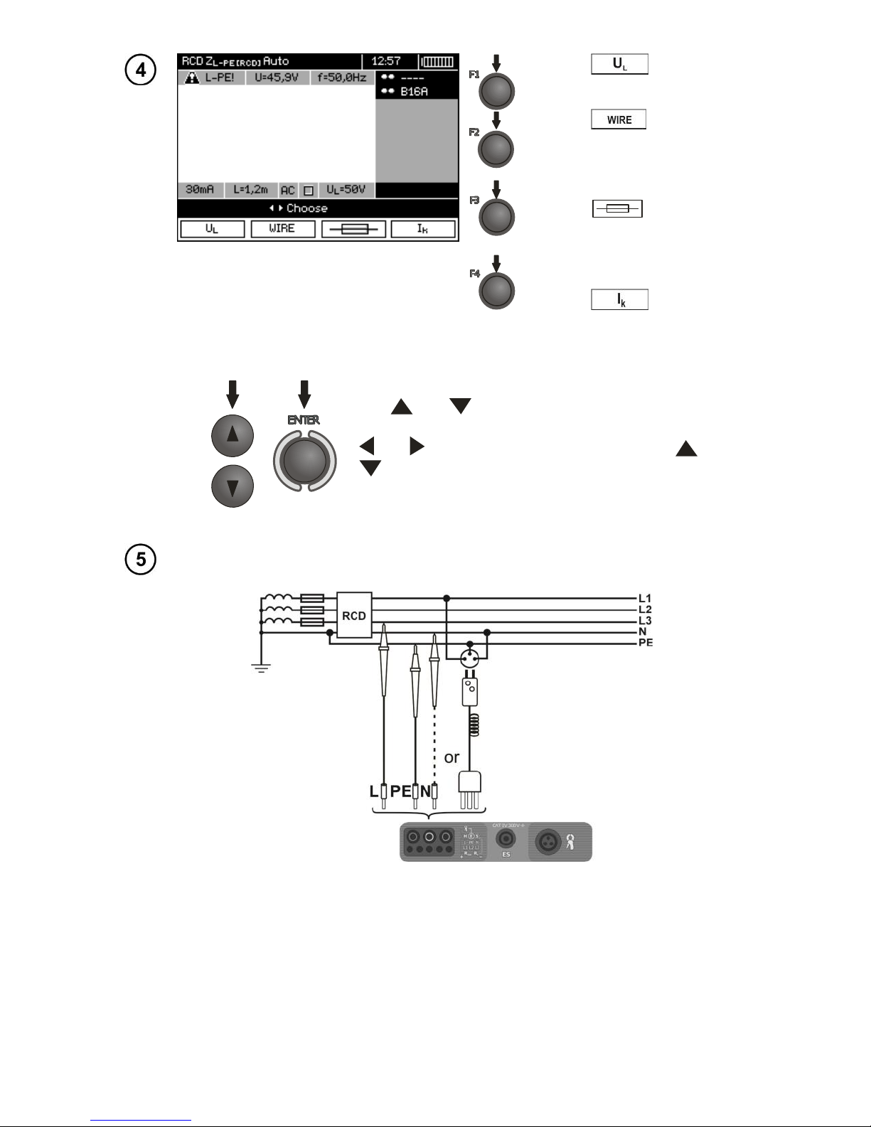
Press F1 to enter UL selection mode.
Press F2 to enter the selection of lead length "L" (for Z
L-PE
RCD measurement without WS
network plug).
Press F3 to enter the selection of overcurrent protection
(only for measurement of Z
L-PE
RCD).
Press F4 to enter the se-
lection of calculation method for Ik
(in relation to Un or U0 - (only for
measurement of Z
L-PE
RCD)).
Use and
to select desired position and press
ENTER to confirm. For selecting the security means, use
and to select the parameter and the use and
to select its value.
Measurement
Connect the meter to the installation according to the drawing.
Page 57
OPERATING MANUAL MPI-530-IT version 1.06
55
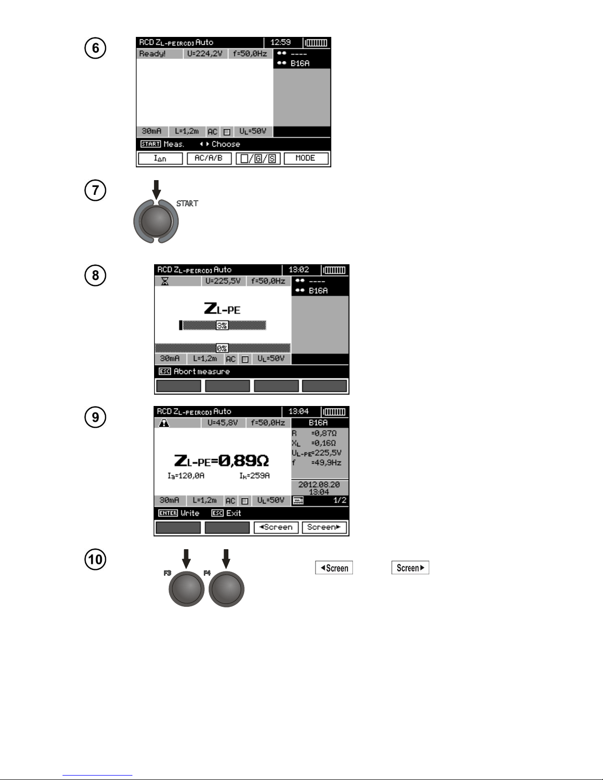
The meter is ready for measurement.
Value of network voltage and frequency can be read on the display.
Press START push-button to start the measurement. If such
measurements are selected that require triggering of RCD,
operator of the meter should be in the vicinity of RCD and
switch it on each time after it is triggered until the measurements are completed (a longer interruption may signify completion of the measurements).
Progress of measurement
process is shown by progress bars:
bottom - the whole cycle,
upper – Z
L-PE
RCD measurement and RCD parameters.
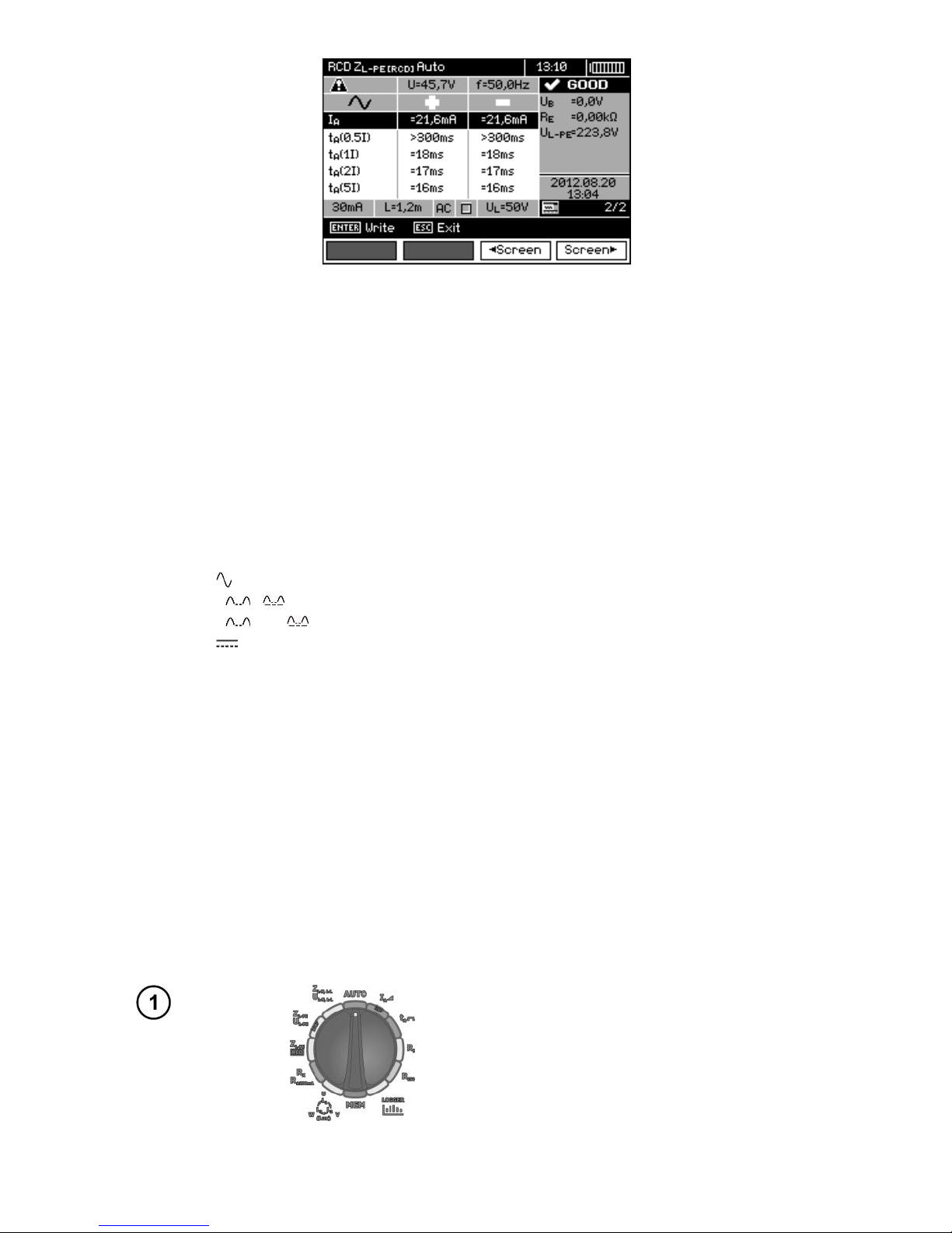
Read out the result.
Use F3 and F4 to change
displayed result groups.
Page 58
OPERATING MANUAL MPI-530-IT version 1.06
56
Note:
- The number of measured parameters depends on the settings entered in the main menu.
- UB and RE are always measured.
- Automatic measurement is interrupted in the following cases:
the switch was tripped during the measurement of UB RE or tA at the half value of IΔn,
the switch did not trip during other component measurements,
the value of safe voltage UL has been exceeded,
voltage was disconnected during one of the component measurements,
values RE and mains voltage did not allow to generate the required current value for one of com-
ponent measurements.
- The meter automatically skips the measurements impossible to perform, e.g. when the value of selected I
Δ
n
current and its multiplication factor exceed the testing range of the meter.
- Criteria for assessing the correctness of component results:
0.5*I
Δ
n
≤ IA ≤ 1*I
Δ
n
0.35*I
Δ
n
≤ IA i ≤ 2*I
Δ
n
for I
Δ
n
=10 mA
0.35*I
Δ
n
≤ IA and ≤ 1.4*I
Δ
n
for remaining I
Δ
n
0.5*I
Δ
n
≤ IA ≤ 2*I
Δ
n
tA at 0.5*I
Δ
n
→ rcd, for all types of RCD
tA at 1*I
Δ
n
≤ 300 ms for standard RCD's
tA at 2*I
Δ
n
≤ 150 ms for standard RCD's
tA at 5*I
Δ
n
≤ 40 ms for standard RCD's
130 ms ≤ tA at 1*I
Δ
n
≤ 500 ms for selective RCD's
60 ms ≤ tA at 2*I
Δ
n
≤ 200 ms for selective RCD's
50 ms ≤ tA at 5*I
Δ
n
≤ 150 ms for selective RCD's
10 ms ≤ tA at 1*I
Δ
n
≤ 300 ms for short-time delay RCD's
10 ms ≤ tA at 2*I
Δ
n
≤ 150 ms for short-time delay RCD's
10 ms ≤ tA at 5*I
Δ
n
≤ 40 ms for short-time delay RCD's
- Store the result in the memory (see sec. 4.2) or press ESC, and display only network voltage and
frequency.
- Remaining remarks and information are the same as for IA and Z
L-PE
measurement.
3.6.3.2 Standard mode
Settings
Set the rotary switch of function selection at
AUTO position.
Page 59
OPERATING MANUAL MPI-530-IT version 1.06
57
Press F1 to enter In selection mode.
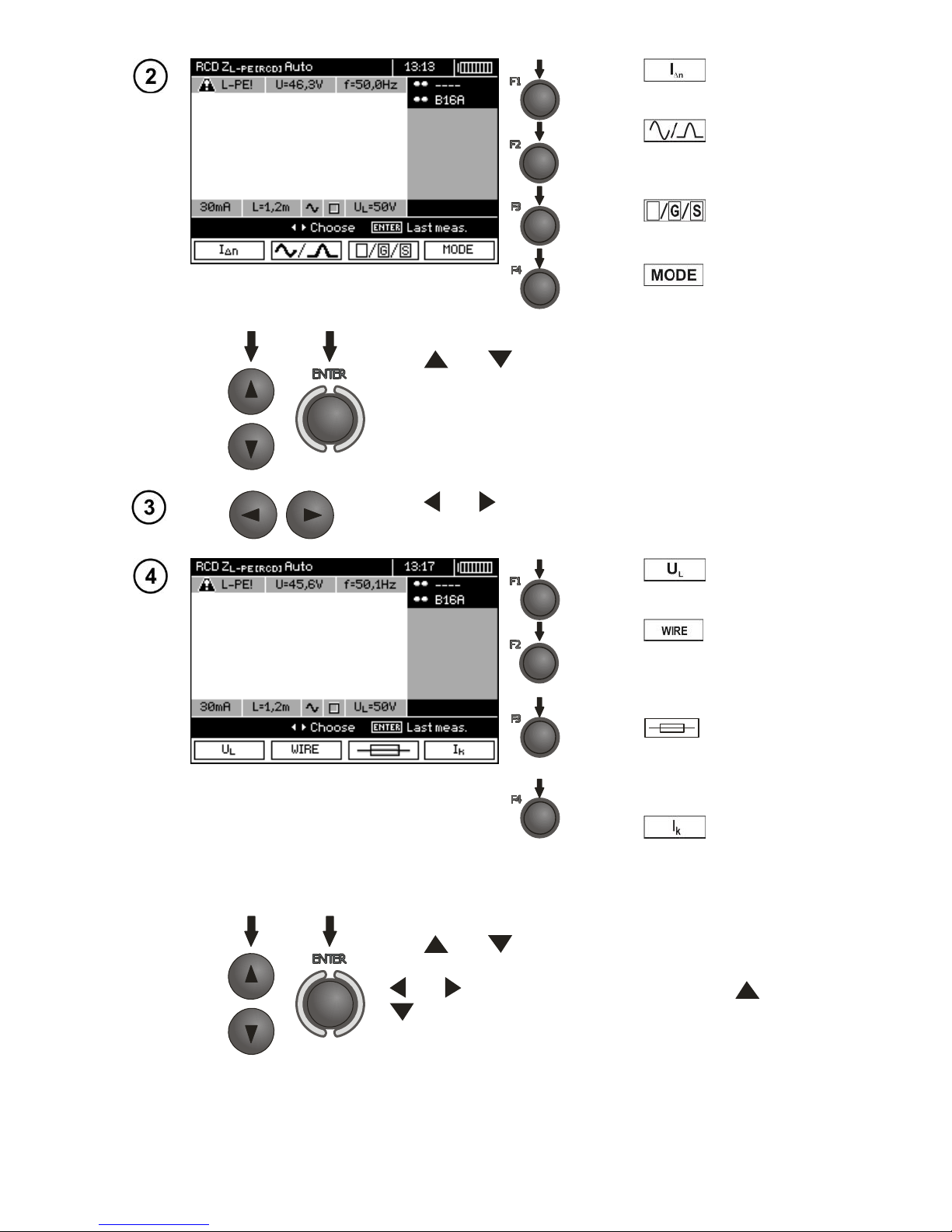
Press F2 to enter the selection mode for current waveform.
Press F3 to enter RCD
type selection mode.
Press F4 to enter the
measurement mode.
Use and
to select a suitable position and press
ENTER to confirm.
Use and to enter the second group of parameters.
Press F1 to enter UL selection mode.
Press F2 to enter the
selection of lead length "L" (for Z
L-
PE
RCD measurement without
WS network plug).
Press F3 to enter the se-
lection of overcurrent protection
(only for measurement of Z
L-PE
RCD).
Press F4
to enter the selection of calculation method for Ik
(in relation to Un or U0 - (only for
measurement of Z
L-PE
RCD)).
Use and
to select desired position and press
ENTER to confirm. For selecting the security means, use
and to select the parameter and the use and
to select its value.
Page 60
OPERATING MANUAL MPI-530-IT version 1.06
58
Measurement
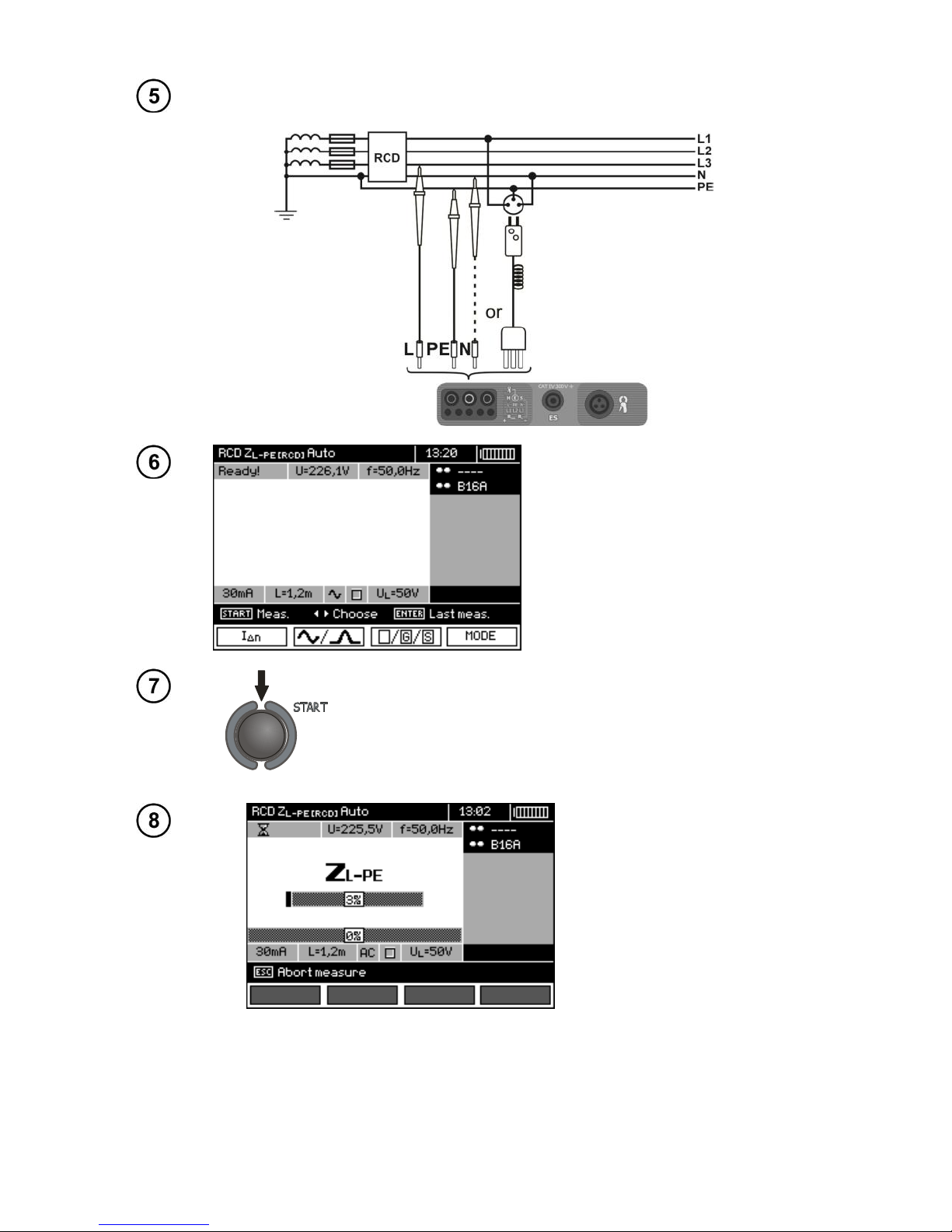
Connect the meter to the installation according to the drawing.
The meter is ready for measurement.
Value of network voltage and frequency can be read on the display.
Press START push-button to start the measurement. If such
measurements are selected that require triggering of RCD,
operator of the meter should be in the vicinity of RCD and
switch it on each time after it is triggered until the measurements are completed (a longer interruption may signify completion of the measurements).
Progress of measurement
process is shown by progress bars:
bottom - the whole cycle,
upper – Z
L-PE
RCD measurement and RCD parameters.
Page 61
OPERATING MANUAL MPI-530-IT version 1.06
59
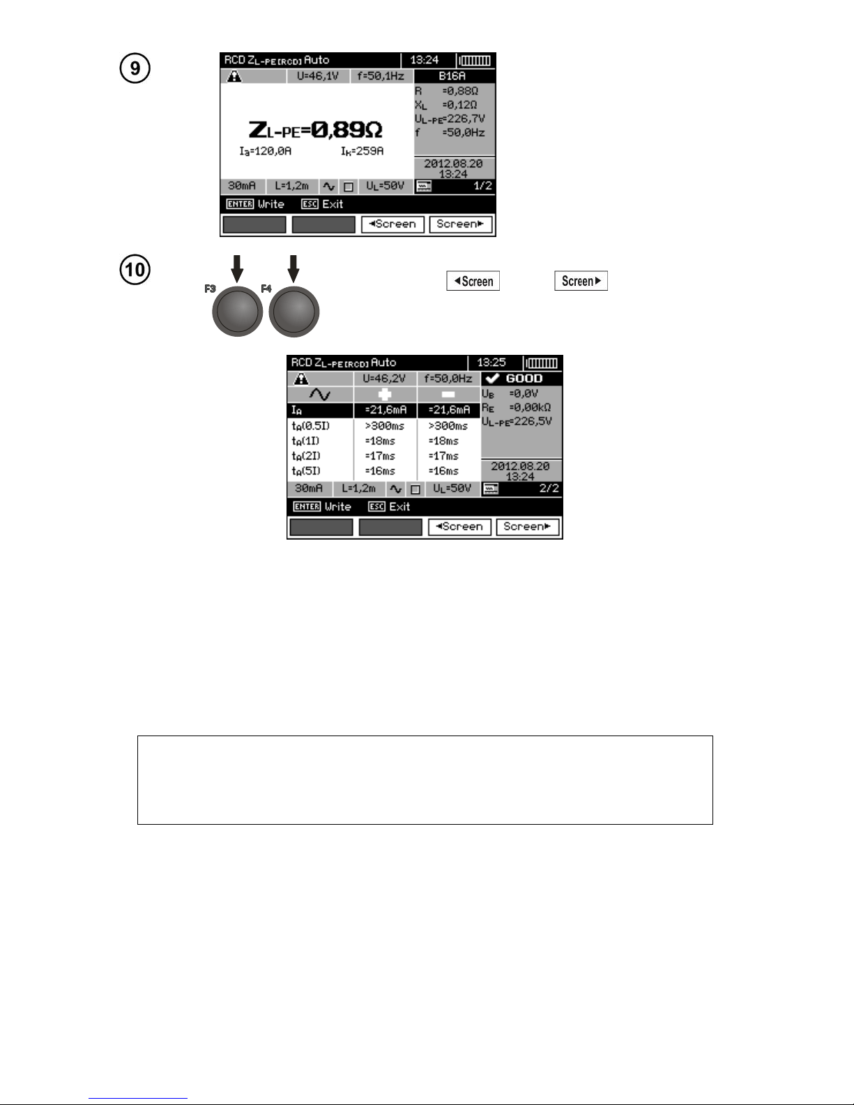
Read out the result.
Use F3 and F4 to change
displayed result groups.
Note:
- Remarks the same as in sec. 3.6.3.1.
3.6.4 Measurements in IT networks
Before making measurements, the proper network type (earthing system) shall be set in main menu
of the meter, see point 2.2.1.
WARNING:
When IT network type (IT system) is chosen, touch electrode on the meter is
disabled.
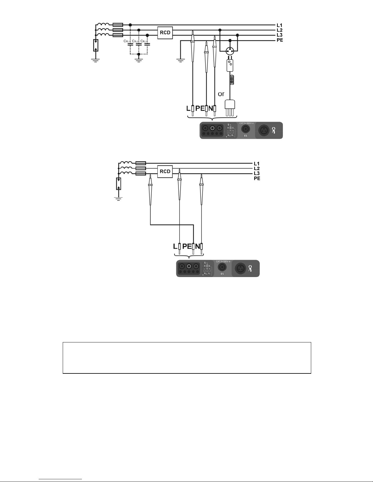
Connection of the meter to installation is show on the drawings below.
Page 62
OPERATING MANUAL MPI-530-IT version 1.06
60
a) Parasitic capacitance is used during the measurement.
b) If there is a possibility of connecting PE channel of the meter before the RCD.
The way of making measurements of RCD tripping time and current and automatic measurements is described in points 3.6.1, 3.6.2 and 3.6.3. Operating voltage range: 95 V … 440 V.
3.7 Measurement of insulation resistance
WARNING:
The tested object must not be live.
Page 63
OPERATING MANUAL MPI-530-IT version 1.06
61
3.7.1 Double-lead measurement
Settings
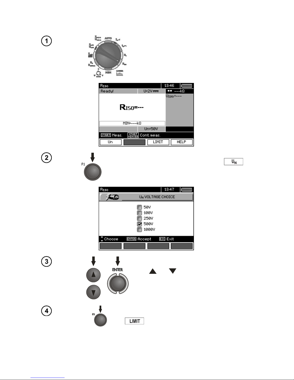
Set the rotary switch of function selection at R
ISO
position.
To change the measuring voltage press F1 .
Use and select the measuring voltage,
confirm by pressing ENTER.
In order to set the limit (minimum resistance), press F3
.
Page 64
OPERATING MANUAL MPI-530-IT version 1.06
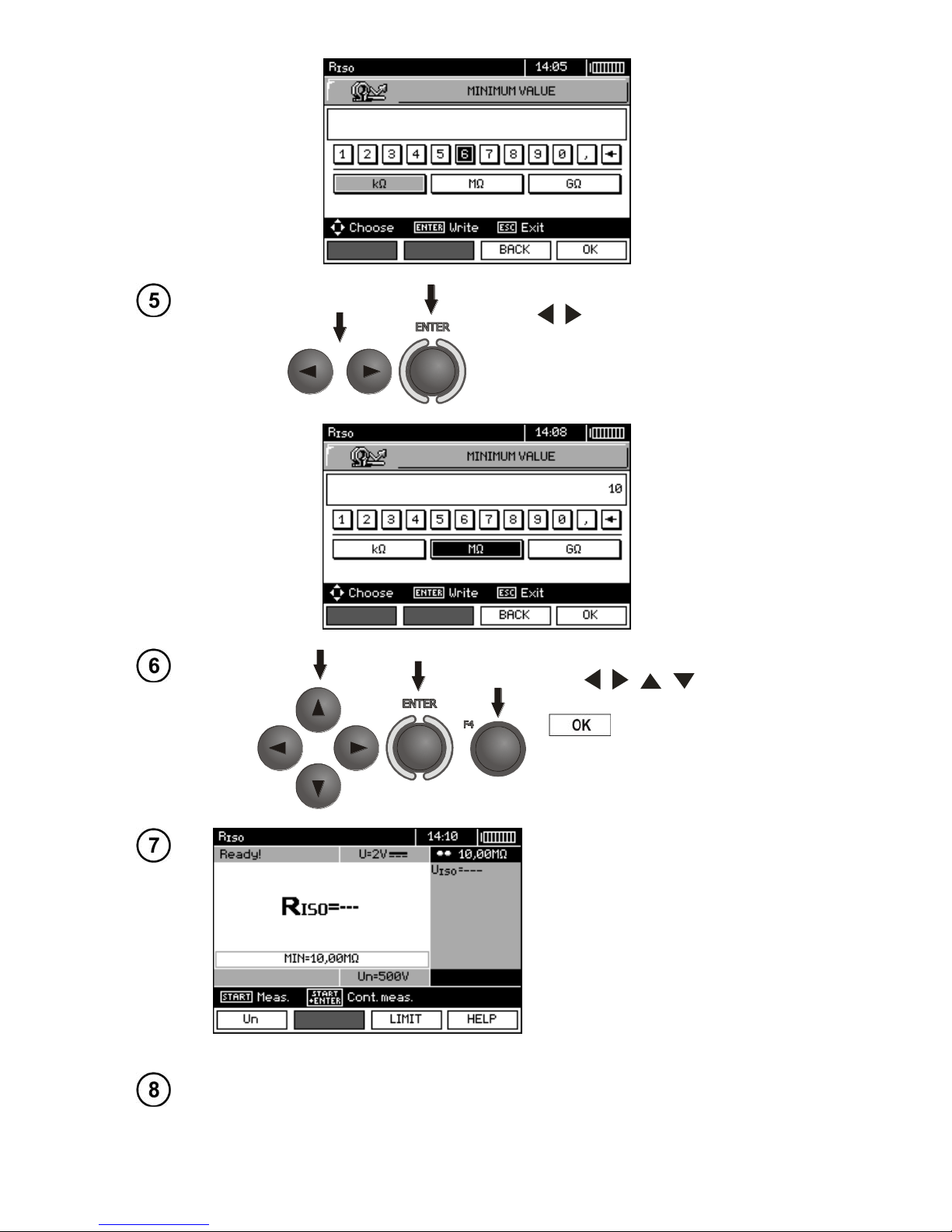
62
Use , and ENTER to enter the resistance value.
Use , , , and ENTER to
select unit, confirm by pressing F4
.
The meter is ready for measurement.
Value of interference voltage can
be read on the display.
Measurement
Connect test leads according to the drawing.
Page 65
OPERATING MANUAL MPI-530-IT version 1.06
63
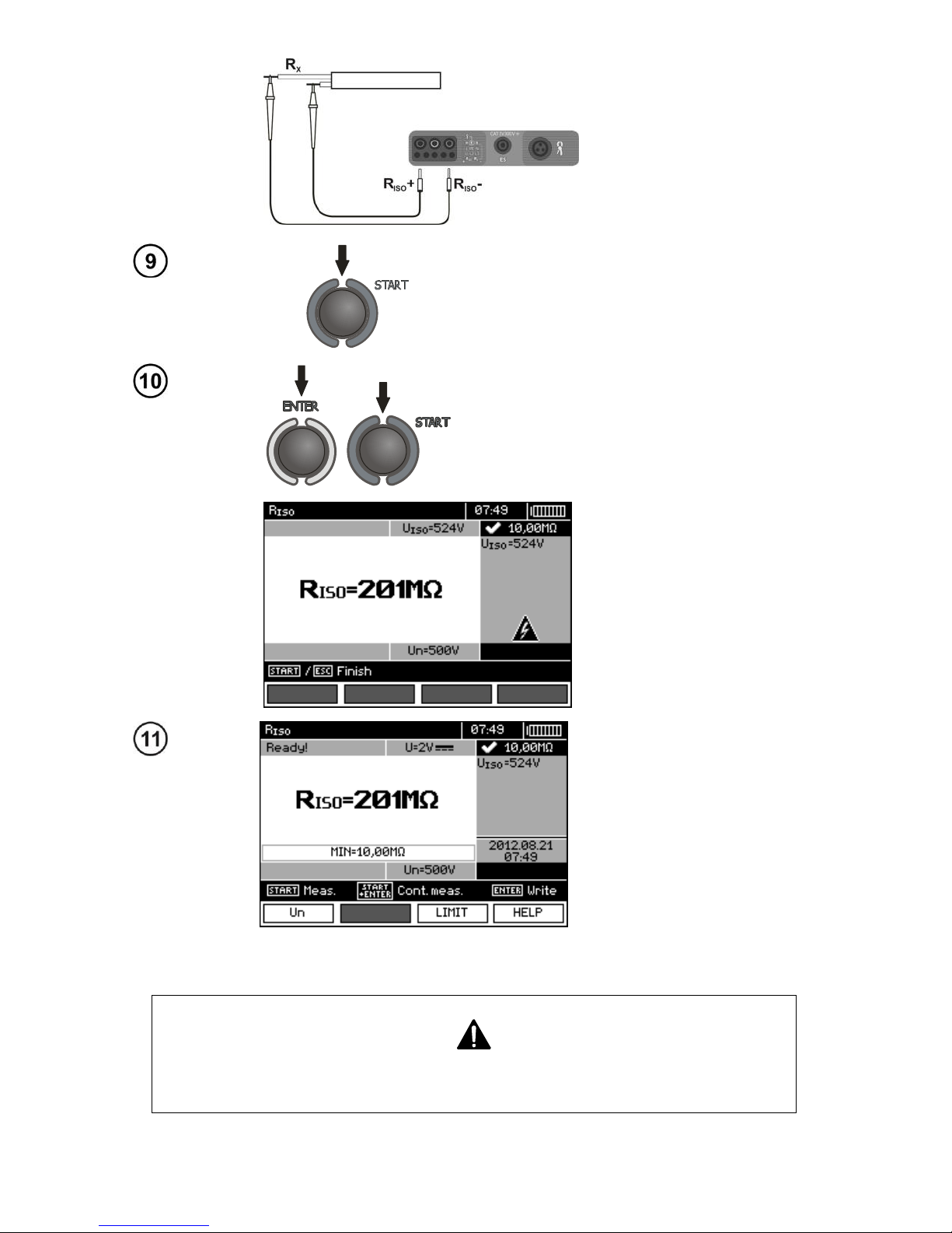
Press and hold START push-button.
Measurement is performed continuously
when the push-button is held in the pressed
position.
In order to maintain the measurement,
press ENTER push-button while holding
START push-button in the pressed position. In order to interrupt the mesaurement,
press START.
View of the screen during
measurement performed
with the use of ENTER-
push-button.
Read out the result.
Note:
During measurements of insulation resistance, dangerous voltage up to 1 kV
occurs at the ends of test leads of MPI-530-IT.
Page 66
OPERATING MANUAL MPI-530-IT version 1.06
64
It is forbidden to disconnect test leads and to change the position of the function switch before completion of measurement. Failure to obey the above instruction will lead to high voltage electric shock and make it impossible to discharge the tested object.
- The meter emits a continuous audio signal until test voltage reaches 90 % of the preset value (and
also when 110 % of the preset value is exceeded).
- After completion of measurement, the capacitance of the object tested is discharged by shorting
R
ISO
+ and R
ISO
- terminals with resistance of 100 k.
Additional information displayed by the meter
Test voltage is present on terminals of the meter.
NOISE!
Interference voltage occurs on the tested object. Measurement is possible but may be burdened with additional
uncertainty.
LIMIT I!
Current limit tripped. The symbol displayed during the
measurement is accompanied by a continuous beep. If this
symbol is displayed after the measurement, it means that
the measurement result was obtained during operation
with a current limiting device.
3.7.2 Measurements by means of leads with UNI-Schuko outlet plug (WS-03
and WS-04)
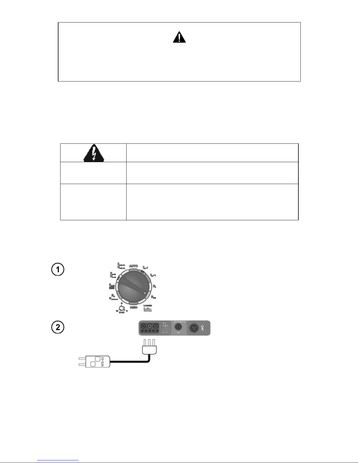
Settings
Set the rotary switch of function selection at
R
ISO
position.
Connect WS-03 lead or WS-04
lead with UNI-Schuko outlet plug.
The meter detects this fact automatically and changes the appearance of the screen.
Page 67

OPERATING MANUAL MPI-530-IT version 1.06
65
Press F1 push-button
and move to selection of test
voltage UN.
Press F2 to enter the
selection of lead sequence: L,
PE, N or N, PE, L or L+N, PE.
Press F3 push-button
and move to selection of a single measurement time.
Use and
to select desired position and press
ENTER to confirm.
Note: If it is known that L and N leads in the socket are
exchanged, after pressing F2 it is possible to select the
sequence of (N)(PE)(L), in order to ensure that the meter
provides correct results of measurements.
Note: (L+N)(PE) mode causes the shorting of L and N
wires in the tested socket.
Use and to enter the second group of parameters.
Press F3
to set the
minimal resistance.
Use , and ENTER to enter the resistance value.
Page 68
OPERATING MANUAL MPI-530-IT version 1.06
66
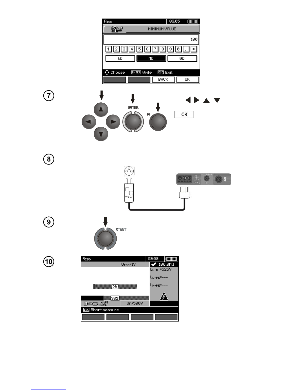
Use , , , and ENTER to
select unit, confirm by pressing F4
.
Measurement
Connect WS-03 or WS-04 lead to the socket tested.
Press START to start measurement. If any of the
voltages exceeds allowable voltage value (50 V),
Voltage on object! message is displayed and the
measurement is blocked.
View of the screen during
measurement.
The display shows the
symbol of the resistance
being measured and the
progress bar of this measurement.
The bottom progress bar
shows % of progress of total measurement.
Page 69
OPERATING MANUAL MPI-530-IT version 1.06
67
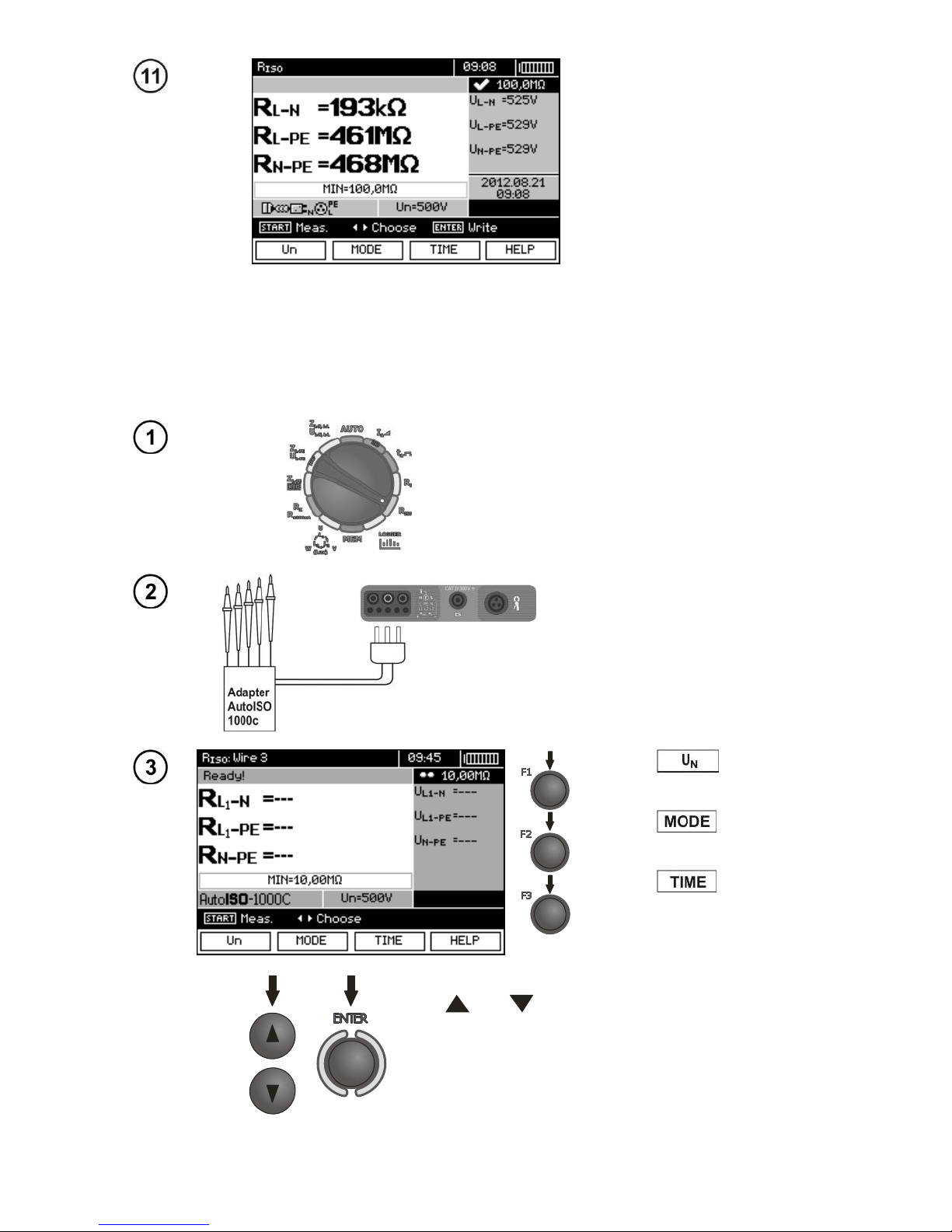
Read out the results.
Note:
- Remarks and messages are the same as in point 3.7.1.
3.7.3 Measurements with AutoISO-1000c adapter
Settings
Set the rotary switch of function selection at
R
ISO
position.
Connect AutoISO-1000c adapter.
The meter detects this fact automatically and changes the appearance of the screen.
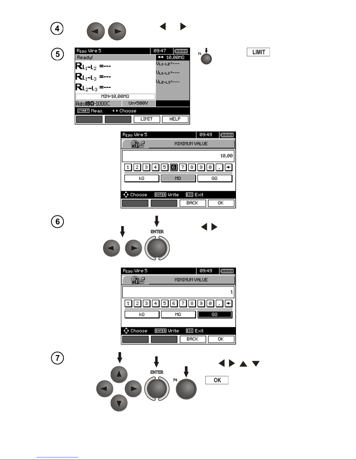
Press F1 push-button
and move to selection of test
voltage UN.
Press F2 push-button
and move to selection of lead
type (3-, 4- or 5-wire lead).
Press F3 push-button
and move to selection of a single measurement time.
Use and
to select desired position and press
ENTER to confirm.
Page 70
OPERATING MANUAL MPI-530-IT version 1.06
68
Use and to enter the second group of parameters.
Press F3 to set the
minimal resistance.
Use , and ENTER to enter the resistance value.
Use , , , and ENTER to
select unit, confirm by pressing F4
.
Page 71
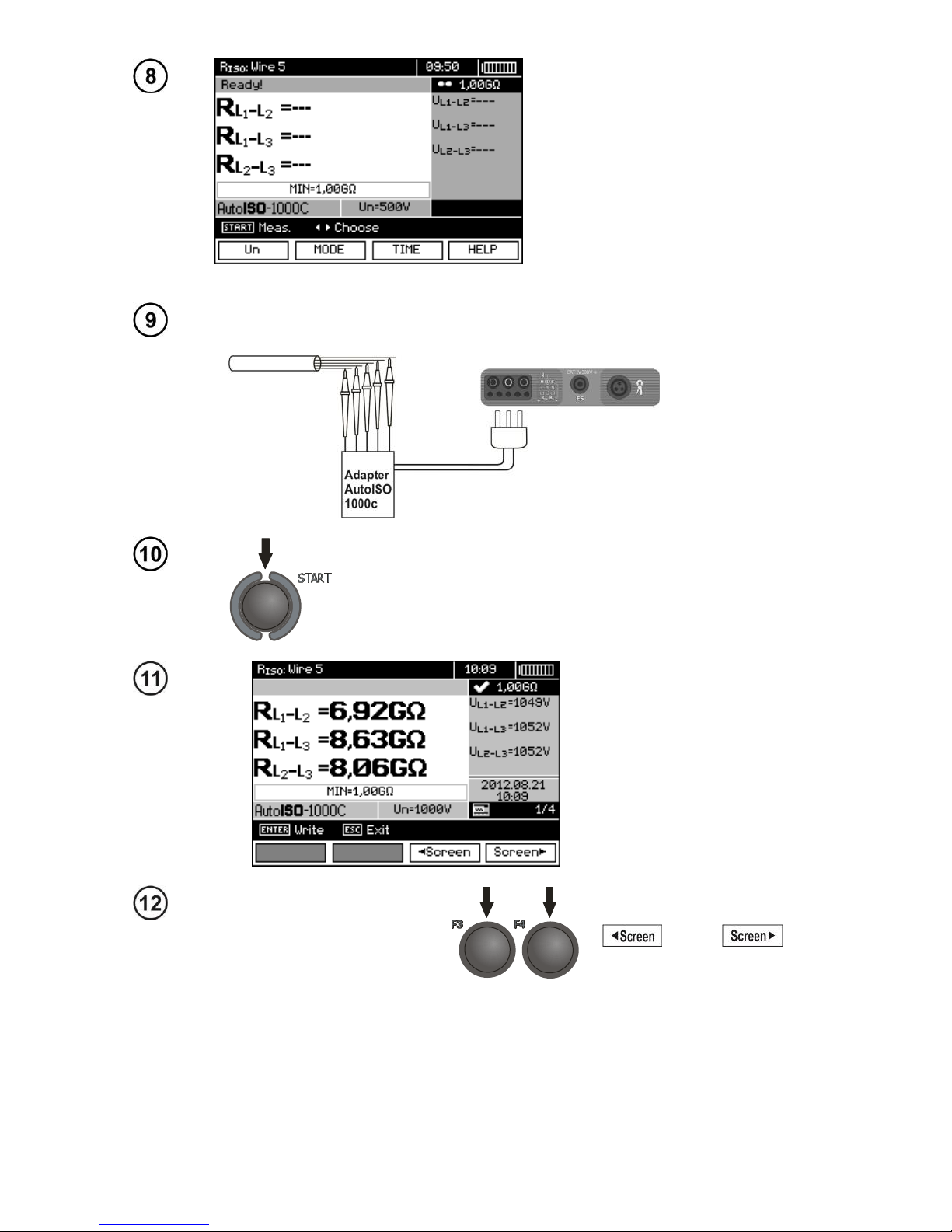
OPERATING MANUAL MPI-530-IT version 1.06
69
The meter is ready for measurement.
Value of interference voltage can
be read on the display.
Measurement
Connect AutoISO-1000c adapter to the lead tested.
Press START to start measurement. First, the voltage on
individual wire pairs is checked.
If any of the voltages exceeds allowable values, the symbol of this voltage is displayed with "!" (e.g. U
N-PE
!) and
the measurement is interrupted.
Read out the results.
Groups of results displayed
are changed by means of F3
and F4
push-buttons.
Page 72
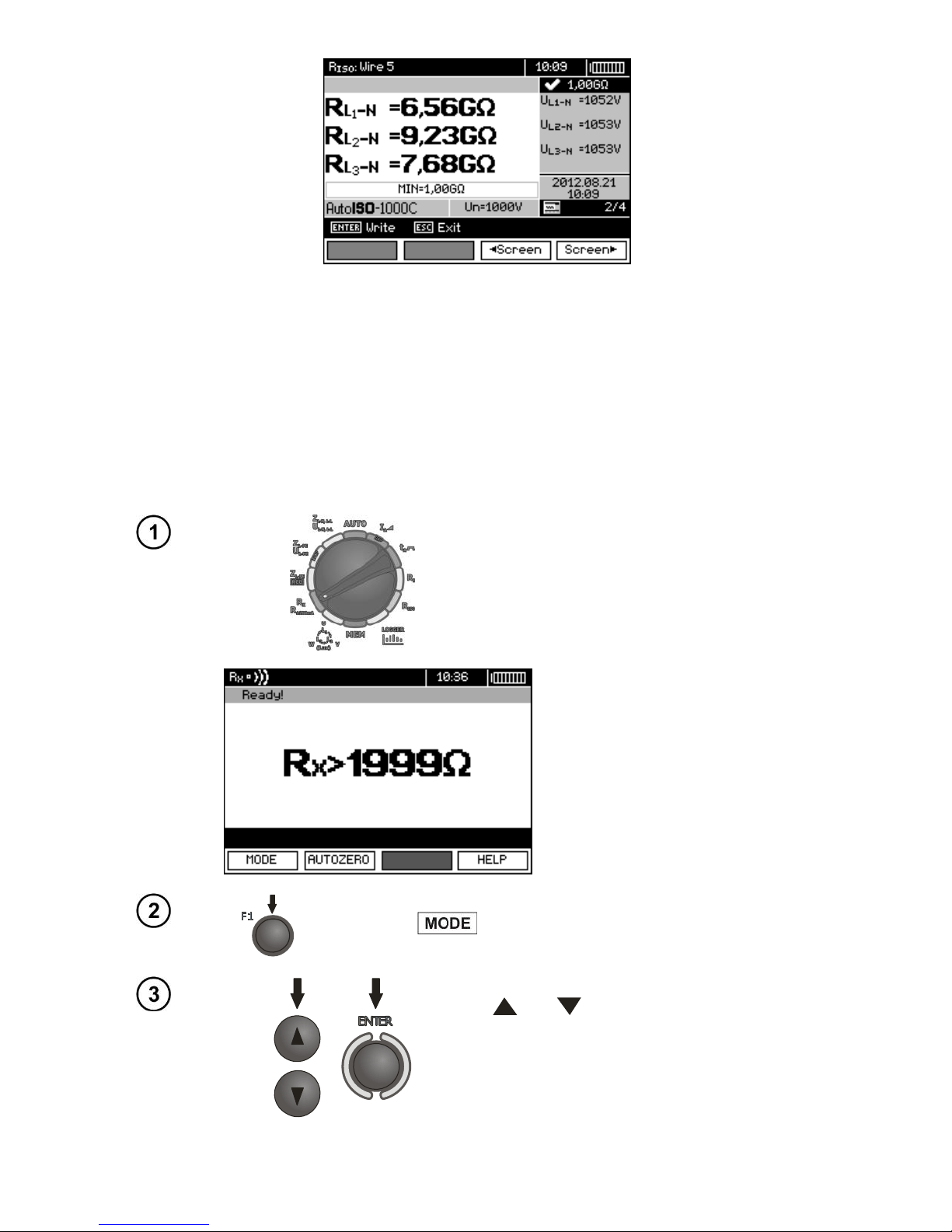
OPERATING MANUAL MPI-530-IT version 1.06
70
Note:
- Remarks and messages are the same as in point 3.7.1.
3.8 Low-voltage measurement of resistance
3.8.1 Measurement of resistance of protective conductors and equipotential bonding with ±200 mA current
Settings
Set the rotary switch of function selection at
RX R
±200mA
position.
Press F1 and move to the selection of the measurement
mode.
Use and to select R
CONT
±200mA, con-
firm by pressing ENTER.
Page 73
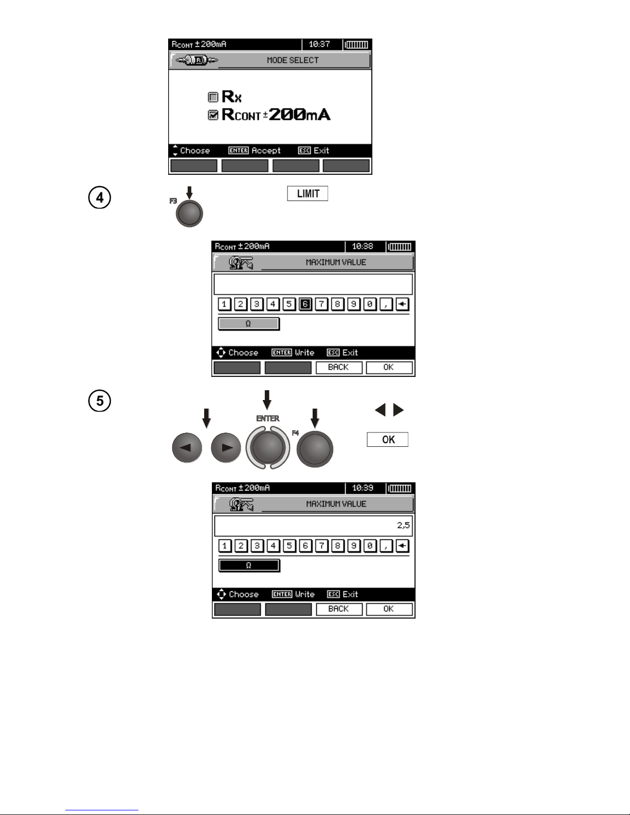
OPERATING MANUAL MPI-530-IT version 1.06
71
Press F3 to set the maximum resistance.
Use , and ENTER to enter the
resistance value. Confirm by pressing
F4 .
Page 74
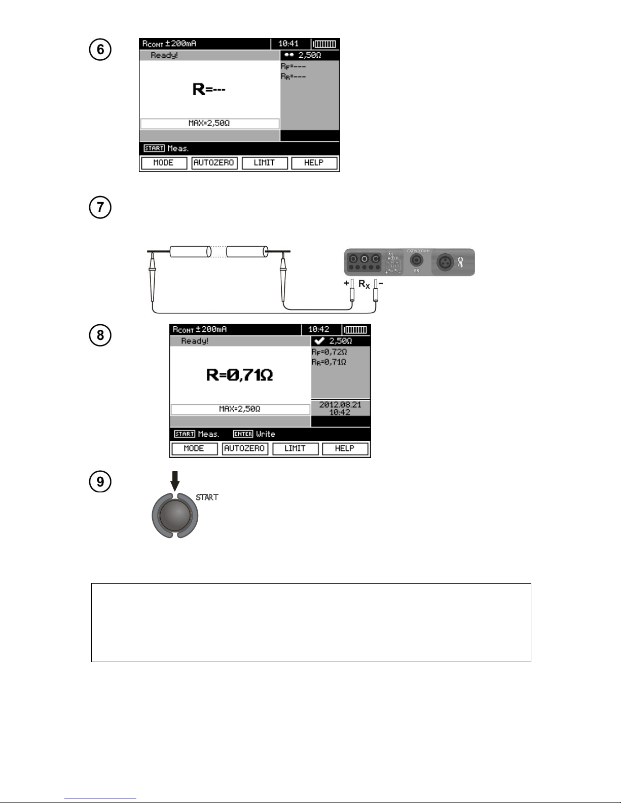
OPERATING MANUAL MPI-530-IT version 1.06
72
The meter is ready for measurement.
Measurement
Connect the meter to the tested object.
Measurement starts automatically.
Read out the results.
In order to start the next measurement without disconnecting test leads form the object, press START.
Note:
ATTENTION!
When “Voltage on object” message is displayed, the object tested is live. The
measurement is blocked. The meter must be immediately disconnected from the
object.
Page 75
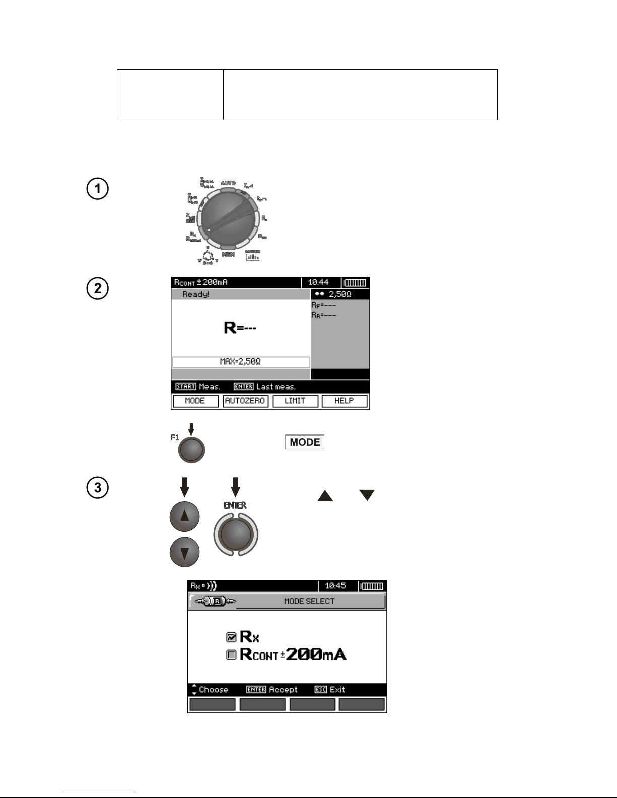
OPERATING MANUAL MPI-530-IT version 1.06
73
Additional information displayed by the meter
NOISE!
Interference voltage occurs on the tested object. The
measurement is possible however it will be burdened
with additional uncertainty that is specified in specifications.
3.8.2 Measurement of resistance
Settings
Set the rotary switch of function selection at RX
R
±200 mA
position.
Press F1
push-button and move to selection of
measurement mode.
Use and to select RX, confirm by pressing ENTER.
Page 76
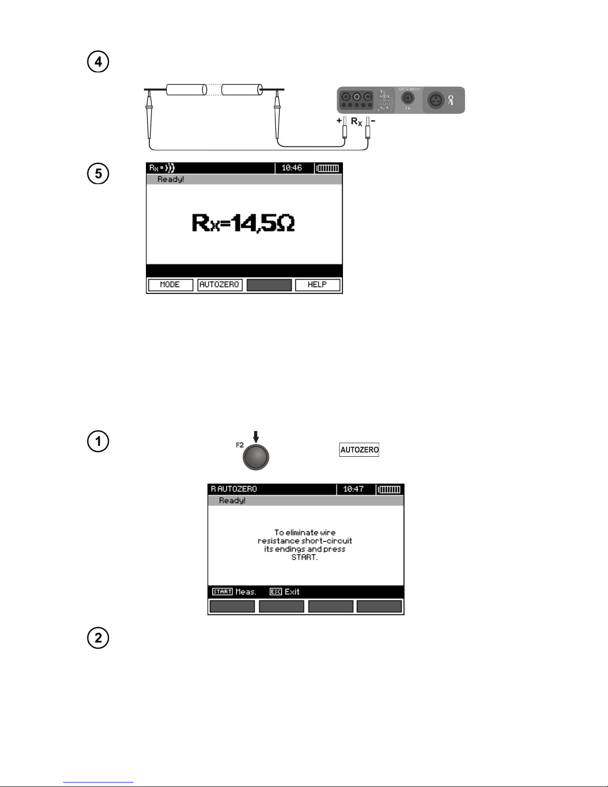
OPERATING MANUAL MPI-530-IT version 1.06
74
Measurement
Connect the meter to the tested object.
Read out the result.
Note:
- Remarks and messages are the same as in 3.8.1.
3.8.3 Compensation of test leads resistance
In order to eliminate the impact of the resistance of test leads on measurement result, the com-
pensation (autozeroing) of resistance may be performed. For this purpose, RX i R
±200mA
functions
have AUTOZERO sub-function.
Press F2 .
Follow the instructions displayed on the screen.
Page 77
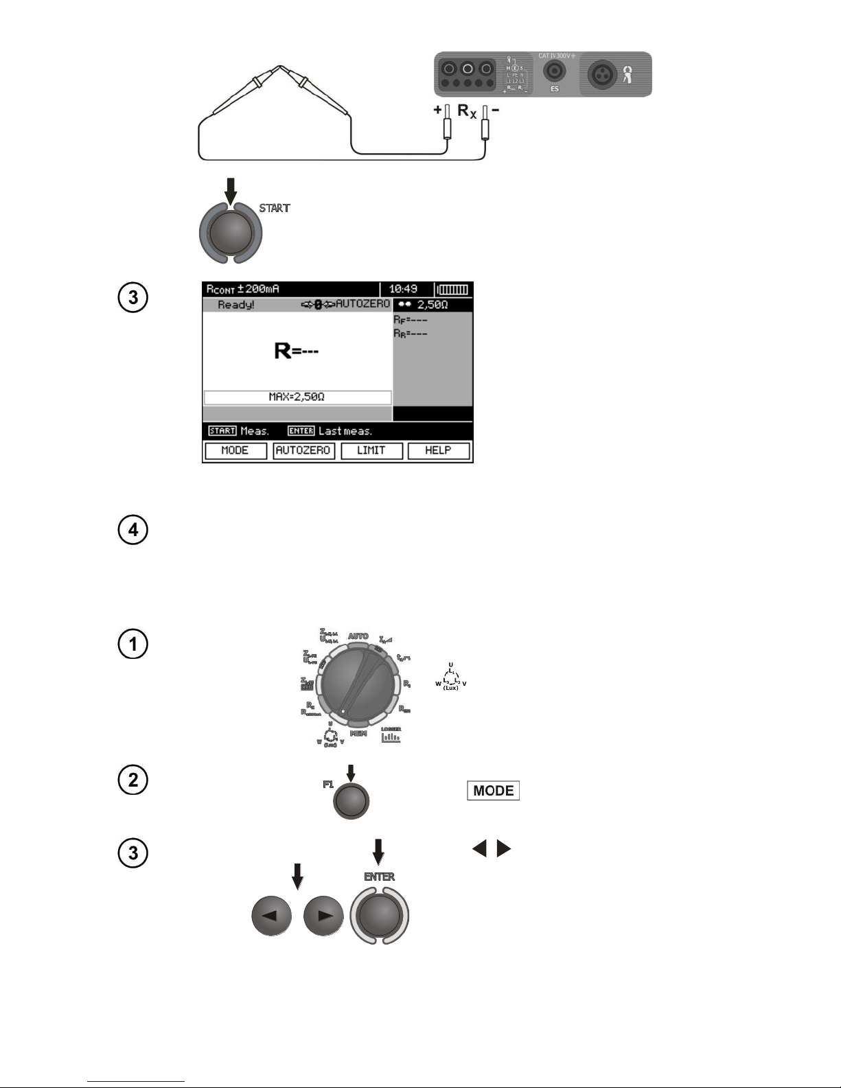
OPERATING MANUAL MPI-530-IT version 1.06
75
AUTOZERO message appears that confirms completion of test leads calibration.
In order to remove the compensation of the leads resistance (return to default
calibration), perform the above-mentioned activities with test leads open.
3.9 Checking sequence of phases
Settings
Set the rotary switch of function selection at
.
Press F1 .
Use , to select PHASE SEQUENCE,
confirm by pressing ENTER.
Page 78
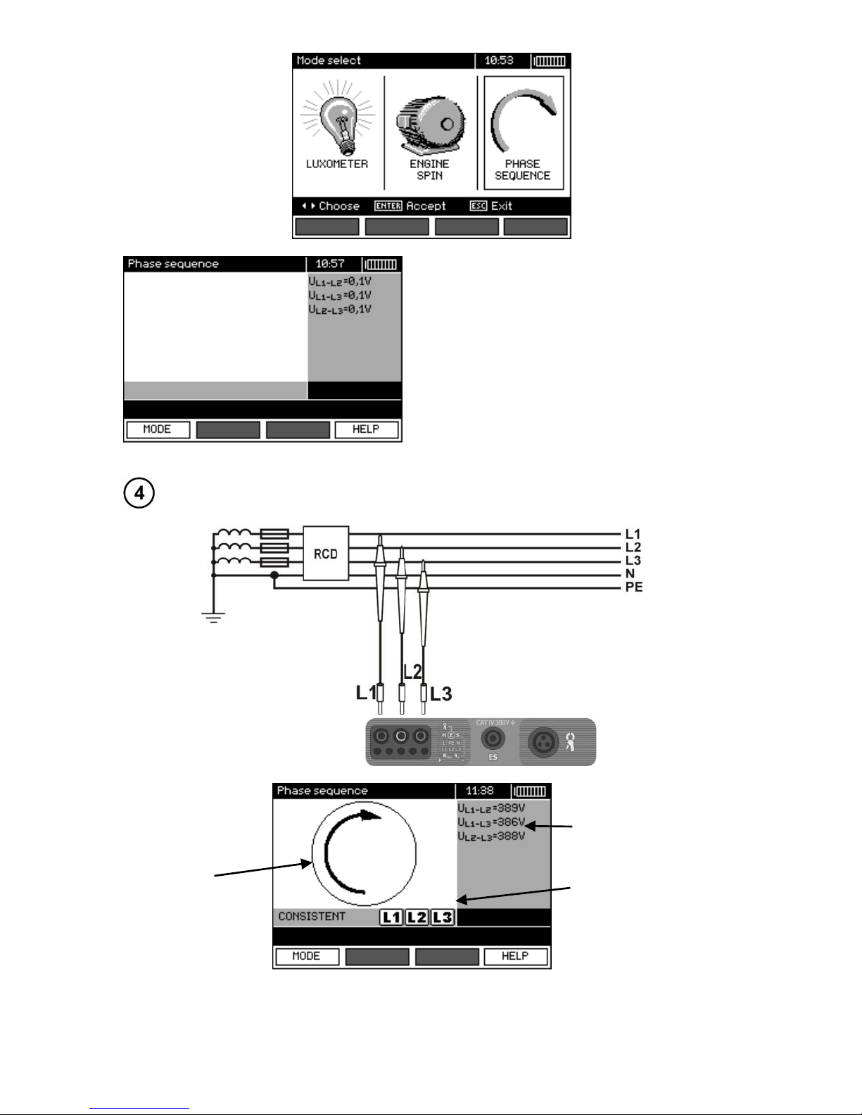
OPERATING MANUAL MPI-530-IT version 1.06
76
The meter ready for testing.
Measurement
Connect the meter to the installation according to the drawing.
The arrow rotates
clockwise:
correct sequence of
phases,
arrow rotates counter-clockwise: the
phase sequence is
incorrect.
Phase-to-phase
voltages.
Signalling
the presence
of individual
phases.
Page 79
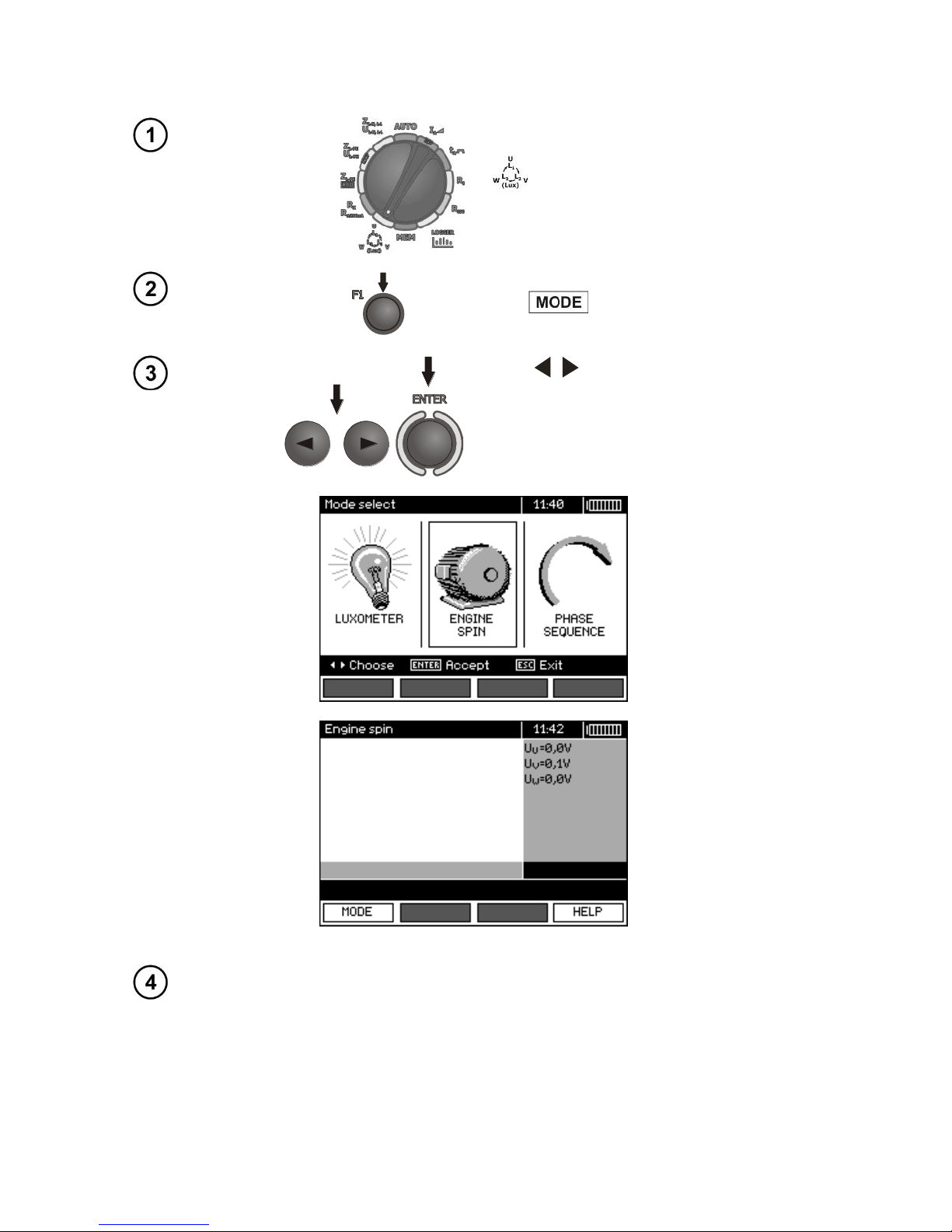
OPERATING MANUAL MPI-530-IT version 1.06
77
3.10 Checking the motor rotation direction
Settings
Set the rotary switch of function selection at
.
Press F1 .
Use , to select MOTOR ROTATION,
confirm by pressing ENTER.
Measurement
Connect the meter to the motor according to the drawing.
Page 80
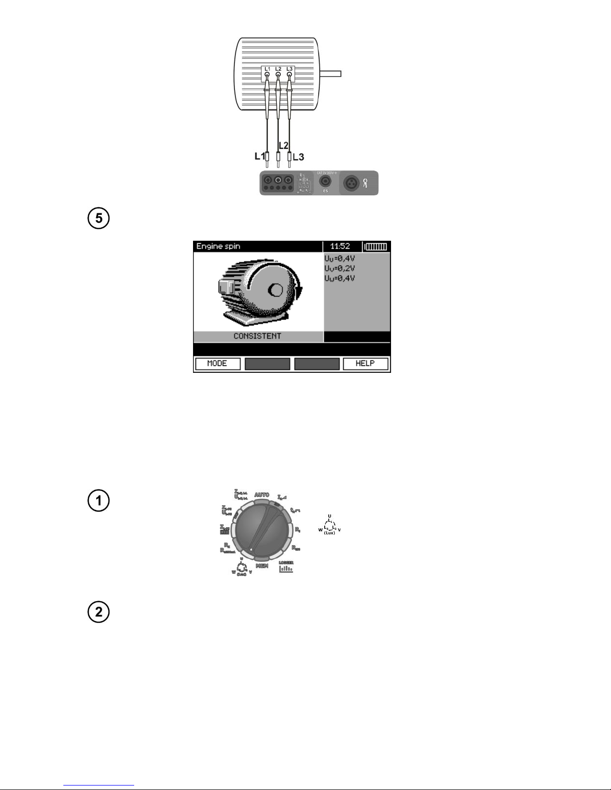
OPERATING MANUAL MPI-530-IT version 1.06
78
Vigorously rotate the motor shaft in the desired direction.
The arrow rotates
clockwise:
when L1, L2, L3
motor terminals are
connected to L1,
L2, L3 phases (respectively), the motor will rotate in the
same direction as it
was rotated during
the test.
The arrow rotates
counter-clockwise:
when L1, L2, L3 motor
terminals are connected
to L1, L2, L3 phases (respectively), the motor will
rotate in the opposite direction to the rotations
during the test.
Note:
- When disconnected test leads are moved, they may induce voltages that result in indicating the direction of rotation. Do not move the test leads during the test.
3.11 Light measurements
Settings
Set the rotary switch of function selection at
.
Measurement
Connect the optical probe. Instrument enters the light measurement mode.
Page 81
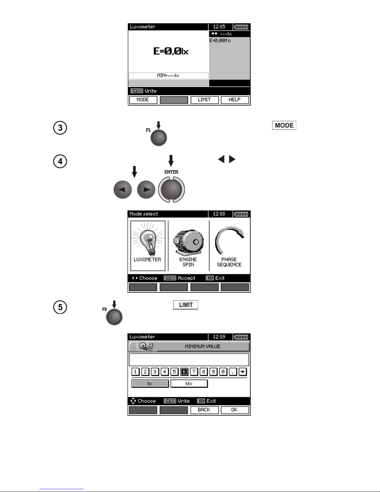
OPERATING MANUAL MPI-530-IT version 1.06
79
Settings
Connecting the probe after F1 is
pressed...
...use , to select LUXMETER, confirm by pressing ENTER.
Press F3 to set the minimum illumination.
Page 82
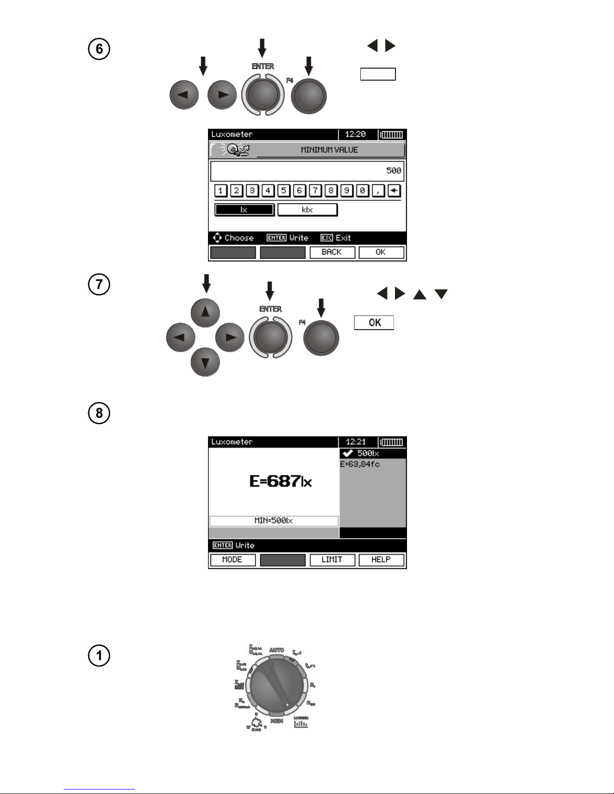
OPERATING MANUAL MPI-530-IT version 1.06
80
Use , and ENTER to enter the
value of lighting. Confirm by pressing
F4
OK
.
Use , , , and ENTER to
select unit. Confirm by pressing F4
.
Measurement
After correct location of the probe - read out the result.
3.12 Recorder. Measurement and recording of current, voltage,
cosφ, PF factor, harmonics and THD
Settings
Set the rotary switch of function selection at LOGGER position.
Page 83
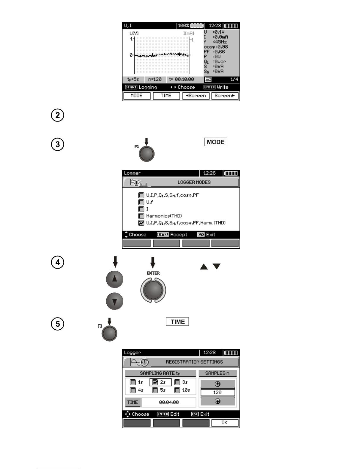
OPERATING MANUAL MPI-530-IT version 1.06
81
In MENU (section 2.2.3), select network nominal voltage and frequency.
This voltage is used for calculating the deviation of measured voltage [in
%] from selected nominal value.
Press F1 , to select the parameters to
be recorded.
Use , to select the parameter set for
recording, press ENTER to approve.
Press F2 , to set the sampling time and number of
samples.
Page 84
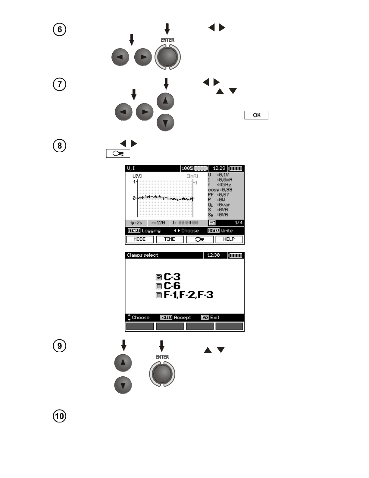
OPERATING MANUAL MPI-530-IT version 1.06
82
Use , and ENTER to select the
sampling period.
Use , to select the number of samples,
then use , to set the number of sam-
ples - the recording time is calculated basing
on the sampling time and the number of
samples. Press F4
to enter the
measurement screen.
Use , to change the appearance of the setting bar. Press F3
to enter the selection of clamp type.
Use , to select the type of clamps,
press ENTER to approve.
Measurement
Connect the device according to the drawing (example of measurement
on a motor).
Page 85
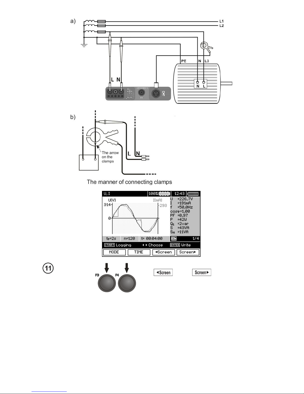
OPERATING MANUAL MPI-530-IT version 1.06
83
Groups of results displayed are changed by means
of F3 and F4 push-buttons.
Page 86
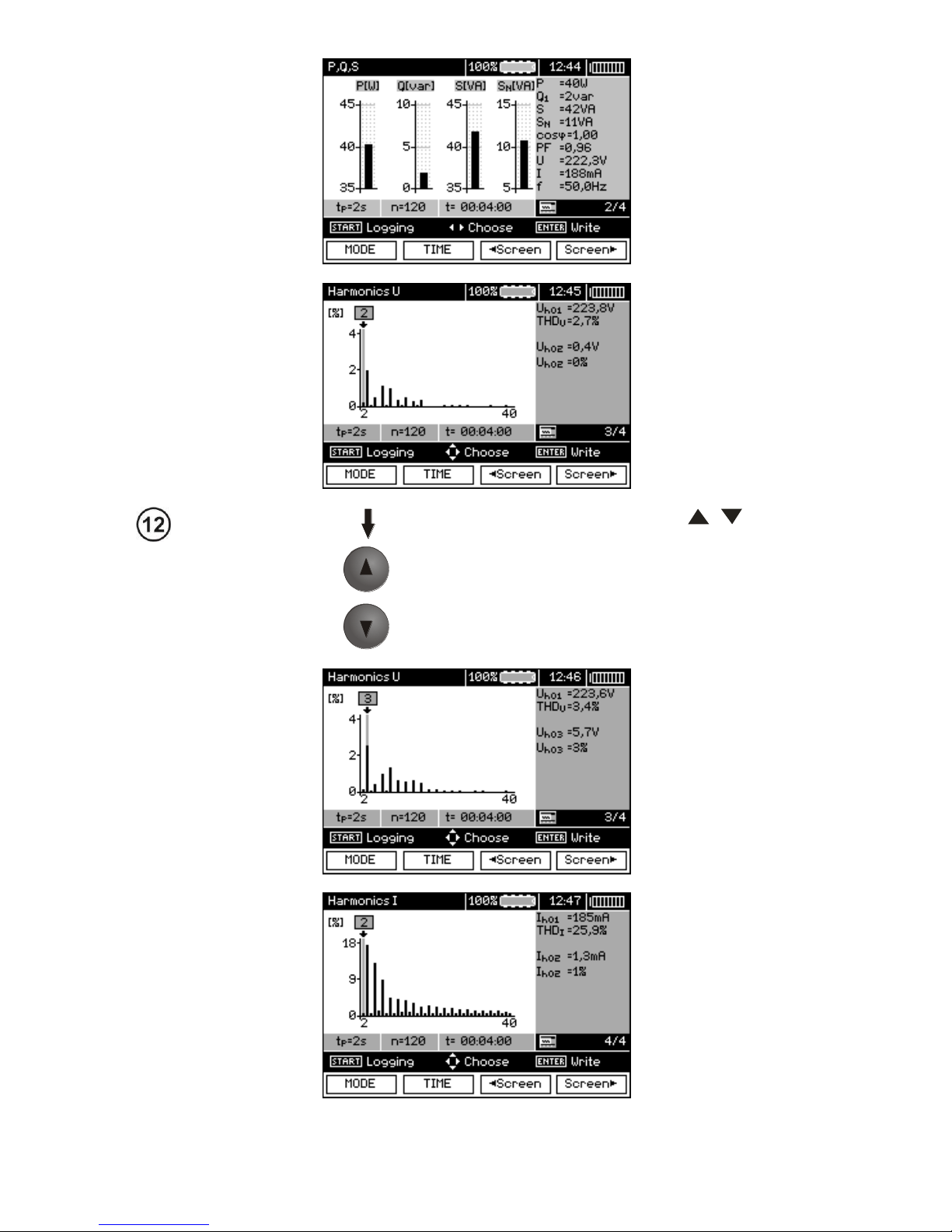
OPERATING MANUAL MPI-530-IT version 1.06
84
When displaying harmonics, use , to select
the number of the harmonic, with the value displayed on the right side of the screen.
Page 87
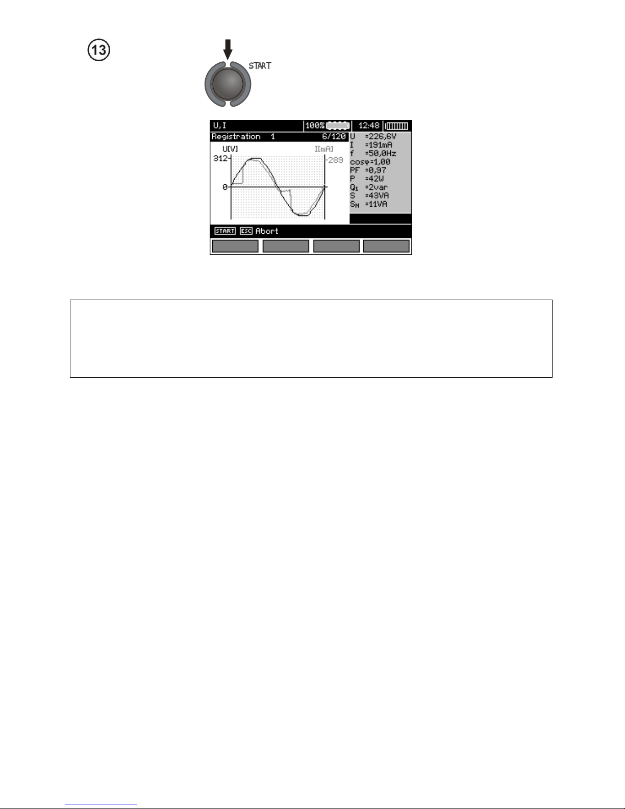
OPERATING MANUAL MPI-530-IT version 1.06
85
Press START to start recording.
Note:
Note:
In order to avoid ambiguity in the calculating power values, attach clamps with their arrows indicating the point of connecting L terminal of the meter to the tested object (Figure
b)).
- During recording only one screen is displayed - the one that was displayed at the start of recording.
- In order to save energy, the meter displays data for 30 seconds from activating it, then it enters energy saving mode (the screen is blanked, LED flashes with 1-sec intervals). Pressing any key activates the device from the standby mode.
4 Memory of measurement results
4.1 Structure of the Memory
The memory for test results has a tree-like structure (see figure below). The user has the ability
to record data for ten clients. Each client may create max. 999 objects, which may store up to three
levels of sub-objects, 999 sub-objects for each level. Each subject, and sub-object may store up to
999 measurements.
The whole structure is limited by the size of memory. The memory allows for simultaneous recording of 10 full descriptions of customers, and a minimum of: measurement sets for 10000 measuring points and 10000 names of these points, 999 names for objects, 999 descriptions of sub-objects
and remember the layout created for these objects. Additionally the memory has a space for the list
of names (selection lists) extended up to 99 entries.
Page 88
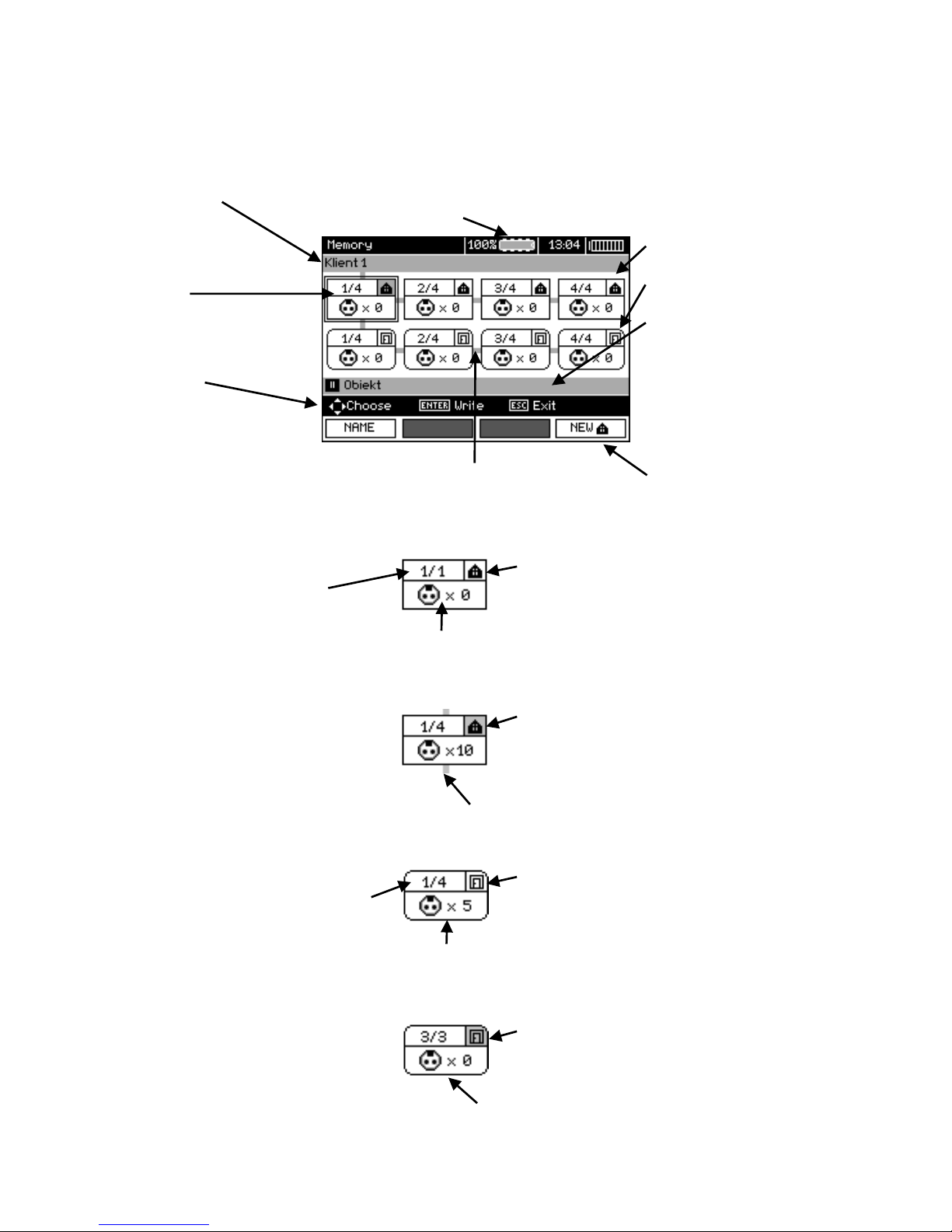
OPERATING MANUAL MPI-530-IT version 1.06
86
4.1.1 The appearance of main windows in the measurement recording
mode
The main folder window
Bar with a client
name / bar for menu
location
Free memory available:
all internal lines visible - 100 %,
no internal line visible - 0 %
Bold borders indicate
location of the cursor
Hint bar
Object icon
Sub-object icon
Bar for the name of
object and sub-object
and (when the cursor
is on the client) client
address (if entered)
Connectors indicating the ability to move
between the icons
Marking of function
buttons
Object without any sub-object
Successive number /
total number of objects
Object symbol
Symbol of the measuring point and the number of such points (for this object)
An object containing at least one sub-object
Object symbol on a grey background
Connector
Sub-object without further sub-objects
Successive number /
total number of sub-objects in
one level
Sub-object symbol
Symbol of the measuring point and the number of such points (for this sub-object)
Sub-object containing more sub-objects
Sub-object symbol on a grey background
Connector (appears when the cursor is over
the icon.)
Page 89
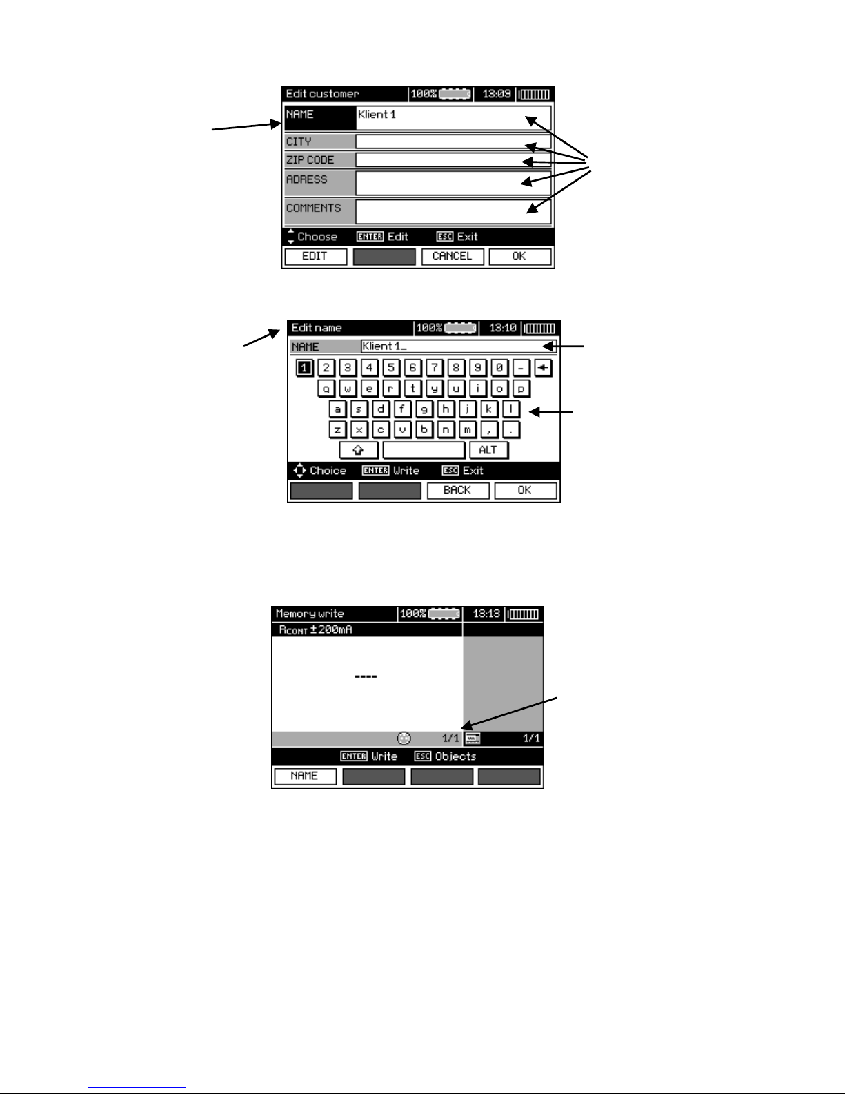
OPERATING MANUAL MPI-530-IT version 1.06
87
Client edit window
Active field
Data fields
Window for entering a name
Information on the
name entering mode
Entry field
On-screen keyboard
To obtain larger fonts set the cursor on Shift and press ENTER.
To obtain special (Polish) fonts set the cursor on ALT and press ENTER.
Window for entering the measurement result
Successive number /
total number of saved
cells
Note:
- Results of measurements performed for all measuring functions can be stored in one memory cell.
- Only the results of the measurements started by pressing START key button can be stored in the
memory (except autozeroing in low-voltage measurement of resistance).
- Complete set of results (main result and supplementary results) for a given measuring function, preset measurement settings, date and time of the measurement are stored in the memory.
- Cells unsaved are not available.
- It is recommended to delete the memory after reading the data or before performing a new series of
measurements that may be stored into the same memory cells as the previous ones.
Page 90
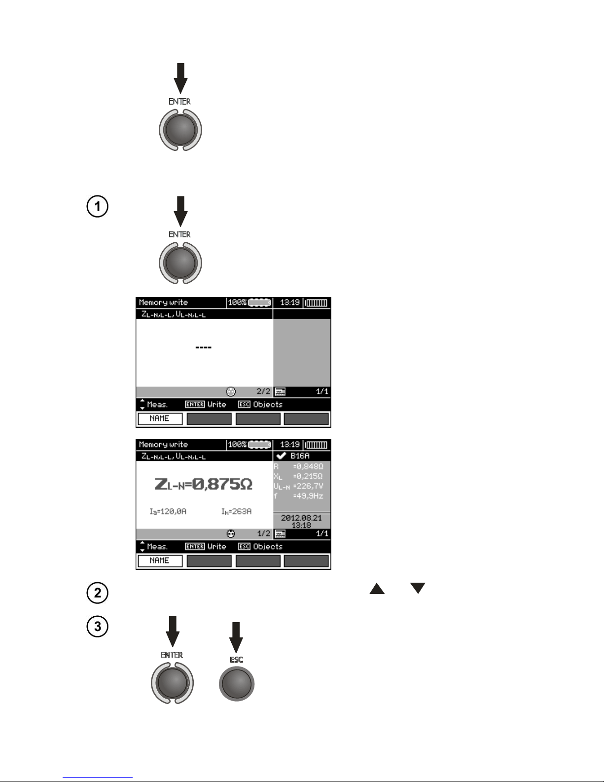
OPERATING MANUAL MPI-530-IT version 1.06
88
4.2 Storing the measurement results data in the memory
Press ENTER after finishing the measurement.
4.2.1 Entering the results without extending the memory structure
Press ENTER again.
Cell free for a given type of
measurement.
A cell reserved for a given
type of measurement.
In order to select a measurement point (cell), use and .
or
Press ENTER, to save the result in the memory or
ESC, to return to displaying the memory structure.
Page 91
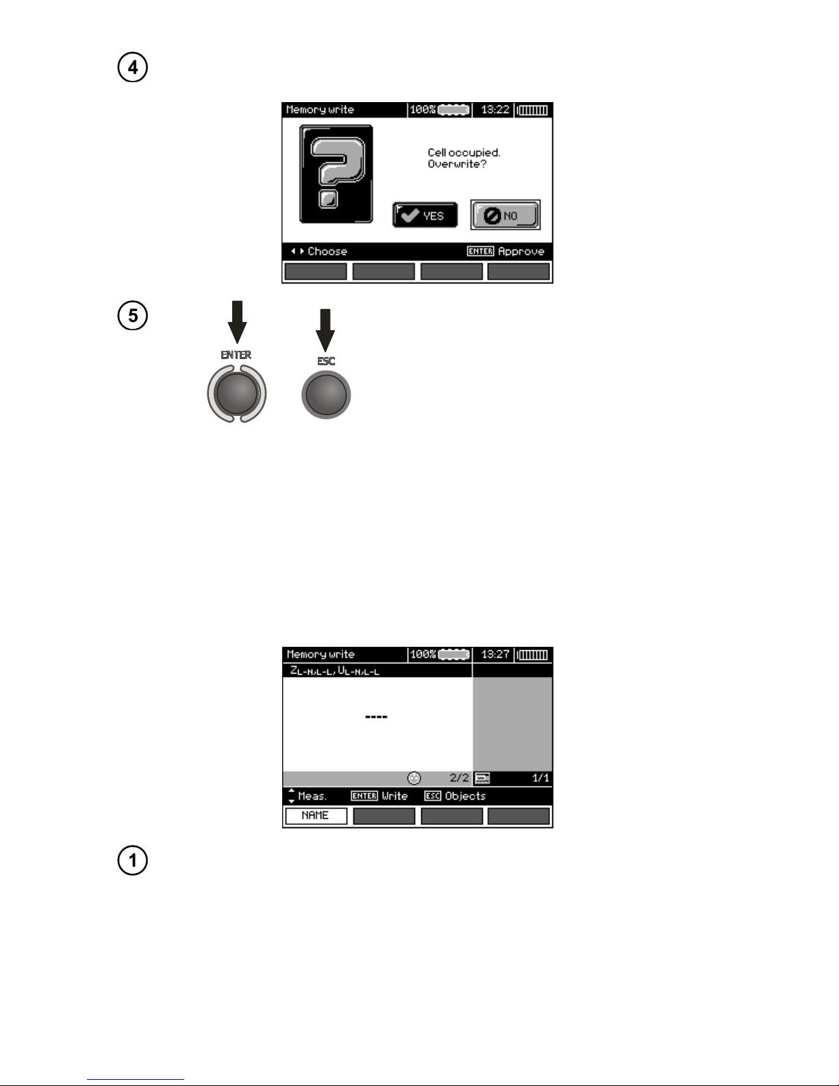
OPERATING MANUAL MPI-530-IT version 1.06
89
If you try to store data in an occupied memory cell, the following warning message will appear:
or
Press ENTER, to overwrite the result or ESC, to
cancel saving.
Note:
- In case of RCD the above warning message will appear also when an attempt is made to store a result of specific measurement (or result component) that has been made at different preset Incurrent
or for a different preset type of RCD (standard / short-time delay / selective) than the measurements
the results of which are already stored in this cell, despite the fact that the memory space designated
for this result component may be free. When results of measurements made for a different type of
RCD or a different In current are stored, the results concerning a given RCD that have been stored
previously will be lost.
4.2.2 Extending the memory structure
Press ESC to start creating the objects.
Page 92
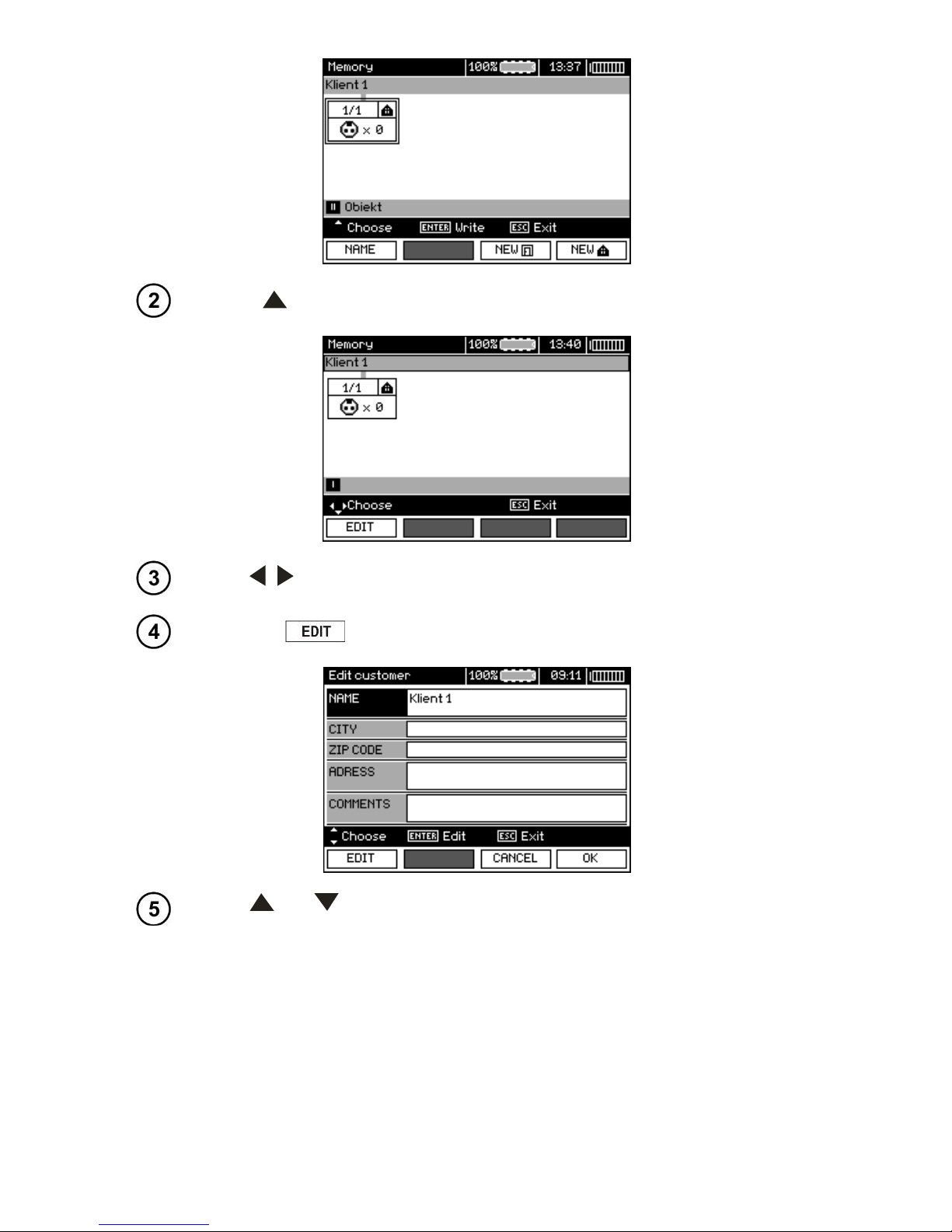
OPERATING MANUAL MPI-530-IT version 1.06
90
Press to set the cursor on Client 1.
Use ,
to move to another client (1 - 10)
.
Press F1 to edit client data.
Use
and
to set the cursor on each item and press ENTER to start the ed-
iting
.
Page 93
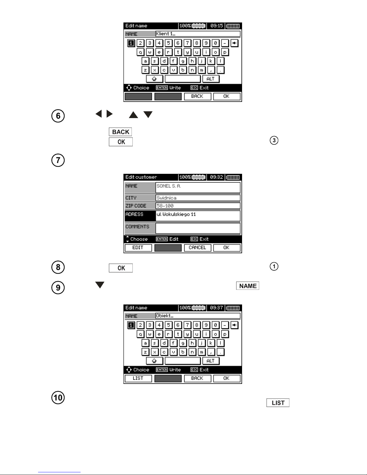
OPERATING MANUAL MPI-530-IT version 1.06
91
Use ,
and
,
to select a character to be typed, and press ENTER to
enter it.
Press F3 to delete typed letters.
Press F4 to confirm data and return to the screen of step .
In this way, you may enter all client data.
Press F4 to confirm data and return to the screen of step .
Use to set the cursor on the object icon. Press F1 to start editing the
object name.
Enter the name of the object in the same way as for the customer data. You may
use the list of proposed names that is available after pressing F1 .
Page 94
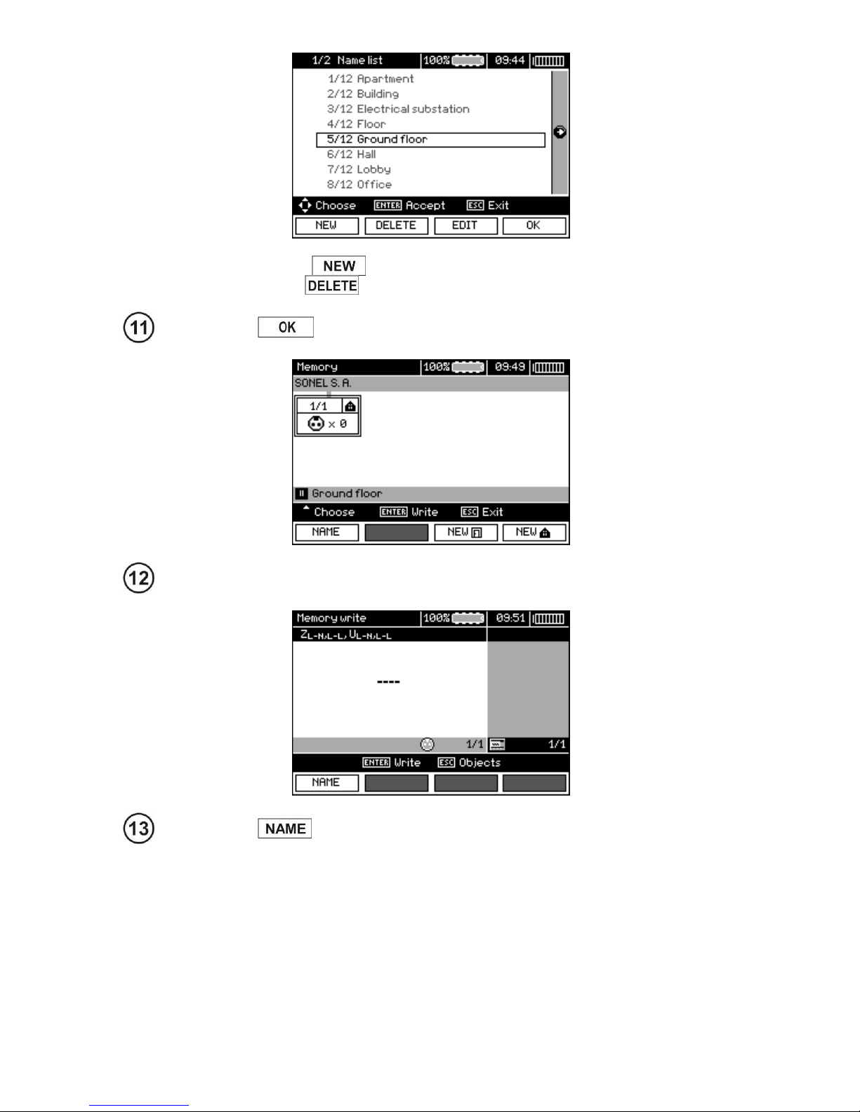
OPERATING MANUAL MPI-530-IT version 1.06
92
After pressing F1 you may add further names to the list (up to 99 items),
and pressing F2 deletes the items.
Press F4 to approve the name that appears on the screen.
Press ENTER, go to the measurement point.
Press F1 to enter the editing of the measuring point name.
Page 95
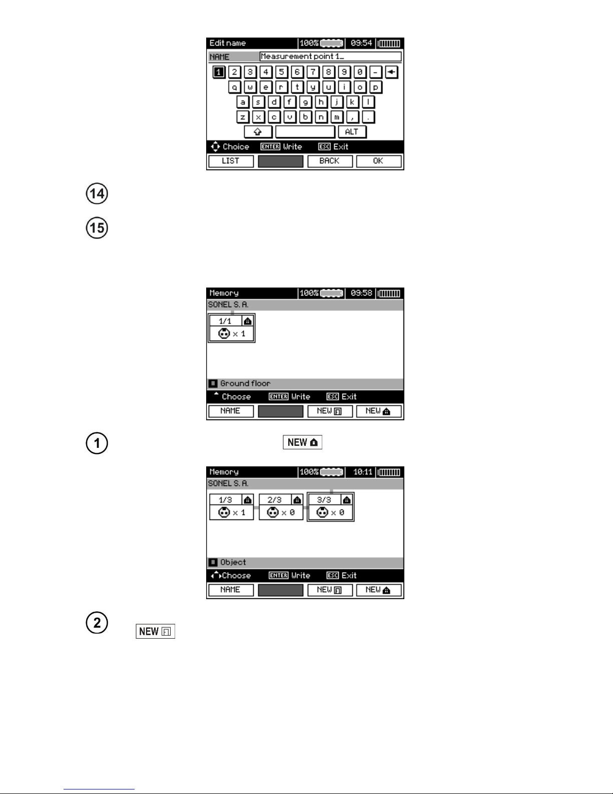
OPERATING MANUAL MPI-530-IT version 1.06
93
Enter the name of the measuring point in the same way as the object name.
Press ENTER, to save the measurement result.
After entering the memory, the user may extend its structure by adding new objects and subobjects as needed.
To add a new object, press F4 .
To add a new sub-object, set the cursor on the chosen object and press F3
.
Page 96
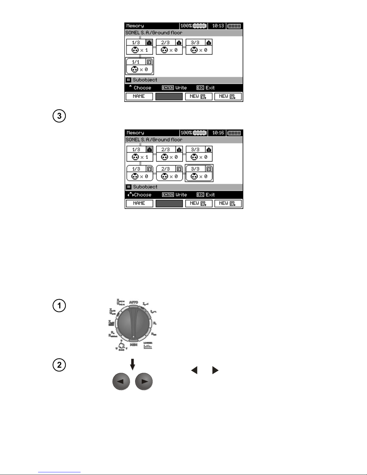
OPERATING MANUAL MPI-530-IT version 1.06
94
Using F3 and F4 you may add new objects and sub-objects (up to 5 levels).
Note:
- New objects (sub-objects in a level) are added on the right side of the object marked with the cursor
(sub-object).
- The screen displays only sub-objects belonging to the object (sub-object) indicated by the cursor.
- Deleting objects and sub-objects is possible only in memory browse mode.
- The name of an object, sub-object or measurement is possible in memory browse mode or after en-
tering entry into the memory after a measurement.
4.3 Browsing and editing the memory
Set the rotary switch of function selection at
MEMposition.
Use and to select "MEMORY BROWSE
AND EDIT”.
Page 97
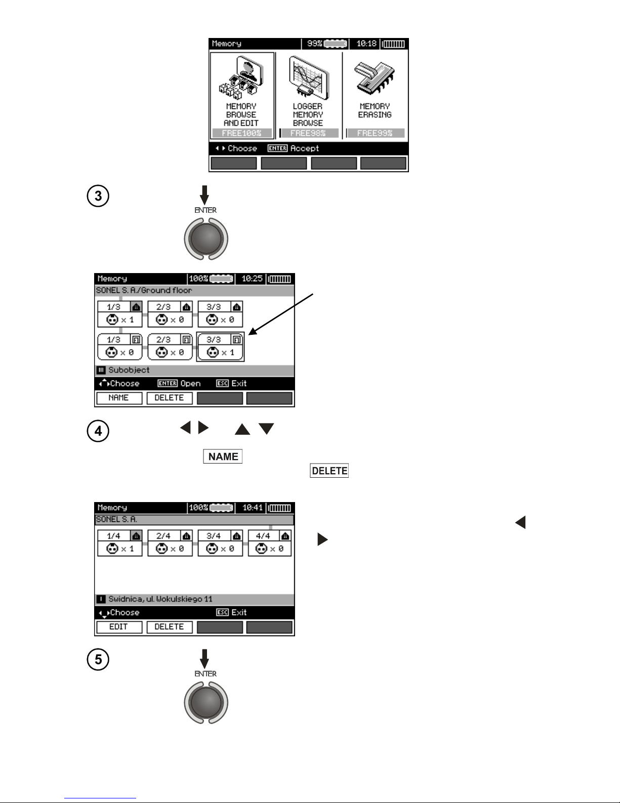
OPERATING MANUAL MPI-530-IT version 1.06
95
Press ENTER push-button.
Last saved measurement in subobject 3,
Level 1
Use , and , to move between objects and sub-objects using the
existing connectors.
Press F1 to enter the option for editing the name of object (subobject) and change it. Press F2 to delete a chosen object (sub-
object) with all its results.
After setting the cursor on the client, use ,
to move to next clients.
After selecting desired object (sub-object) press
ENTER.
Page 98
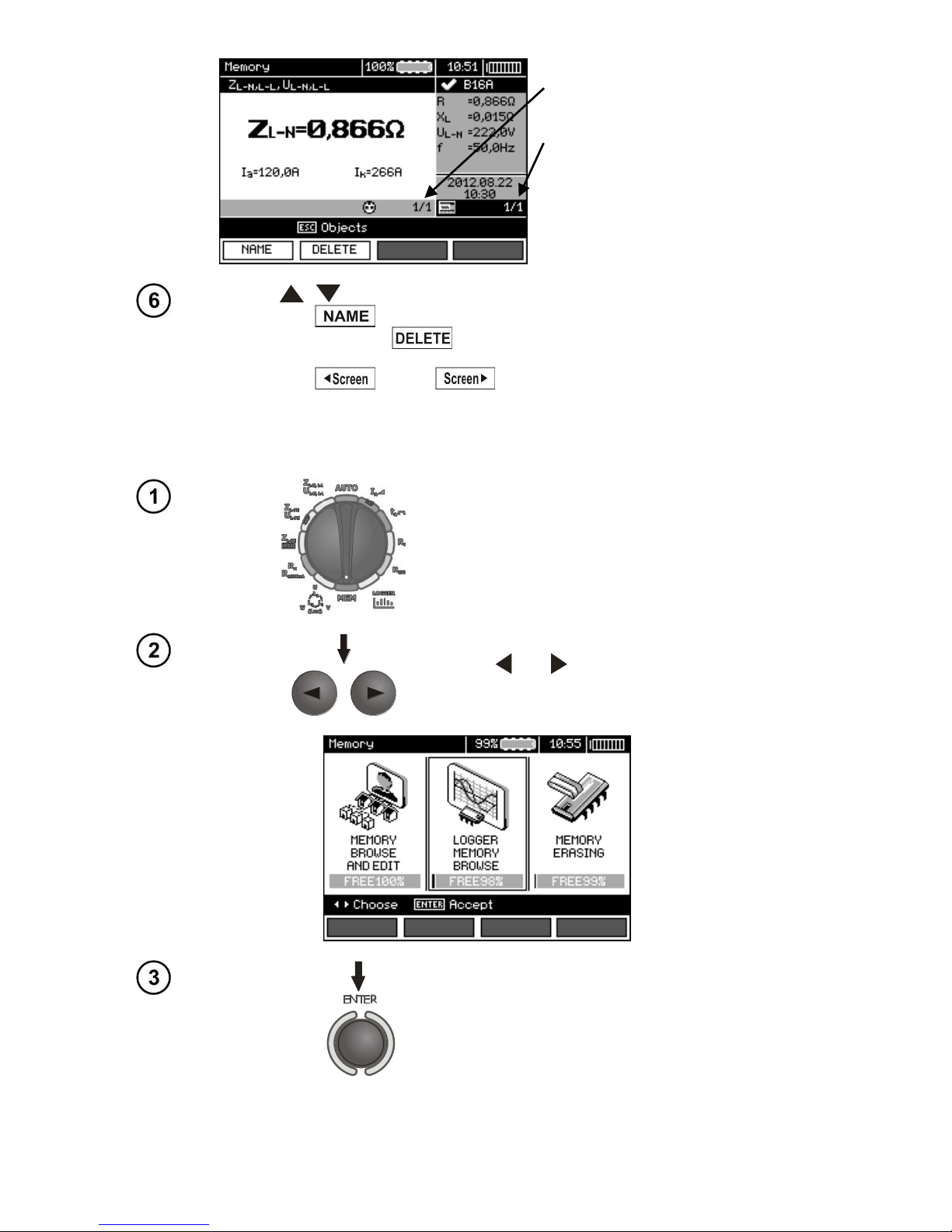
OPERATING MANUAL MPI-530-IT version 1.06
96
The number of measuring point /
number of all measuring points.
The number of measurement type /
number of all measurements types
at that point.
Use , to change the measuring point.
Press F1 to enter the editing of the measuring point name and to
change it. Press F2 to delete a chosen measuring point with all its
results.
Press F3 and F4 to display all individual types of results for
a given point.
4.4 Browsing the recorder memory.
Set the rotary switch of function selection at
MEMposition.
Use and to select "LOGGER MEMORY
BROWSE".
Press ENTER push-button.
Page 99
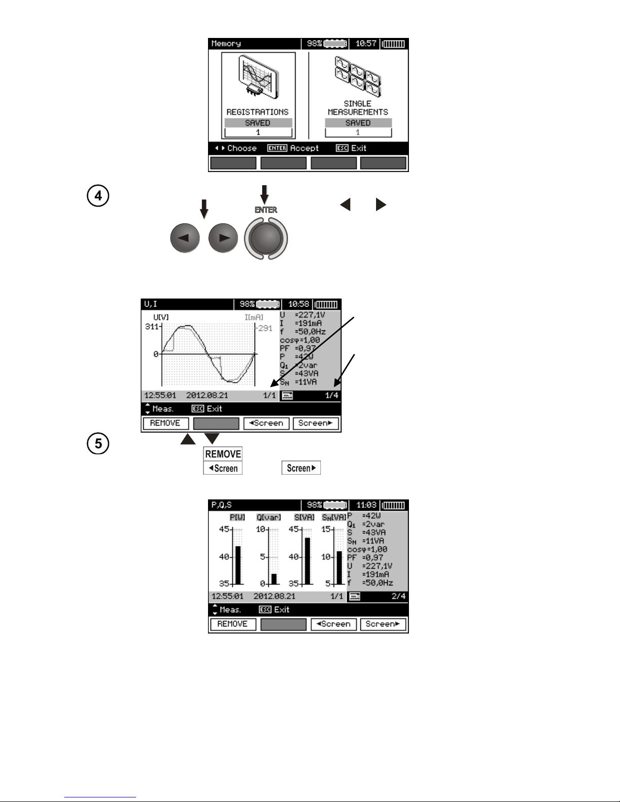
OPERATING MANUAL MPI-530-IT version 1.06
97
Use and to choose between browsing
recorded results or single measurements.
Press ENTER push-button.
Single measurements
The number of a measurement /
number of all measurements.
Number of the screen with results /
number of all screens with results.
Use , to display the results of subsequent measurements.
Press F1 to delete a chosen measurement with all its results.
Press F3 and F4 to display all individual results for a given
measurement.
Page 100
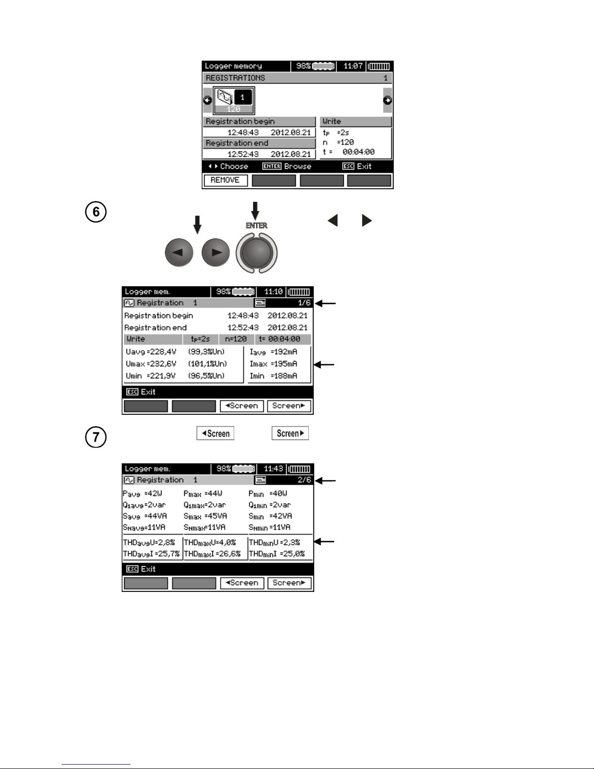
OPERATING MANUAL MPI-530-IT version 1.06
98
Records
Use and to select a record to browse.
Press ENTER push-button.
Number of the screen with
results / number of all
screens with results.
Statistical values of voltage
and current.
Press F3 and F4 to display individual results for a given record.
Number of the screen with
results / number of all
screens with results.
Statistical values of power
and THD.
 Loading...