

Page 1
Page 2
Page 3
OPERATING MANUAL
INSULATION RESISTANCE METER
MIC-5001
SONEL S.A.
ul. Wokulskiego 11
58-100 Świdnica, Poland
Version 1.01 10.10.2016
Page 4

MIC-5001 OPERATING MANUAL
version 1.01
2
MIC-5001 is a modern, high-quality measuring device, which is easy and safe to use. Please acquaint yourself with this manual in order to avoid measuring errors and prevent possible problems in
operation of the meter.
Page 5

MIC-5001 OPERATING MANUAL
version 1.01
3
CONTENTS
1 SAFETY .................................................................................................................... 5
2 TURNING THE METER ON AND ACTIVATING SCREEN BACKLIGHT. . 6
3 METER CONFIGURATION .................................................................................. 6
4 MEASUREMENTS .................................................................................................. 9
4.1 MEASUREMENT OF INSULATION RESISTANCE ........................................................... 9
4.1.1 Double-lead measurement ............................................................................. 9
4.1.2 Three-lead measurement ............................................................................. 14
4.2 MEASURING THE RESISTANCE WITH INCREASING VOLTAGE – RAMPTEST ................. 15
4.3 VOLTAGE MEASUREMENT ..................................................................................... 19
5 MEMORY OF MEASUREMENT RESULTS .................................................... 20
5.1 STORING THE MEASUREMENT RESULTS IN THE MEMORY ................................ ......... 20
5.2 VIEWING MEMORY DATA ....................................................................................... 22
5.3 DELETING MEMORY DATA ..................................................................................... 23
5.3.1 Deleting bank data ................................................................ ....................... 23
5.3.2 Deleting the whole memory ......................................................................... 24
6 DATA TRANSMISSION ....................................................................................... 25
6.1 COMPUTER CONNECTION ACCESSORIES ................................................................ 25
6.2 DATA TRANSMISSION WITH USB JOINT .................................................................. 25
7 PROCESSING THE MEASUREMENT RESULTS ........................................... 26
8 SOFTWARE UPDATES................................ ................................ ........................ 27
9 POWER SUPPLY .................................................................................................. 27
9.1 MONITORING THE POWER SUPPLY VOLTAGE .......................................................... 27
9.2 CHARGING THE RECHARGEABLE BATTERIES ........................................................... 28
9.3 GENERAL PRINCIPLES REGARDING USING NI-MH RECHARGEABLE BATTERIES ........ 29
10 CLEANING AND MAINTENANCE ................................................................... 30
11 STORAGE .............................................................................................................. 30
12 DISMANTLING AND DISPOSAL ...................................................................... 30
13 TECHNICAL SPECIFICATIONS ....................................................................... 31
13.1 BASIC DATA .......................................................................................................... 31
13.2 ADDITIONAL UNCERTAINTIES ACCORDING TO IEC 61557-2 (R
ISO
) ......................... 33
14 ACCESSORIES ...................................................................................................... 33
14.1 STANDARD EQUIPMENT ........................................................................................ 33
14.2 OPTIONAL ACCESSORIES ....................................................................................... 34
Page 6

MIC-5001 OPERATING MANUAL
version 1.01
4
15 MANUFACTURER ............................................................................................... 35
16 LABORATORY SERVICES ................................................................................ 36
Page 7

MIC-5001 OPERATING MANUAL
version 1.01
5
1 Safety
MIC-5001 meter is designed for performing check tests of protection against electric shock in
mains systems. The meter is used for making measurements and providing results to determine safety
of electrical installations. Therefore, in order to provide conditions for correct operation and accuracy
of obtained results, the following recommendations must be observed:
Before you proceed to operate the meter, acquaint yourself thoroughly with the present manual
and observe the safety regulations and specifications provided by the producer.
Any application that differs from those specified in the present manual may result in a damage to
the device and constitute a source of danger for the user.
MIC-5001 meters must be operated only by appropriately qualified personnel with relevant certifi-
cates authorising the personnel to perform works on electric systems. Unauthorized use of the me-
ter may result in its damage and may be a source of serious hazard to the user.
During measurements of insulation resistance, dangerous voltage of approx. 5kV occurs at the
ends of measurement wires of the meter.
Before the measurement of insulation resistance you must be sure that tested object is discon-
nected from the power supply.
During the measurement of insulation resistance do not disconnect test leads from the tested ob-
ject before the measurement is completed (see par. 4.1); otherwise the capacitance of the object
will not be discharged, creating the risk of electric shock.
Using this manual does not exclude the need to comply with occupational health and safety regu-
lations and with other relevant fire regulations required during the performance of a particular type
of work. Before starting the work with the device in special environments, e.g. potentially fire-
risk/explosive environment, it is necessary to consult it with the person responsible for health and
safety.
It is unacceptable to operate the device when:
a damaged meter which is completely or partially out of order,
a meter with damaged insulation,
a meter stored for an excessive period of time in disadvantageous conditions (e.g. excessive
humidity).If the meter has been transferred from a cool to a warm environment with a high level
of relative humidity, do not start measurements until the meter is warmed up to the ambient
temperature (approximately 30 minutes).
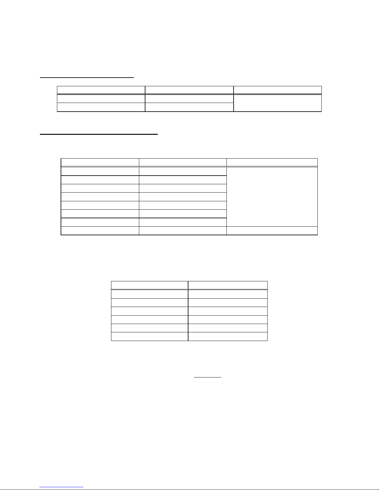
Remember that bAt message appearing on the display indicates insufficient voltage of power
supply and the need to recharge the batteries.
Message ErrX displayed in the main field , where X is a number from 0 to 9, indicate incorrect op-
eration of the meter. If after restarting the device this situation is repeated - it indicates that the
meter is damaged. Please contact the manufacturer's service.
Before measurement, choose a correct measurement function and make sure that test leads are
connected to respective measuring terminals.
Do not power the meter from sources other than those listed in this manual.
The R
ISO
inputs of the meter are protected electronically from overload (e.g. due to having been
connected to a live circuit) up to 750V rms for 60 seconds.
Repairs may be performed only by an authorised service point.
Note:
Due to continuous development of the meter’s software, the actual appearance of the display,
in case of some of the functions, may slightly differ from the display presented in this operating manual.
Page 8
MIC-5001 OPERATING MANUAL
version 1.01
6
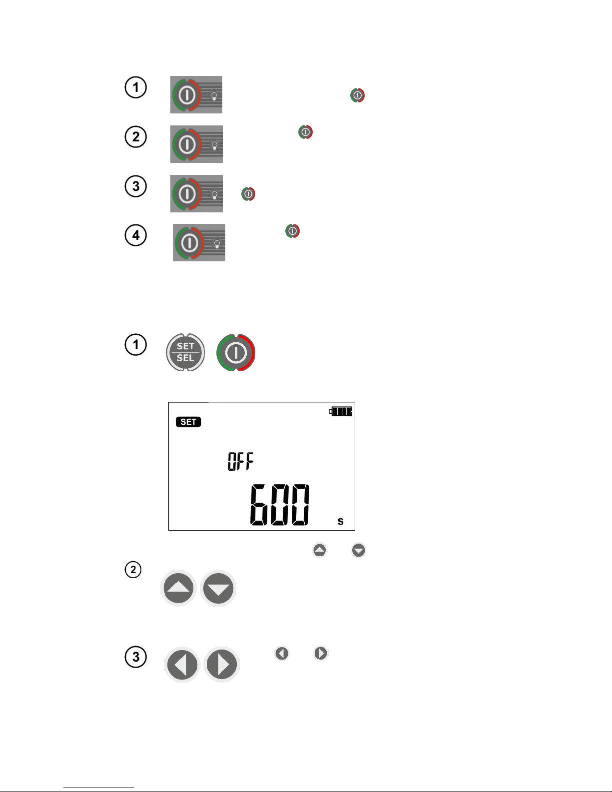
2 Turning the meter ON and activating screen backlight.
Turn on the meter with button.
Short press button to turn the screen backlight
on; press the button again to turn the backlight off.
Turn on the meter by pressing and keeping button
pressed. for approx. 2 sec.
Failure
Pressing button for approx. 7 seconds will turn
off the meter in case of emergency.
3 Meter Configuration
+
Turn on the meter by pressing and keeping
SET/SEL button pressed.
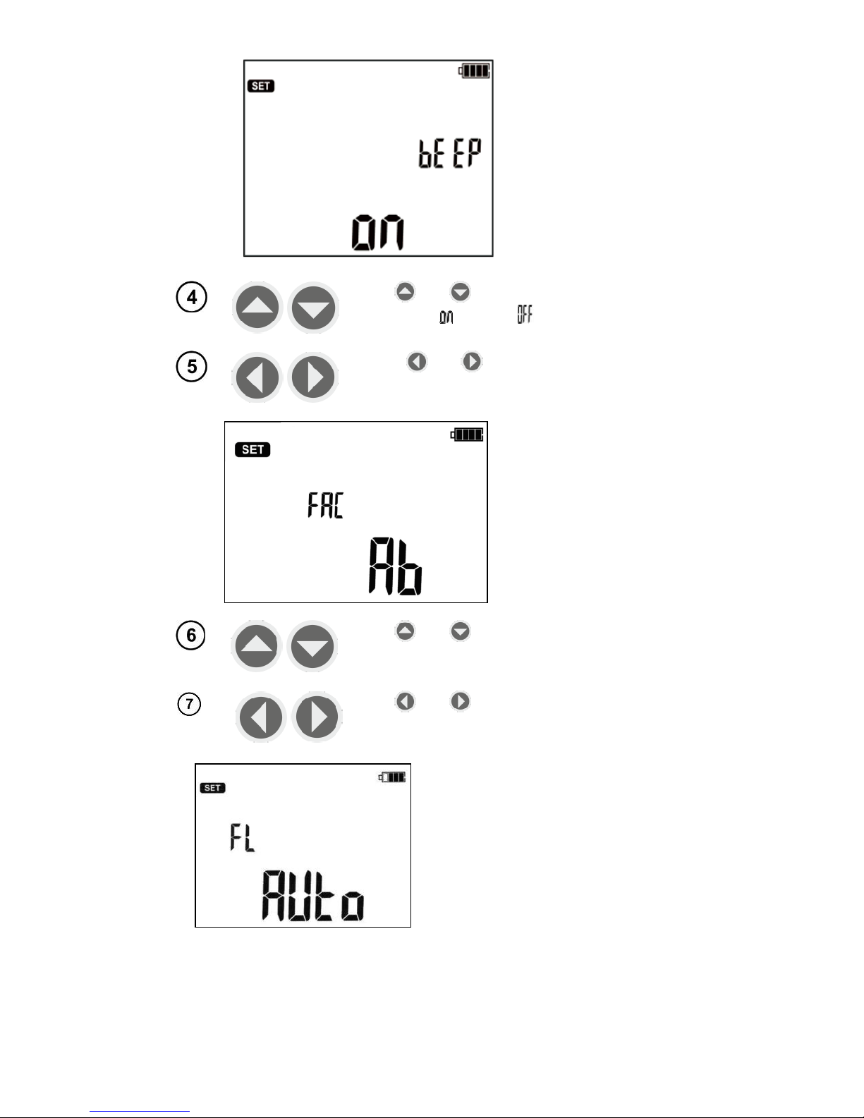
Use buttons and to set Auto-OFF time or
to inactivate this function (horizontal lines – AutoOFF function is inactive). Auto-OFF function is
used to turn-off inactive meter after a preselected
time (300, 600 or 900 sec.). When the user
switches the meter off, it will generate a beep after the set time.
Use and buttons to enter the screen with
audio message settings: bEEP.
Page 9
MIC-5001 OPERATING MANUAL
version 1.01
7
Use and buttons to turn the audio messages ON ( ) or OFF ( ).
Press and buttons to enter the settings
of absorption coefficients FAC.
Use and buttons to set DAR parameters
for Ab1, Ab2 or polarization index PI.
Use and buttons to move to the filtration
FL settings.
MIC-5001 has an analogue filter which
damps variable component of current
and allows measurements in an environment with strong electromagnetic interference.
Activation of FL filtration causes a slight
increase of time needed to stabilize the
measurements. The meter has 3 setting
modes of filter operation.
Page 10
MIC-5001 OPERATING MANUAL
version 1.01
8
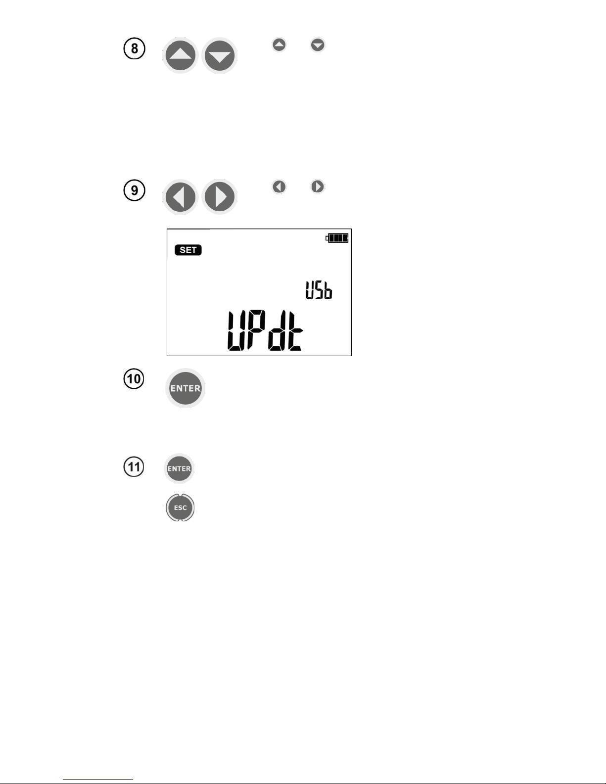
Use and
buttons to set the filtration mode:
"AUTO" – Detection of noise activates the
filter. "NOISE" mnemonic is displayed. The
recommended setting.
"ON" – filter always ON, the detection of
noise (despite enabled filter) results in displaying "NOISE" mnemonic.
"OFF" – filter always OFF, the detection of
noise results in displaying "NOISE" mnemonic.
Use and buttons to enter the screen with
software update UPdt.
Press ENTER to enter the update mode. The update
process is described in Chapter 8
After changing the parameters, you may exit SETUP menu (not appli-
cable for Update screen):
Press ENTER to memorize settings
or use ESC button to go to the measurement screen
without approving the changes.
Page 11
MIC-5001 OPERATING MANUAL
version 1.01
9
4 Measurements
4.1 Measurement of insulation resistance
WARNING:
The tested object must not be live.
Attention:
During measurement, especially of high resistances, make sure that test leads
do not touch each other and probes (crocodile clips), because such a contact
may cause the flow of surface currents resulting in additional error in measurement results.
WARNING:
In a dusty and humid environment, do not open plugs of USB sockets and
charger.
4.1.1 Double-lead measurement
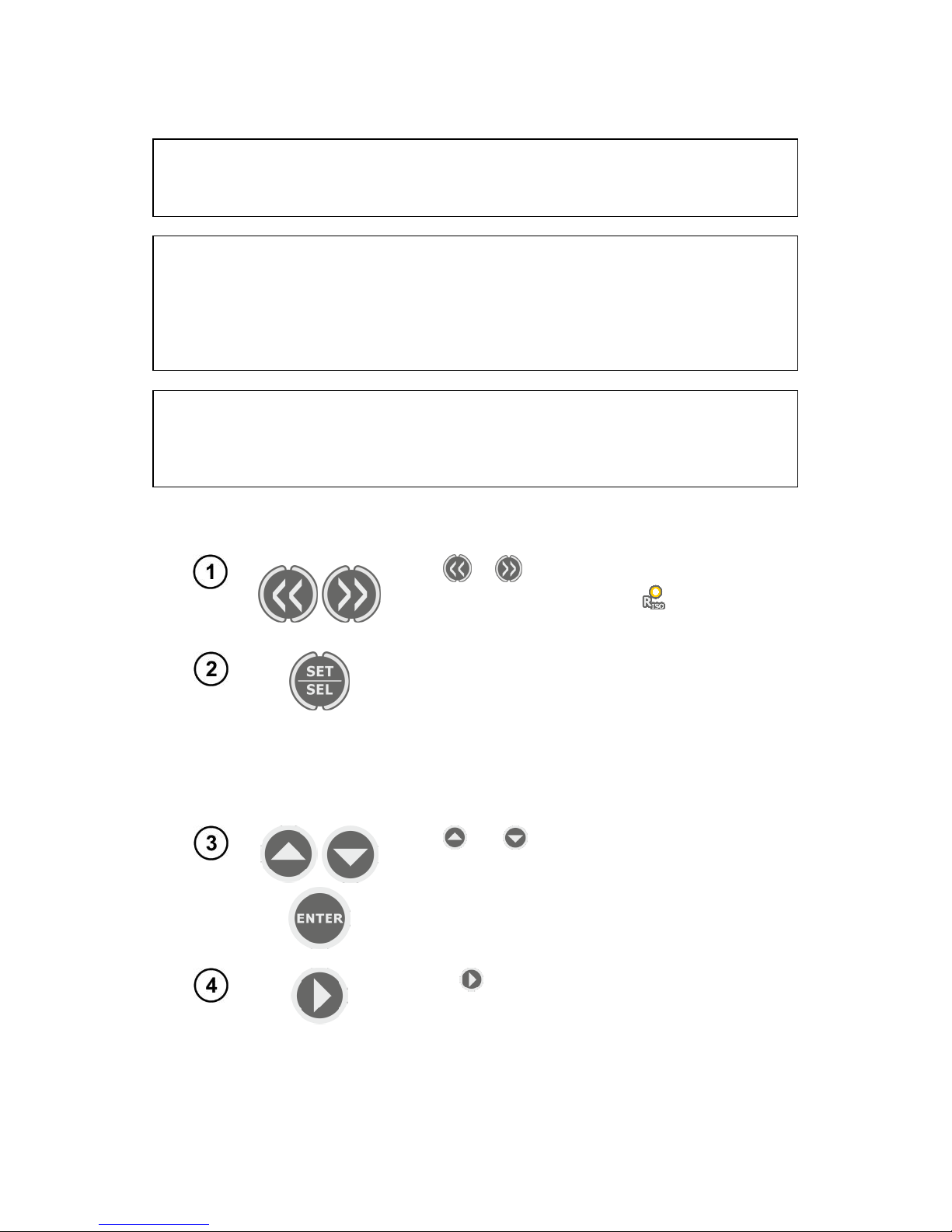
Use or button to enter the measurement of R
ISO
(yellow LED is ON ). The me-
ter is in the voltage measurement mode.
Press SET/SEL button to enter the selection of:
measuring voltage U
ISO
(50 V…500 V at
50 V steps and above 500 V at 100 V
steps)
times for calculating absorption coeffi-
cients t1, t2, t3 (up to 600 s)
interval between points of characteristics
ChA (15, 30, 45 or 60 sec.).
Use and buttons to set U
ISO
value
confirm by pressing ENTER
or use button to enter the setting
of times
for calculating the absorption coefficients
.
Page 12
MIC-5001 OPERATING MANUAL
version 1.01
10
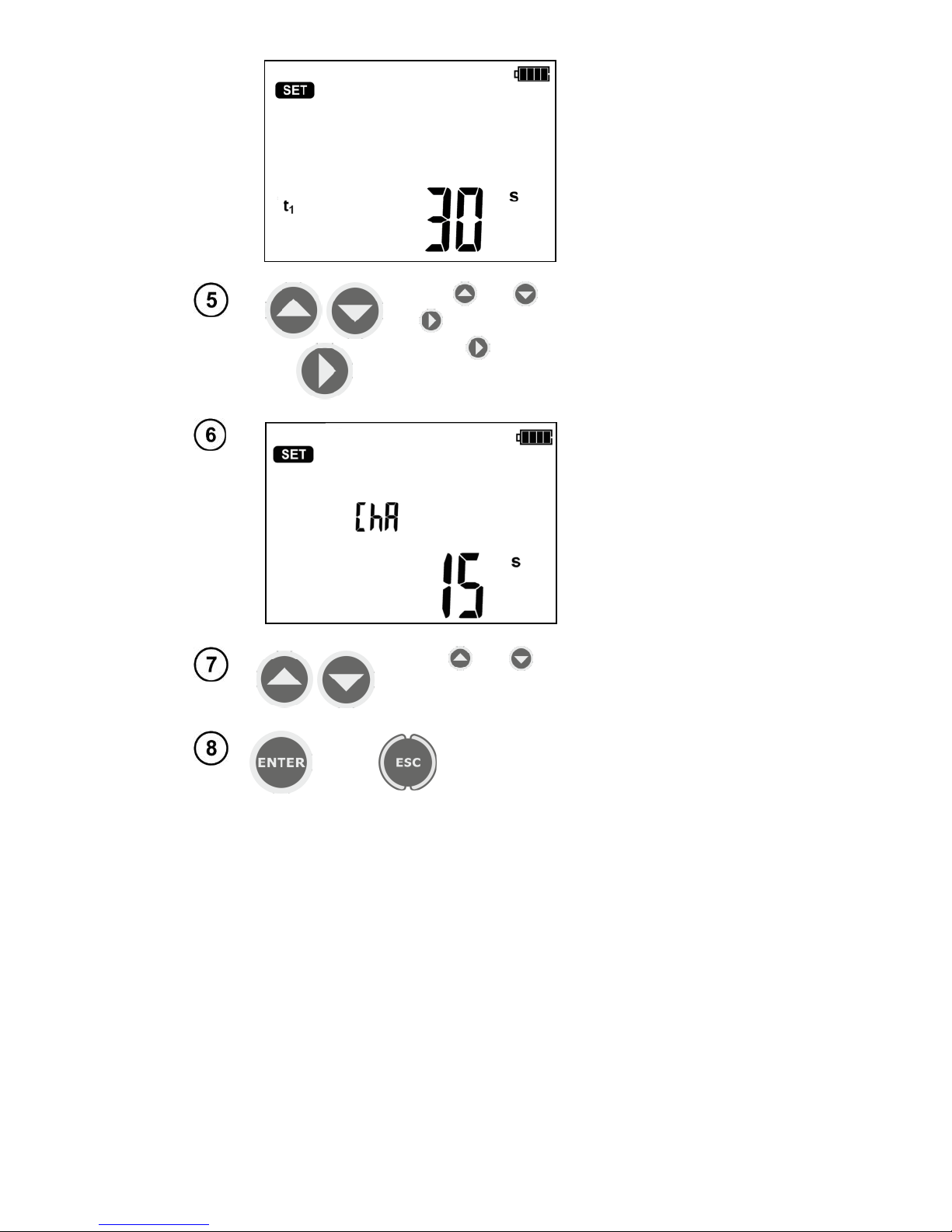
Use and buttons to set t1 value, use
button to start setting t2 and then t3 value.
Press again to enter the setting of time interval ChA of recording R
ISO
.
Use and buttons to set the interval value. Horizontal lines indicate unavailability of recording characteristics.
or
Press
ENTER
to confirm settings or
press ESC to exit without saving the
changes.
Page 13
MIC-5001 OPERATING MANUAL
version 1.01
11
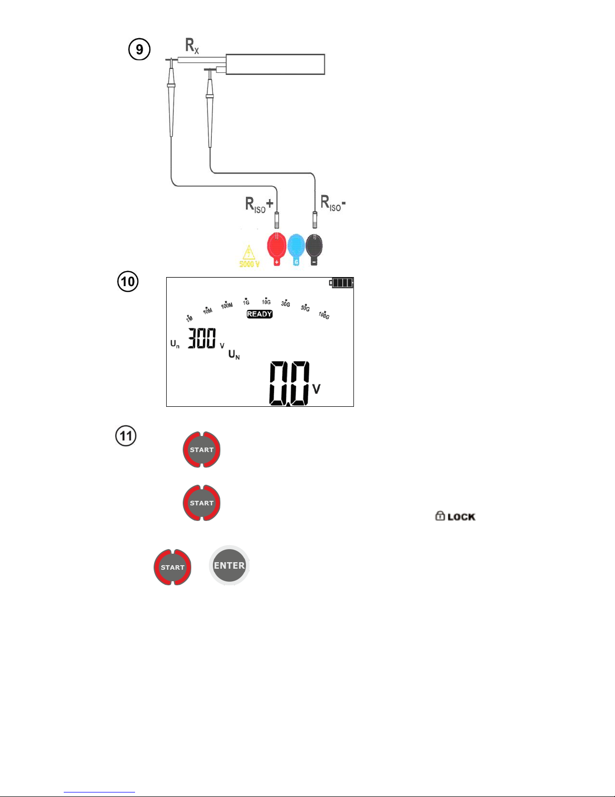
The meter is ready
for measurement.
Press and hold START push-button.
The measurement is performed continuously until you release the button or the pre-set time is
reached.
for 5 seconds.
or
+
In order to maintain (hold) the measurement
press and hold START button 5 sec. for 5 sec.
or press ENTER while holding START . The but-
tons may be released after symbol is
displayed, which indicates the automeasurement. The measurement will end after
the longest pre-set time (t1, t2 or t3) runs out. To
interrupt or terminate the measurement earlier in
the absence of pre-set t1, t2 or t3 values (measurement without time limit), press again START
or ESC button.
Connect test
leads according to
the drawing.
Page 14
MIC-5001 OPERATING MANUAL
version 1.01
12
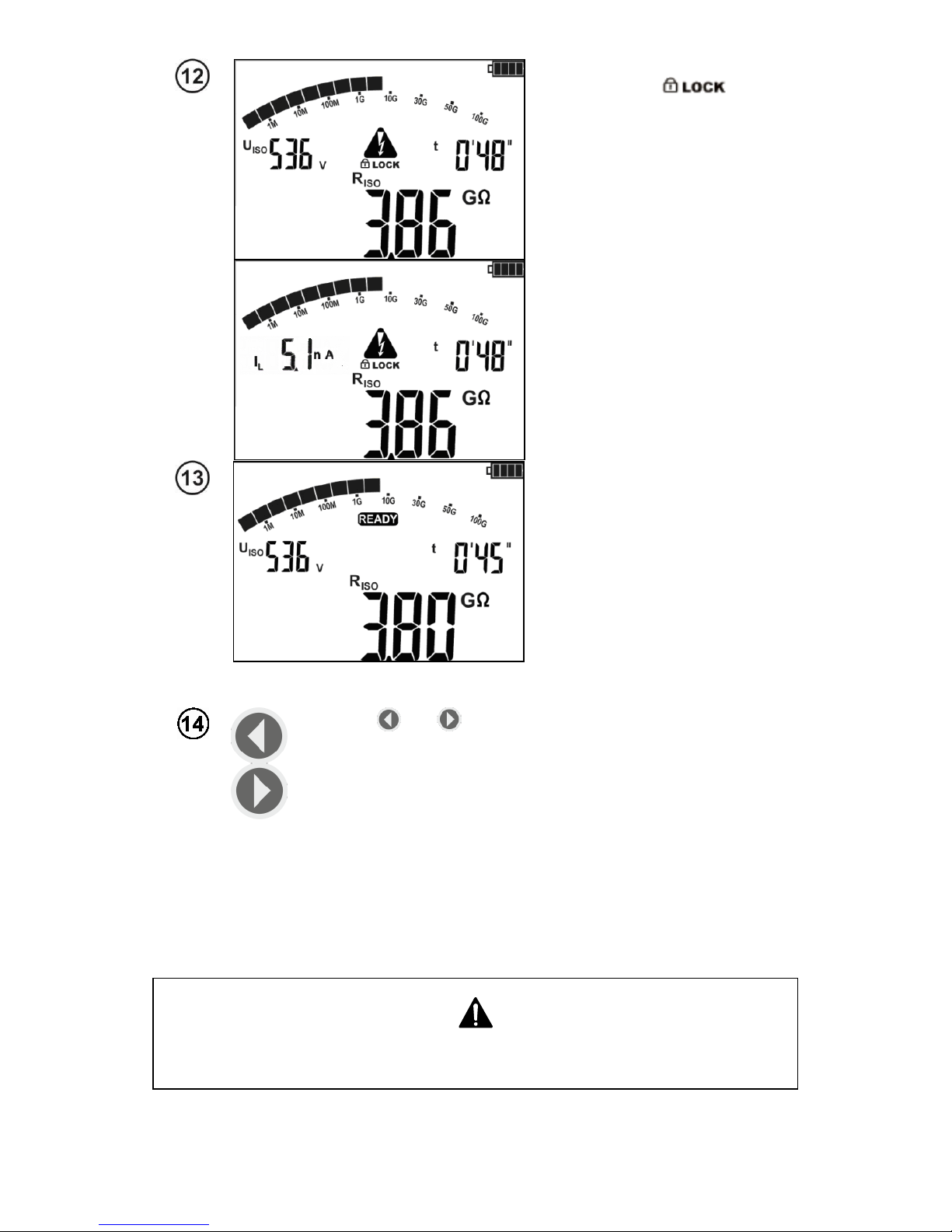
View of the screen during
measurement.
means that the measurement
was started with ENTER button or by pressing and holding START button for approx.
5 sec.
Use SET/SEL to display values of leakage current IL.
After the measurement is
completed or stopped, read
the result. The results of all
completed measurements will
be displayed (even when the
measurement was interrupted/stopped e.g. after 60 seconds). When the meter
switched into standby mode,
the measurement result may
be recalled by pressing
ENTER.
Use and to see individual components of the result
in the following order:
R
ISO→IL
→Ab2→Ab1→Rt3→It3→Rt2→It2→Rt1→It1
→R
ISO
.
If the measurement is stopped, the displayed values will
present the results of partial measurements that have
been completed and "---" will represent uncompleted partial measurements.
If the characteristic was measured, then the measurement
results may be read between It1 and R
ISO
.
Note:
During measurements of insulation resistance, dangerous voltage of approx.
5kV occurs at the ends of measurement wires of the meter.
Page 15
MIC-5001 OPERATING MANUAL
version 1.01
13
It is forbidden to disconnect test leads before the measurement is completed.
Disconnection may lead to high voltage electric shock and prevents discharging of the tested object.
- Disabling t2 will also disable t3.
- Timer measuring the measurement time is started when U
ISO
voltage is stabilized.
- Symbol LIMIT means operation with limited inverter power. If this condition persists for 20 seconds,
the measurement is interrupted.
- If the timer reaches characteristic points ('tx' times or characteristic times), then for 1s instead U
ISO
a
symbol (mnemonic) of this point is displayed which is accompanied by a long beep.
- If the value of any of the measured partial resistance is out of range, the value of the absorption coef-
ficient is not shown - horizontal dashes are displayed.
- During the measurement LED is flashing in yellow.
- When the measurement is complete, capacity of the tested object is discharged by shorting terminals
R
ISO
+ and R
ISO
- with resistance of approx. 100 k. Message "diS" is displayed. Do not disconnect the
test leads before the object capacity id discharged.
- When during viewing the results, voltage is present at terminals R
ISO
, LED R
ISO
will blink in red and
additional two-tone beep will be generated.
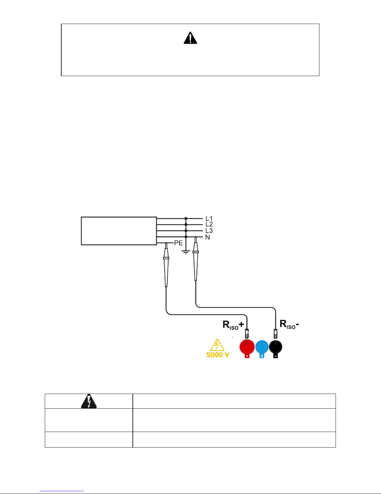
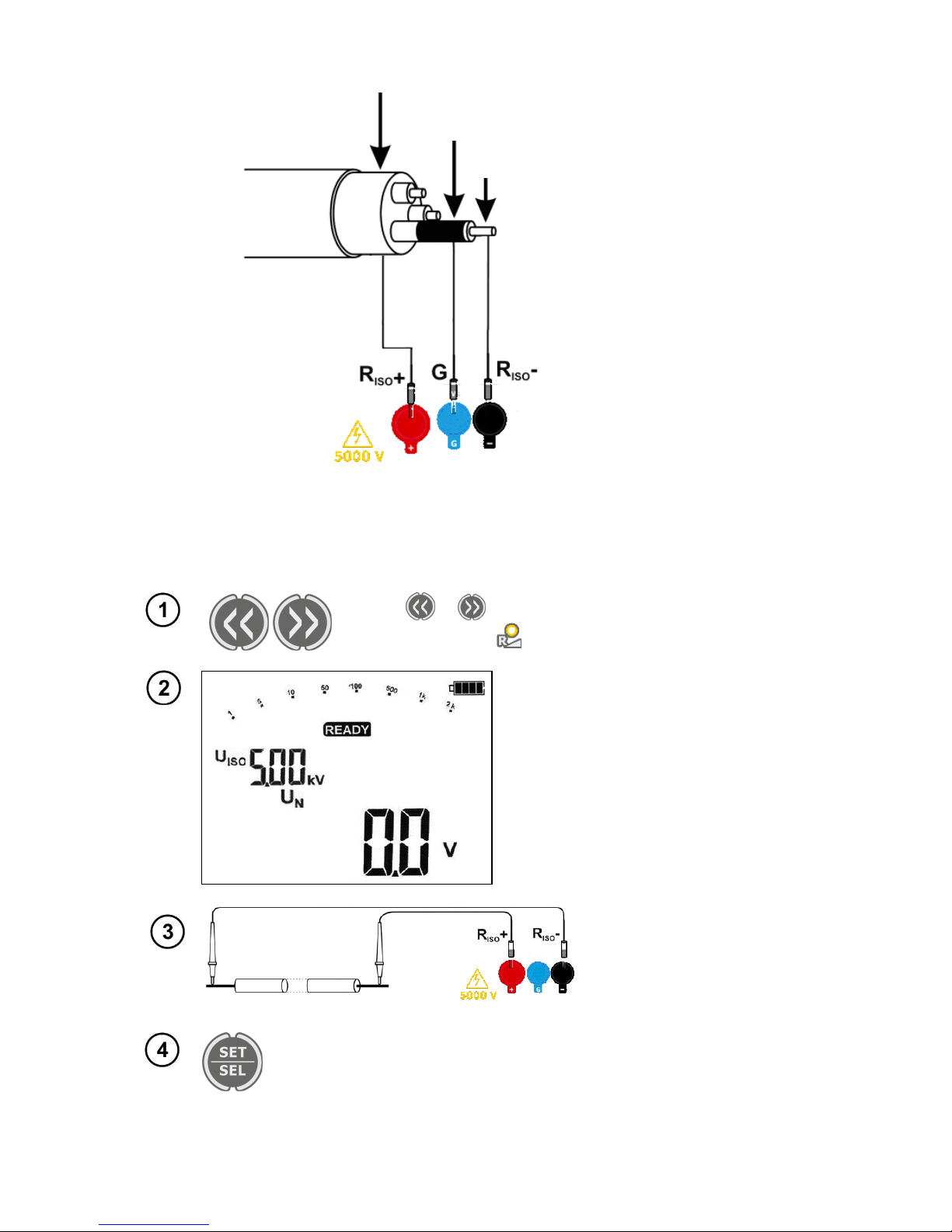
- In case of power cables measure the insulation resistance between each conductor and other con-
ductors shorted and grounded (figure below).
Additional information displayed by the meter
Test voltage is present on terminals of the meter.
NOISE!
Interference voltage higher than 25V but lower than 50V, is present on the tested object. Measurement is possible but may be
burdened with additional uncertainty.
READY disappears, LED
lights red, two-tone beep
Interference voltage higher than 50 V, is present on the tested object. The measurement is blocked.
Page 16
MIC-5001 OPERATING MANUAL
version 1.01
14
LIMIT I!
Activation of current limit. The symbol displayed is accompanied
by a continuous beep.
Breakdown of the tested object insulation, the measurement is interrupted. The message appears after displaying LIMIT I! for 20 s
during the measurement, when the voltage previously reached the
nominal value.
, RISO LED is
blinking in red and two-
tone acoustic signal is
generated
During the measurement, AC voltage appeared or the object cannot be discharged for 30 seconds. Immediately disconnect the
test leads.
4.1.2 Three-lead measurement
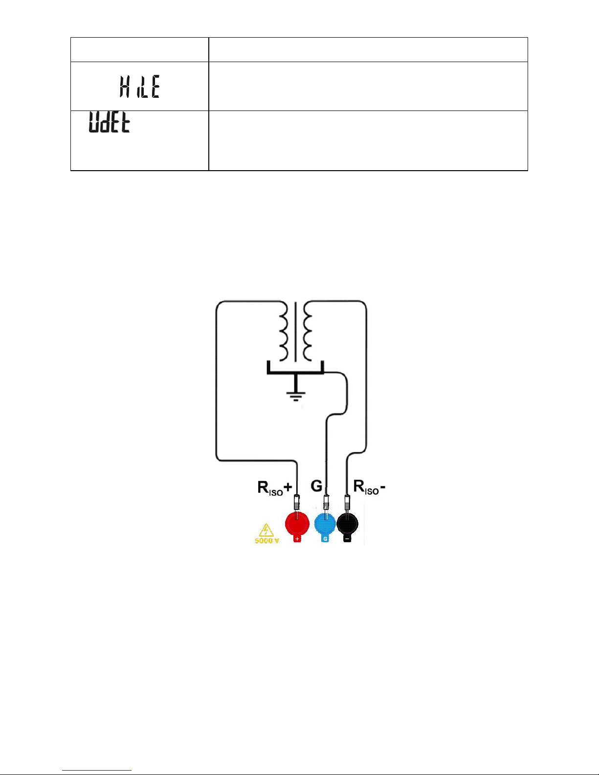
In order to eliminate the influence of surface resistance in transformers, cables, etc. the
three-lead measurement is used. For example:
at the measurement of inter-winding resistance of a transformer, G socket of the meter should
be connected to the transformer tank;
when measuring insulation resistance between one of the cable conductors and the cable jack-
et, the effect of surface resistances (important in difficult weather conditions) is eliminated by
connecting a piece of metal foil insulating the tested conductor with G socket of the meter;
Page 17
MIC-5001 OPERATING MANUAL
version 1.01
15
The same shall apply when measuring the resistance between two conductors of the cable, at-
taching to G terminal other conductors that do not take part in the measurement.
4.2 Measuring the resistance with increasing voltage – RampTest
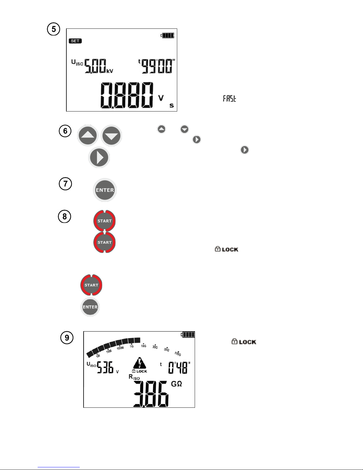
Use or button to enter RampTest measurement of
(yellow LED is ON ).
The meter indicates readiness for
measurement with increasing voltage.
Connect test leads to
the tested object.
Use SET/SEL button to enter the settings of the measuring voltage U
ISO
and measurement duration settings.
Setting of the measuring voltage U
ISO
is adjusted within the range
from 50 V to 500 V in 50 V steps, whereas above 500 V to 5 kV in
100 V steps.
Conductor
Cable sheath
Metal foil wrapped around the conductor insulation
Page 18
MIC-5001 OPERATING MANUAL
version 1.01
16
The measurement time may be set in
the range from 5 sec. to 99 min. Setting
U
ISO
values and the measurement time
allows to calculate the voltage increase
ratio, expressed in V/s. The voltage increase ratio adjusted from 0.005 V/s
(for U
ISO
= 50 V and t = 99 min.) up to
996 V/s. (for U
ISO
= 5.0 kV and t = 5 s.)
When the setting of the voltage increase
ratio is ≥ 50 V/s, then the meter will dis-
play message not showing the value of the measured resistance and but
only the value of breakdown voltage.
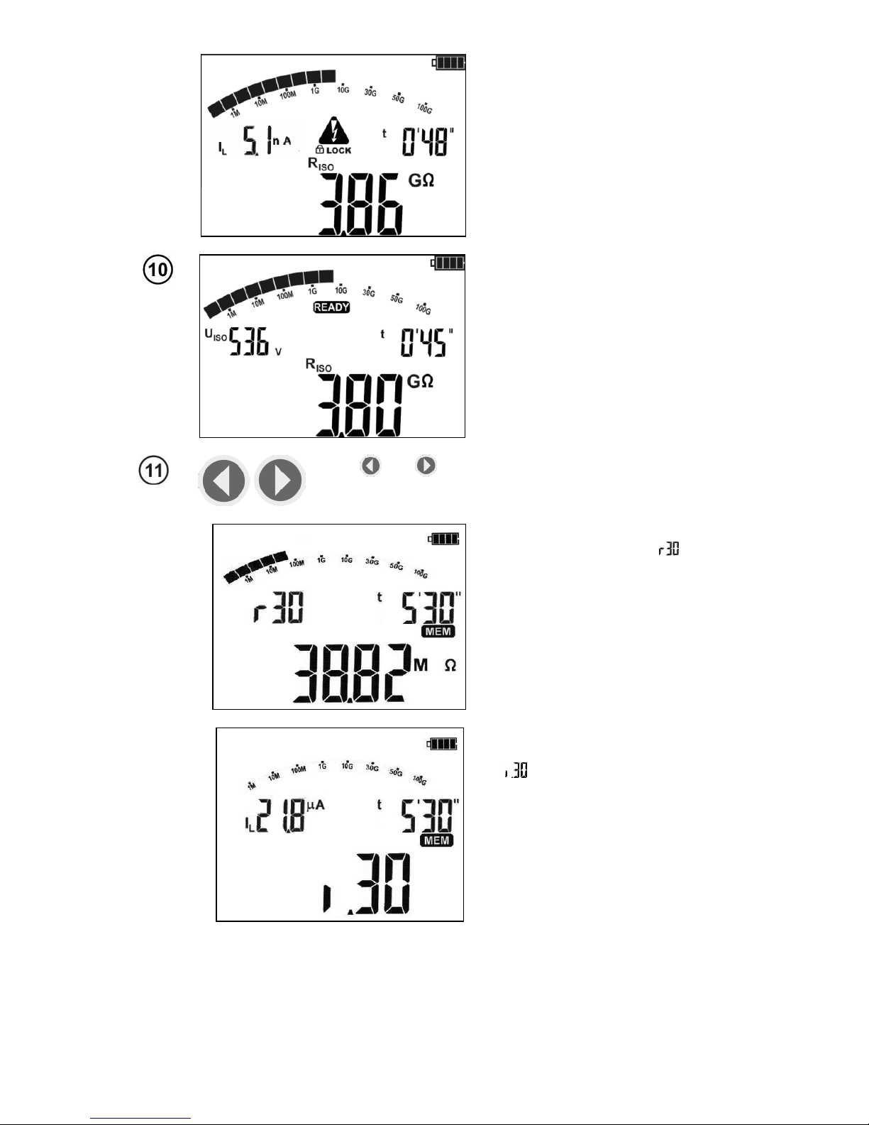
Use and buttons to set voltage U
ISO
, signalled by
pulsating light. Use button to set time t=XX’ for values
expressed in minutes or press again button to set time
t=XX” expressed in seconds.
Press ENTER to confirm the settings.
To start the measurement press and hold START button.
The measurement is performed continuously until you release the button or the pre-set time is reached.
for 5 seconds.
or
+
In order to maintain (hold) the measurement press and hold
START button 5 sec. for 5 sec. or press ENTER while hold-
ing START button. Symbol will be displayed, indicating auto-measurement - you may release the buttons.
The measurement will be completed when the preset time
is achieved or when the tested insulation is broken (punctured). In order to interrupt the measurement press START
button again or ESC. Pay attention, whether the tested object is discharged (LED is not flashing). Until the object is
fully discharged, do not disconnect the test leads and do
not touch the tested object.
View of the screen during measurement. means that the
measurement was started with
ENTER button or by pressing and
holding START button for approx.
5 sec.
Page 19
MIC-5001 OPERATING MANUAL
version 1.01
17
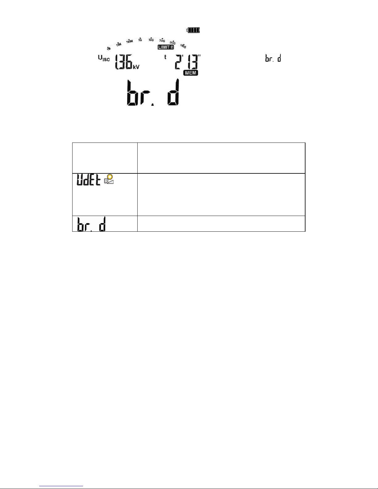
Use SET/SEL to display values of
leakage current IL.
After the measurement is completed or stopped, read the result. The
results of all completed measurements will be displayed (even
when the measurement was interrupted)
When the meter switched into
standby mode, the measurement
result may be recalled by pressing
ENTER.
Use and buttons to browse the measured values of
resistance and leakage current at specific time intervals.
Resistance R
ISO
value, measured
in time t=5’30’. Symbol indicates the selected time interval,
in which the resistance value was
recorded.
The value of leakage current IL
measured in time t=5’30’. Symbol
indicates the selected time
interval, in which the leakage current value was recorded.
Page 20
MIC-5001 OPERATING MANUAL
version 1.01
18
If the electric resistance strength
of the tested insulation is exceeded and the puncture occurs,
the main field of the display will
show message - breakdown.
Additional information displayed by the meter
NOISE!
Interference voltage occurs on the tested object. The
measurement is possible however it will be burdened
with additional uncertainty that is specified in the technical data.
, LED
is blinking in red
and two-tone
acoustic signal is
generated
Interference voltage exceeds the allowable value, the
measurement is blocked.
Breakdown - the tested object is damaged. The insulation has been pierced.
In case of RampTest measurement, the analogue filter FL is not active.
Page 21
MIC-5001 OPERATING MANUAL
version 1.01
19
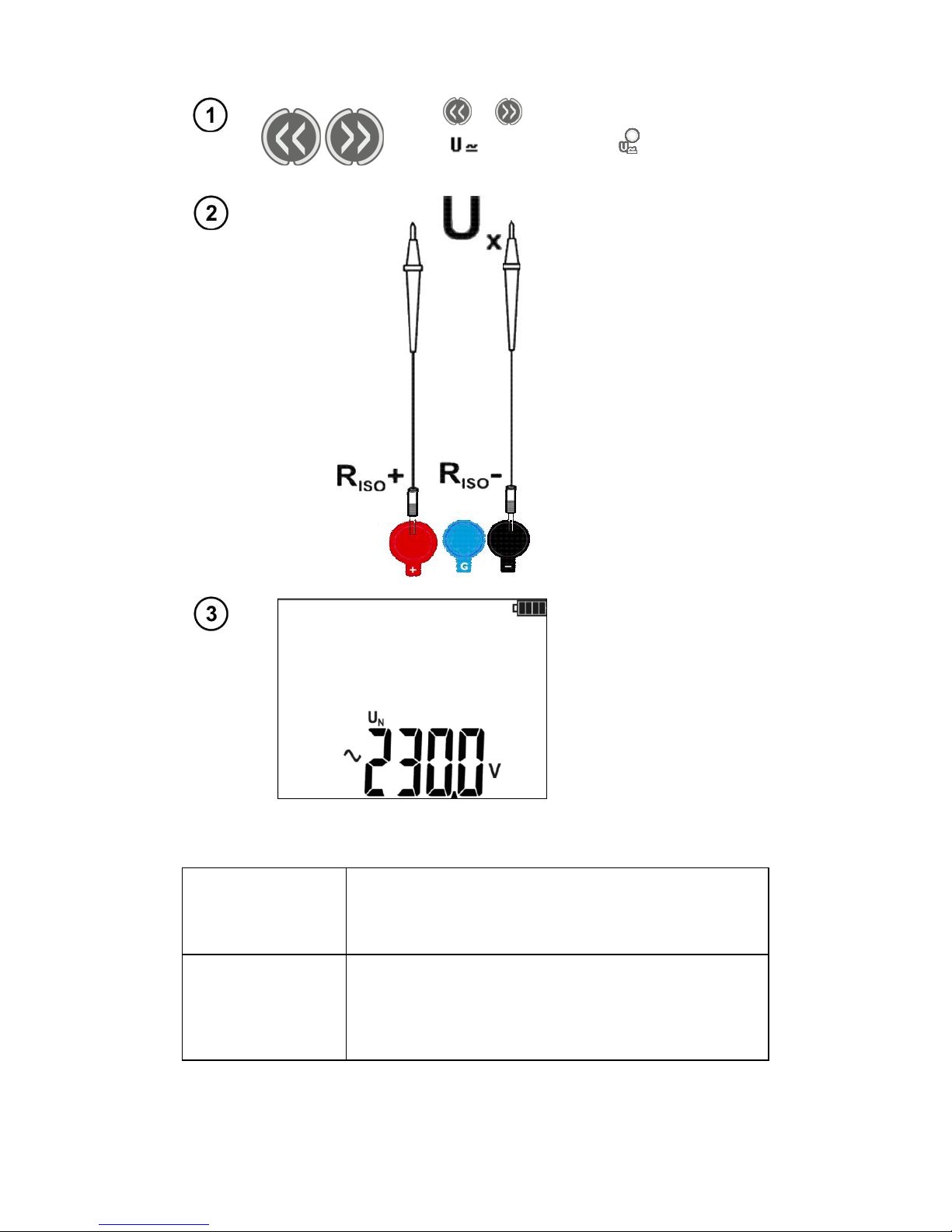
4.3 Voltage measurement
Use or buttons to enter the measurement (green LED is ON ). The meter is
in the voltage measurement mode.
Connect the meter to a
voltage source.
Measurement is performed in a continuous
manner.
Additional information displayed by the meter
>750V, LED is
blinking in red,
two-tone acoustic
signal is generated
Measuring range is exceeded. Voltage is higher than
acceptable. Immediately disconnect the test leads.
~
-
When AC voltage is detected, the device will display
symbol "~" ("wave") and when DC voltage is detected,
the device will display symbol "-" for negative polarity
or "nil" for positive polarity.
Page 22
MIC-5001 OPERATING MANUAL
version 1.01
20
5 Memory of measurement results
MIC-5001 meters have memory divided into 10 banks of 99 cells. Thanks to dynamic memory allocation, each of the memory cells can contain different quantity of single measurement results, depending on the needs. Optimal use of the memory can be ensured in this way. Each measurement result can be stored in a memory cell marked with a selected number and in a selected memory bank.
Thanks to this, the user of the meter can, at his/her option, assign memory cell numbers to individual
measurement points and the memory bank numbers to individual facilities. The user may also perform
measurements in any chosen sequence and repeat them without losing other data.
Memory of measurement results is not deleted when the meter is switched off. Thanks to this, the
data can be later read or sent to a computer. The number of a current memory cell or memory bank is
not changed either.
Note:
- Results of measurements performed for all measuring functions can be stored in one memory cell,
excluding U .
- After entering the measurement result, the ID number of the cell is automatically increased.
- It is recommended to delete the memory after reading the data or before performing a new series of
measurements that may be stored into the same memory cells as the previous ones.
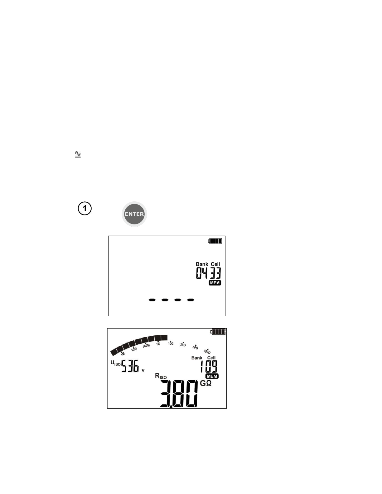
5.1 Storing the measurement results in the memory
After completing measurement
press ENTER.
The cell is empty.
The cell is partially
occupied by the same
type of result, which
is to be entered.
Page 23
MIC-5001 OPERATING MANUAL
version 1.01
21
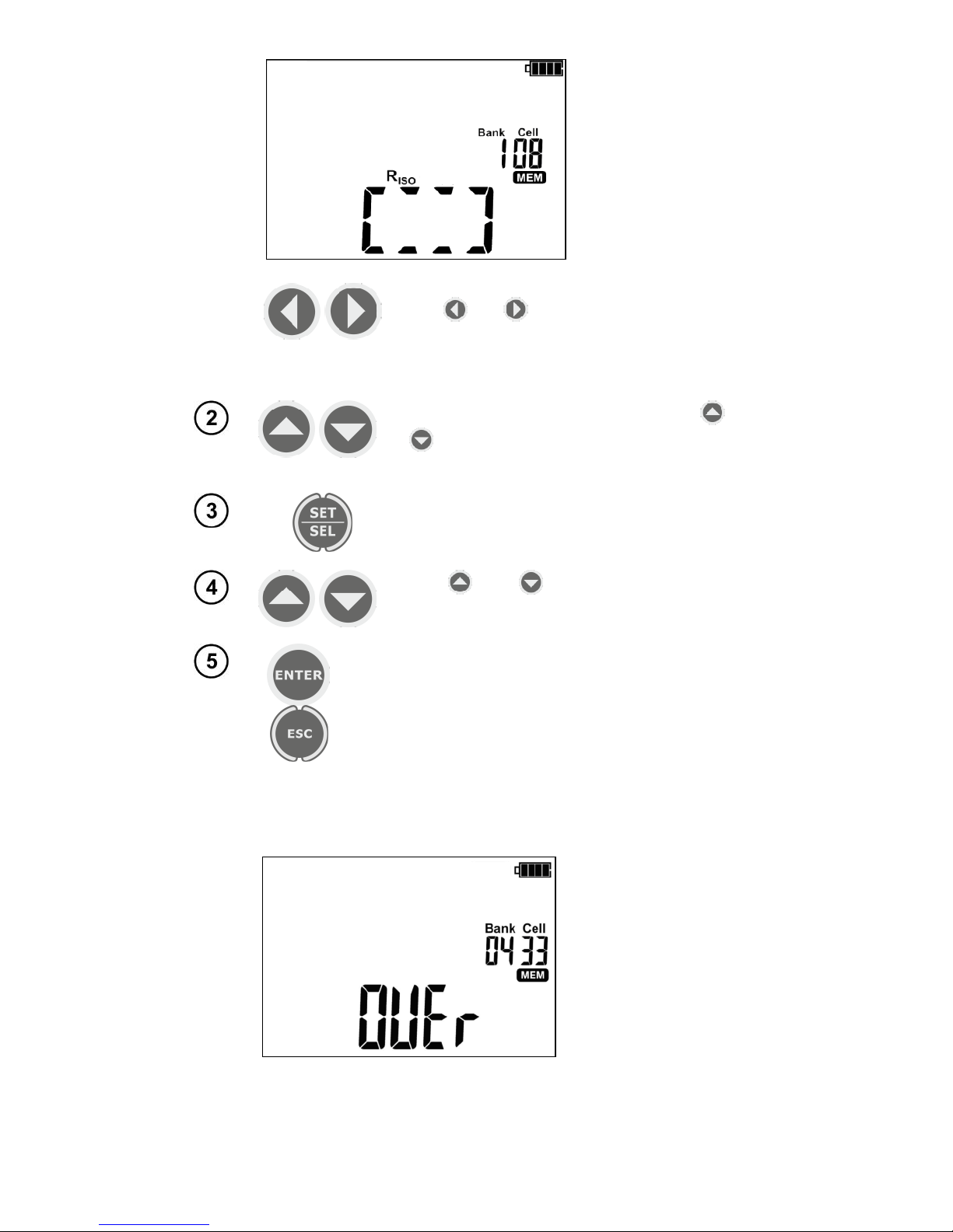
The cell is reserved.
Symbols (mnemonics) of stored values
are displayed.
Use and buttons to preview the results
stored in the selected cell.
To change the cell number or bank number:
When the cell number is flashing, use and
buttons to set the desired number of the
cell.
Press SET/SEL button – bank number is flashing.
Use and buttons to set the desired
number of the bank.
After selecting the desired bank and cell, press
ENTER button, to save the result in the memory. Recording is indicated by a triple beep.
Press ESC to return to the measurement screen
without saving.
If you try to store data in an occupied memory cell, the following
warning message will appear:
Page 24
MIC-5001 OPERATING MANUAL
version 1.01
22
or
Press ENTER, to overwrite the result
or ESC, to cancel and select other cell
or bank.
Note:
- After the measurement, its result is shown on the display until:
the measurement function is changed,
Auto-OFF function is activated,
the meter detects interference voltage> 50V,
one of the following operations is performed:
o ESC button is pressed to exit to the voltmeter,
o next measurement is performed,
o an entry into the memory is introduced.
- After exiting to the voltmeter by pressing ESC or after saving the results to the memory, the last result may be recalled by pressing ENTER.
- Complete set of results (main result and supplementary results) for a given measuring function and
preset measurement settings are stored in the memory.
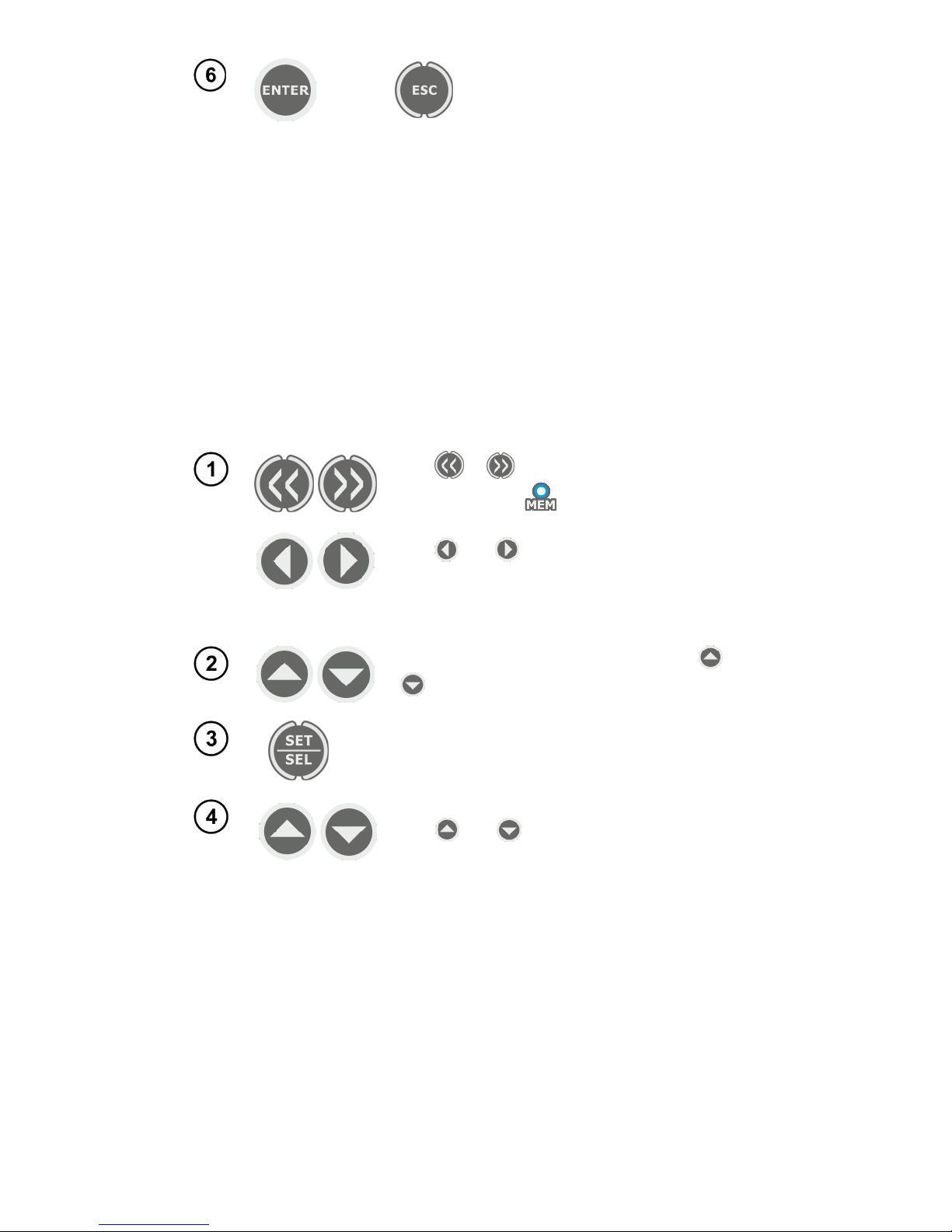
5.2 Viewing memory data
Use or to browse the memory: MEM
(blue LED is ON ).
Use and buttons to preview the results
stored in the selected cell.
To change the cell number or bank number:
When the cell number is flashing, use and
buttons to set the desired number of the cell.
Press SET/SEL button – bank number is flashing.
Use and buttons to set the desired number of the bank.
Note:
While viewing R
ISO
results, the field of timer / memory displays alternately bank and cell numbers
and the time in which the result was entered into memory. This applies to all R
ISO
and IL measure-
ments. Press ESC to immediately display the basic component of the result.
Page 25
MIC-5001 OPERATING MANUAL
version 1.01
23
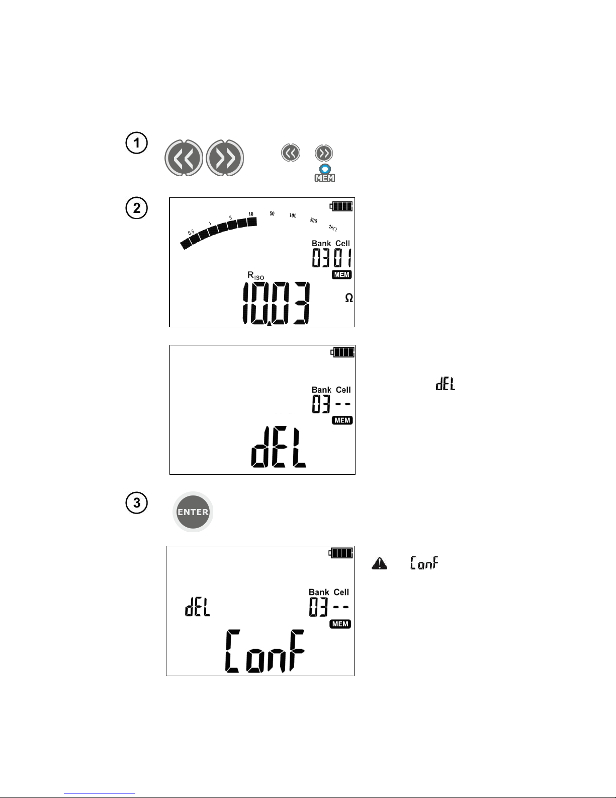
5.3 Deleting memory data
You can delete the entire memory or its individual banks.
5.3.1 Deleting bank data
Use or button to browse the memory:
MEM (LED is ON).
Set the bank number to
be deleted
acc. to section 4.2.
Set the cell number as
"--" (before "01")...
... and the cell number
will change into "--",
then symbol will be
displayed to indicate
the readiness for deleting.
Press ENTER button.
and symbols
appear, asking you to
confirm deletion.
Page 26
MIC-5001 OPERATING MANUAL
version 1.01
24
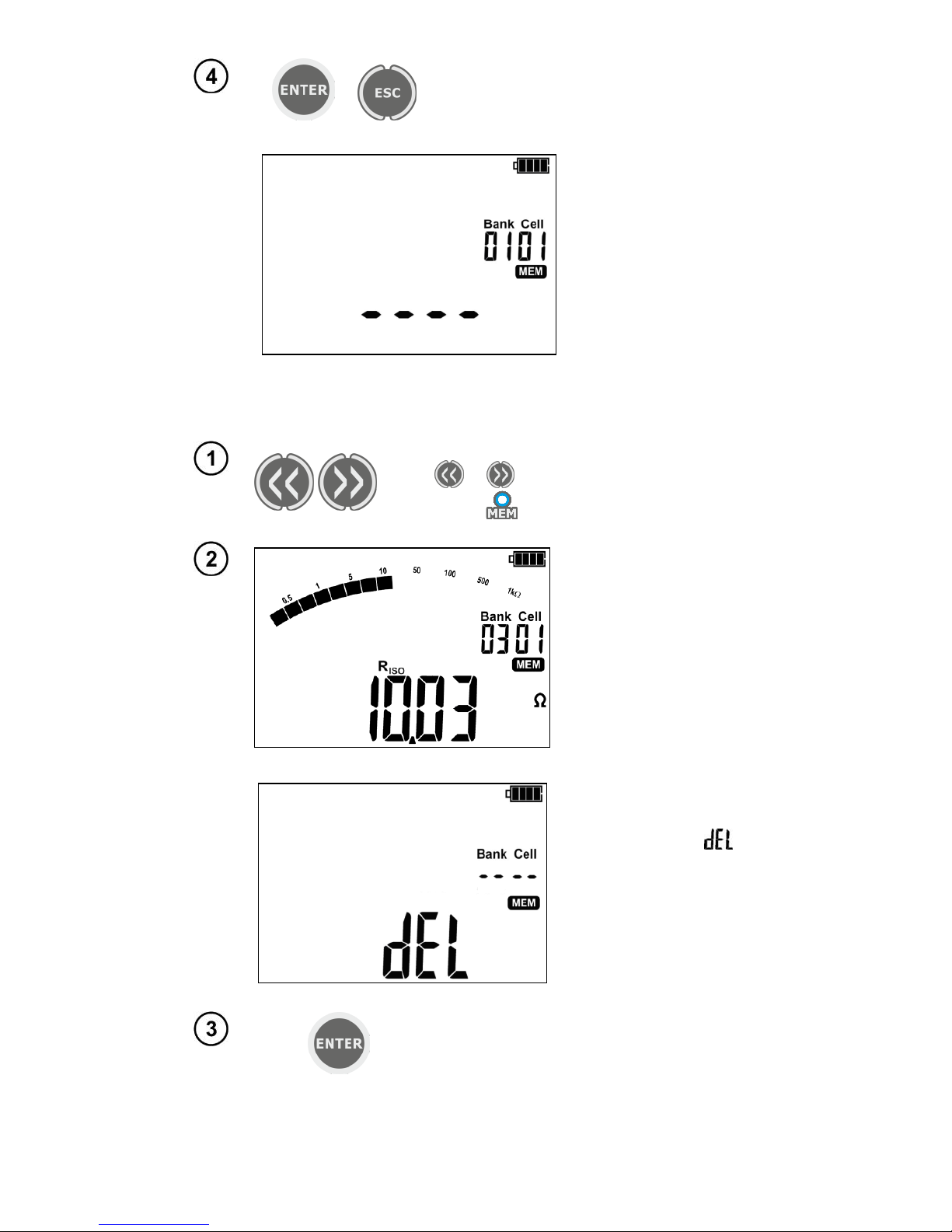
or
Press ENTER button again to delete the
selected bank.
After deleting the bank, the meter beeps
three times. Cancel by pressing ESC.
The contents of the bank has been deleted.
5.3.2 Deleting the whole memory
Use or button to browse the memory:
MEM (LED is ON).
Set the bank number s
"--" (before "01")...
… the bank number will
change into
"--", then symbol
will be displayed to indicate the readiness for
deleting the whole
memory.
Press ENTER button.
Page 27
MIC-5001 OPERATING MANUAL
version 1.01
25
and symbols
appear, asking you to
confirm deletion.
or
Press ENTER again.
After deleting the memory, the meter beeps
three times.
The entire contents of the memory has been deleted.
6 Data transmission
6.1 Computer connection accessories
In order to operate the meter with a PC, an USB cable and appropriate software are required. If
the required software has not been purchased with the meter, it may be downloaded from the manufacturer's website or purchased form the manufacturer or its authorised distributor.
The software may be used for many devices manufactured by SONEL S.A. which are equipped
with the USB interface or other (depending on the selected device).
Detailed information is available from the manufacturer and distributors.
6.2 Data transmission with USB joint
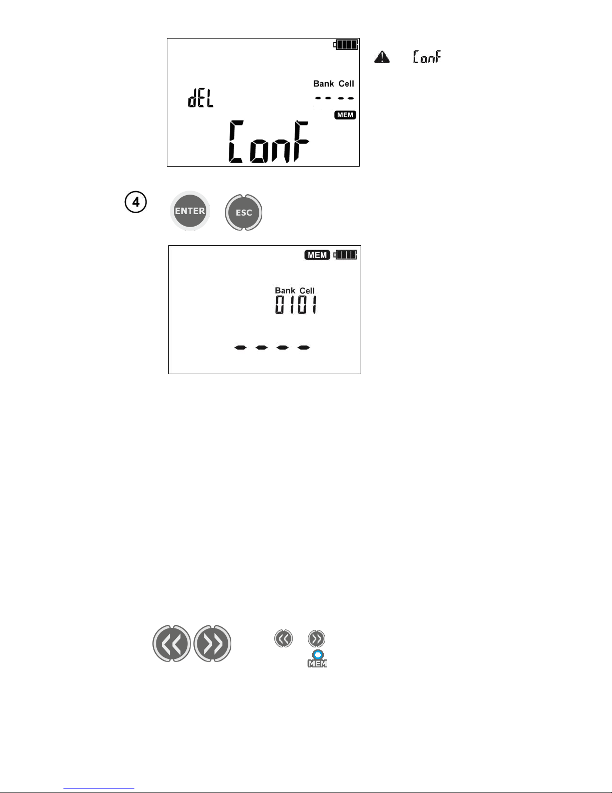
1.
Use or button to browse the memory:
MEM (LED is ON).
2. Connect the cable to the USB port of the computer and the USB socket of the meter. The meter will
displays the message:
Page 28
MIC-5001 OPERATING MANUAL
version 1.01
26
3. Start the program for communicating with the meter (processing results) and follow the commands
of the software.
7 Processing the measurement results
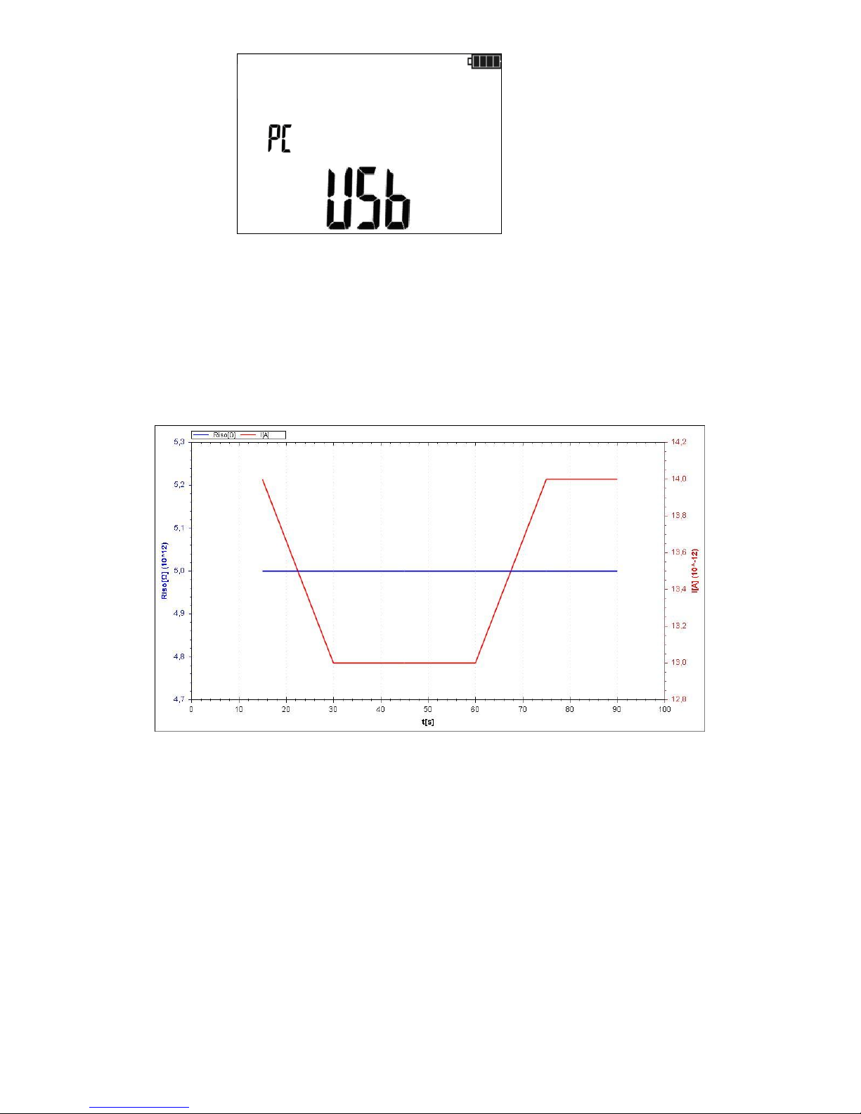
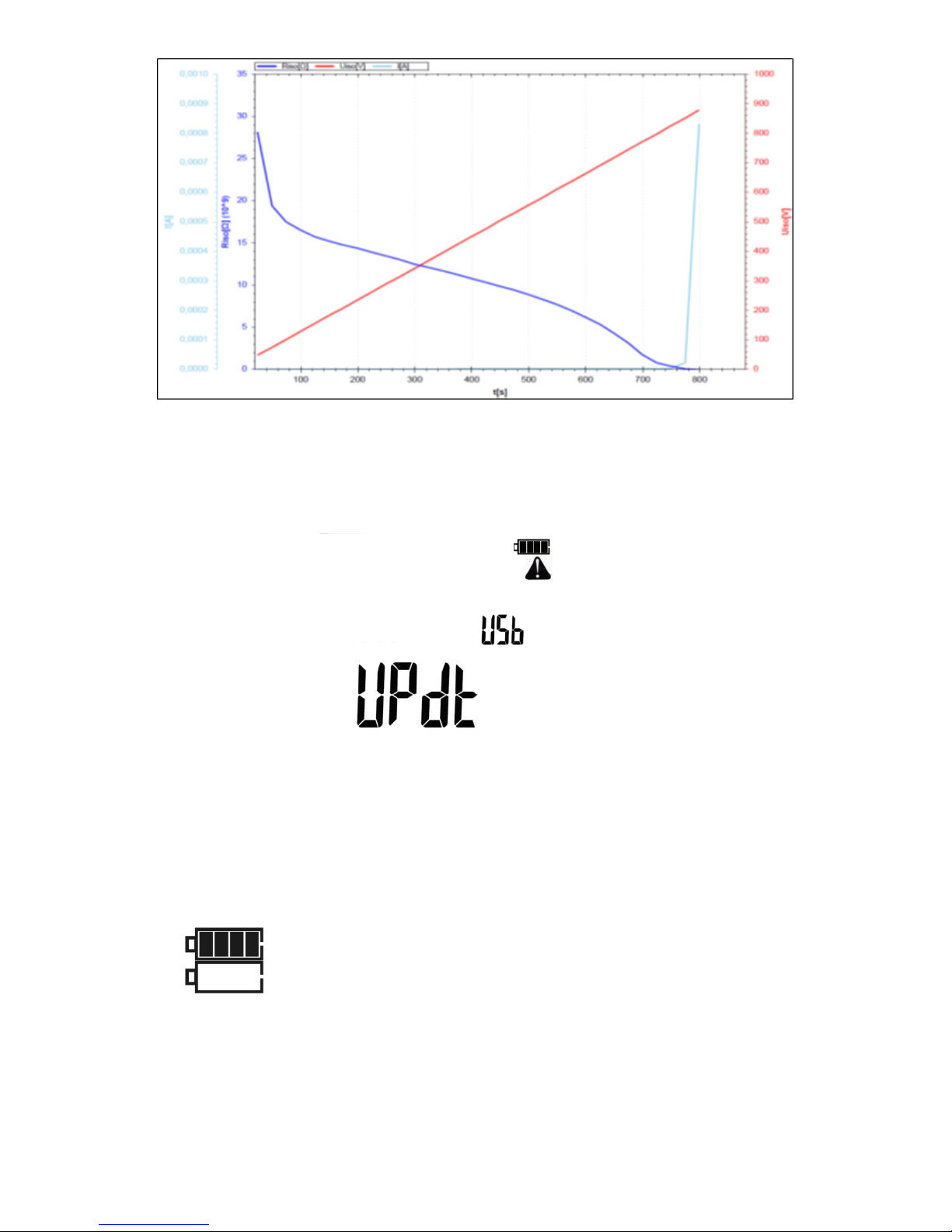
The measurement data recorded and stored in the meter may be browsed and analysed using
the SonelReader software. For Riso measurement, the previously defined time interval ChA, allows
the program user to delete the course of resistance and current as a function of time.
For a measurement with voltage increase method (RampTest), the user basing on performed
measurements, may analyse the characteristics of voltage, resistance and current as a function of
time.
When the insulation is not damaged, the prepared chart may be used to determine a hypothetical breakdown voltage of the insulation.
Page 29
MIC-5001 OPERATING MANUAL
version 1.01
27
8 Software updates
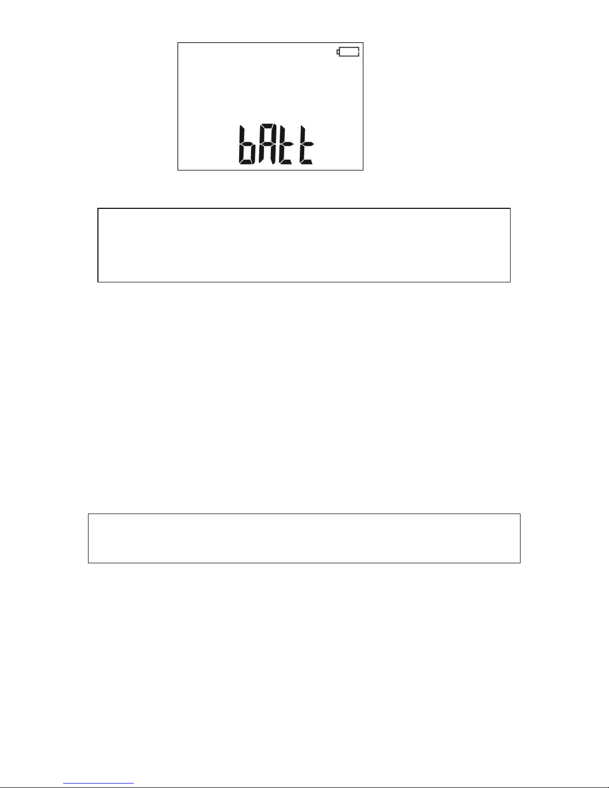
1. In accordance with the guidelines of Section 3 of this manual, enter the meter software update
mode: UPdt
2. Connect the cable to the USB port of the computer and the USB socket of the meter.
3. Start the program for updating the meter and follow the commands of the software.
9 Power supply
9.1 Monitoring the power supply voltage
The charge level of the battery pack is indicated by the symbol in the right upper corner of the dis-
play on a current basis:
The battery pack is charged.
The charge of battery pack is low. Only voltage measurement is
available.
No battery icon (when the charger is connected). The battery
pack is disconnected or damaged.
Page 30
MIC-5001 OPERATING MANUAL
version 1.01
28
The battery pack is fully discharged,
all measurements are blocked.
The meter switches off automatically after 5 sec.
9.2 Charging the rechargeable batteries
CAUTION!
MIC-5001 meter is powered from SONEL battery pack, which includes
NiMH 9.6 V batteries and it may be replaced only by the manufacturer's service
department.
Battery charger is installed inside the meter and cooperates only with the manufacturer’s re-
chargeable battery pack. The charger is powered by external power supply adapter. The device may
be also powered from the car cigarette lighter socket (12V only), using an optional charger.
Charging commences once the power supply has been connected to the meter regardless of the
fact whether the meter is on or off (only the charging mode is different - as described below). When
the meter is switched off - the charging process is indicated on the screen by displaying animated
symbol of battery being charged; when the meter is switched off - the charging is indicated by blinking
LED's of measurement functions (they blink consecutively in red).
Charging modes:
- the meter (user interface) is switched off: the battery pack is charged in "quick charging" mode - the
charging process takes approx. 4 hours. Completed charging is indicated by full battery symbol, FULL
message and beep. In order to fully turn the device off, unplug the power charger.
- the meter (user interface) is switched on: the battery pack is charged in "background charging" mode
- the charging may be longer than the charging process of the device which is switched off. Completed
charging is indicated by full battery symbol and beep. If the charging time exceeds 10 hours, the meter will automatically switch off for safety reasons.
In order to fully turn the device off, unplug the power charger and turn the meter off.
CAUTION!
Do not power the meter from sources other than those listed in this manual.
Note:
- Due to interferences in the mains, the process of battery pack charging may finish prematurely. When
charging time is too short, turn off the meter and start charging again.
Page 31

MIC-5001 OPERATING MANUAL
version 1.01
29
Additional information displayed by the meter
Signalling
Cause
Solution
Displayed message: Err ACU
Hi°C
Temperature of the battery pack is too high!
Wait until the battery pack is cool. Start
charging process again.
Displayed message: Err ACU
Lo°C
Temperature of the battery pack is too low.
Wait until the battery pack is warm
enough. Start charging process again.
Displayed message: Err ACU X
(where X is the number of error)
Emergency
Try to start the charging process again.
When powering the device from the
cigarette lighter socket, check whether
the socket supplies 12V voltage. If this
does not help, the battery pack may be
damaged - contact the manufacturer's
service.
No battery icon (when the
charger is connected)
The battery pack is disconnected or damaged.
Contact the manufacturer's service.
9.3 General principles regarding using Ni-MH rechargeable batteries
- Store the he rechargeable batteries (the meter) in a dry, cool and well ventilated place and protect
them from direct sunlight. The temperature of the environment in the case of prolonged storage should
not exceed 30°C. If the rechargeable batteries are stored for a long time in a high temperature, then
the occurring chemical processes may reduce their lifetime.
- Rechargeable batteries NiMH usually lasts for 500-1000 charging cycles. The rechargeable batteries
reach their maximum capacity after being formatted (2-3 charge and discharge cycles). The most important factor which influences the lifetime of rechargeable batteries is the level of their discharge. The
deeper the discharge level of the batteries, the shorter their lifetime.
- The memory effect is limited in the case of NiMH batteries. These batteries may be charged at any
point with no serious consequences. However, it is recommended to discharge them completely every
few cycles.
- During storage of Ni-MH rechargeable batteries they are discharged at the rate of approximately 20%
per month. Keeping rechargeable batteries at high temperatures may accelerate this process even
100%. In order to prevent excessive discharge of rechargeable batteries, after which it would be necessary to format them, it is recommended to charge them from time to time (even if they are not used).
- Modern fast chargers detect both too low and too high a temperature of the battery pack and react to
the situation adequately. Too low temperature should prevent starting the process of charging, which
might irreparably damage rechargeable batteries. An increase of the temperature of the rechargeable
batteries is a signal to stop charging and is a typical phenomenon. However charging at a high ambient temperature apart from reducing batteries' lifetime causes an accelerated increase of their temperature and the result is that the batteries are not charged to their full capacity.
- Please note that when the batteries are charged with a fast-charger they are charged only to approx.
80% of their capacity - better results can be achieved by continuing charging: the charger enters trickle-charging mode and during the next few hours batteries are charged to their full capacity.
- Do not charge or use the batteries in extreme temperatures. Extreme temperatures reduce the lifetime of batteries and rechargeable batteries . Avoid placing devices powered by rechargeable batteries in very hot environments. The nominal working temperature must be absolutely observed.
Page 32

MIC-5001 OPERATING MANUAL
version 1.01
30
10 Cleaning and maintenance
CAUTION!
Use only the maintenance methods specified by the manufacturer in this manual.
The casing of the meter may be cleaned with a soft, damp cloth using all-purpose detergents. Do
not use any solvents or cleaning agents which might scratch the casing (powders, pastes, etc.).
Clean the probe with water and dry it. Before the probe is stored for a prolonged period of time it is
recommended to grease it with any machine lubricant.
The reels and test leads should be cleaned with water and detergents, and then dried.
The electronic system of the meter does not require maintenance.
11 Storage
In the case of storage of the device, the following recommendations must be observed:
Disconnect all the test leads from the meter.
Clean the meter and all its accessories thoroughly.
Wind the long test leads onto the reels.
In order to prevent a total discharge of the battery pack in the case of a prolonged storage, charge
it from time to time.
12 Dismantling and Disposal
Worn-out electric and electronic equipment should be gathered selectively, i.e. it must not be
placed with waste of another kind.
Worn-out electronic equipment should be sent to a collection point in accordance with the law of
waste electrical and electronic equipment.
Before the equipment is sent to a collection point, do not dismantle any elements.
Observe local regulations concerning disposal of packages, waste batteries and accumulators.
Page 33
MIC-5001 OPERATING MANUAL
version 1.01
31
13 Technical specifications
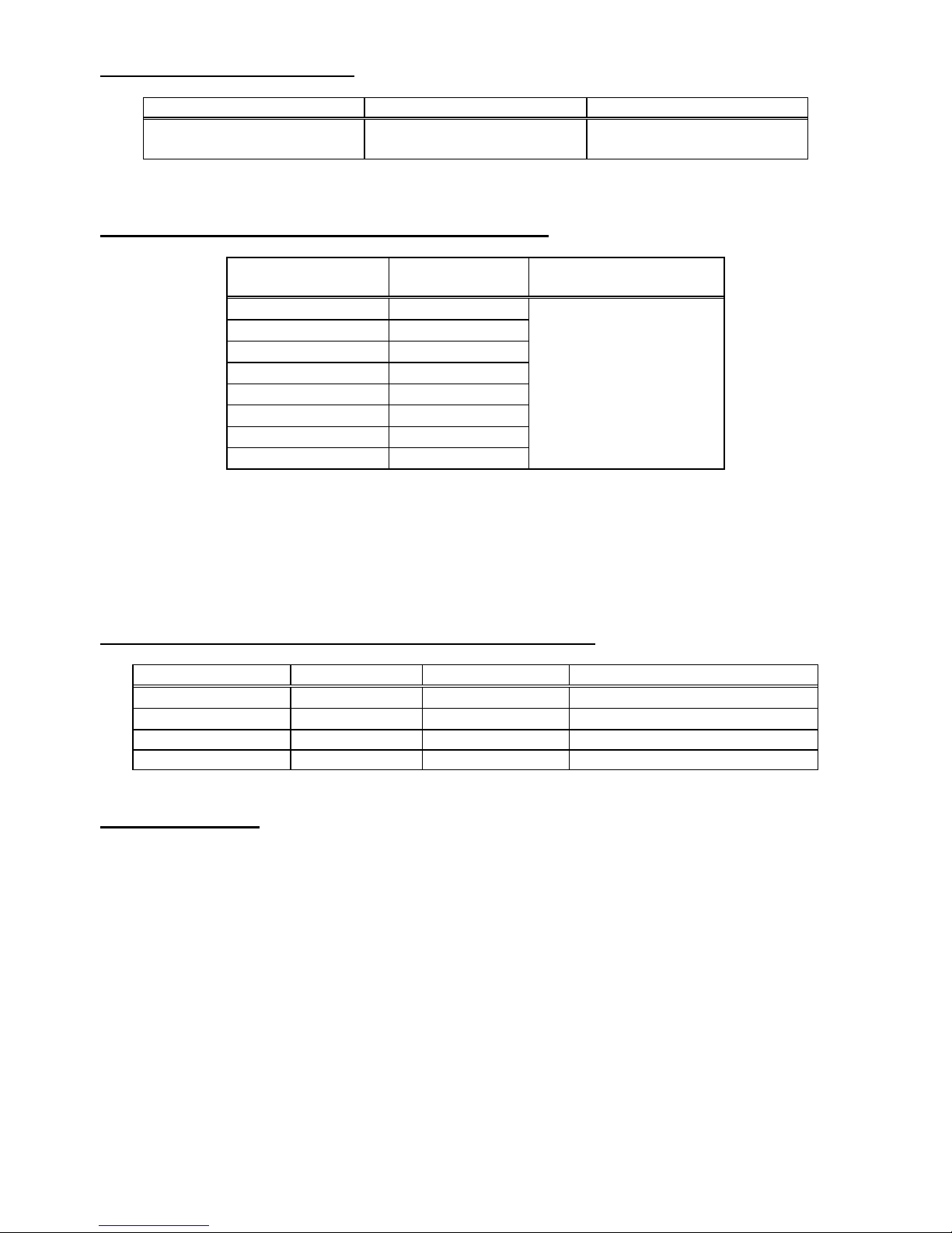
13.1 Basic data
Abbreviation "m.v." used in the specification of basic uncertainty means standard measured value
AC / DC voltage measurement
Display range
Resolution
Basic uncertainty
0…299,9 V
0.1 V
(3 % m.v. + 2 digits)
300…750 V
1 V
Frequency range for AC: 45 Hz...65 Hz
Measurement of insulation resistance
Measuring range according to IEC 61557-2: R
ISOmin
= U
ISOnom/IISOnom
…1000 G (I
ISOnom
= 1 mA)
Double-lead measurement
Display range
Resolution
Basic uncertainty
0.0 k...999.9 k
0.1 k
(3 % m.v. + 20 digits)
1.000 M...9.999 M
0.001 M
10.00 M...99.99 M
0.01 M
100.0 M...999.9 M
0.1 M
1.000 G...9.999 G
0.001 G
10.00 G...99.99 G
0.01 G
100.0 G...999.9 G
0.1 G
1.000T….5.000 T
1 G
±(4% m.v. + 50 digits)
When the range is exceeded, the device displays ">xxxxGΩ" (where xxxx is the limit value for
the selected range).
Approximate maximum values of the measured resistance, depending on the test voltage, are
presented in the table below.
Voltage
Test range
up to 100 V
50 G
200 V…400 V
100 G
500 V…900 V
250 G
1000 V…2400 V
500 G
2500 V
1000 G
5000 V
5000 G
Note: For insulation resistance below R
ISOmin
there is no accuracy specified because the meter
works with the adjustable current limit in accordance with the following formula:
ISOnom
nomISO
ISO
I
U
R min
where:
R
ISOmin
– minimum insulation resistance measured without limiting the converter current
U
ISOnom
– nominal test voltage
I
ISOnom
– nominal inverter current (1 mA)
Max. short-circuit current: ISC = 1.4 mA ±15 %
Page 34
MIC-5001 OPERATING MANUAL
version 1.01
32
Measurement of leakage current
Display range
Resolution
Basic uncertainty
0…ILmax
m, μ, n
Calculated basing on re-
sistance measurements
ILmax – maximum current at short circuit of leads,
resolution and units result from the measurement range of individual insulation resistance.
Measurement of insulation resistance in RampTest mode
Range
Resolution
Basic
uncertainty
0.0…999.9 k
0.1 k
(5% m.v. + 40 digits)
1.000…9.999 M
0.001 M
10.00…99.99 M
0.01 M
100.0…999.9 M
0.1 M
1.000…9.999 G
0.001 G
10.00…99.99 G
0.01 G
100.0…999.9 G
0.1 G
1.000…4.999 T
0.001 T
Table for the measuring voltage increase times t5 V/s,
For times of measuring voltage increase t>5 V/s, the measurement error of the insulation re-
sistance is not specified,
For times of measuring voltage increase t>50 V/s, the measurement result of the insulation
resistance is not displayed,
Measurement possible for the object capacity not exceeding 1 uF.
The measurement of breakdown voltage in Ramp Test function
Range
Resolution
Selected U
ISO
Basic uncertainty
25,0 V …99,0 V
0.1 V
600 V
± 5% m.v. ± 10 digits
100 V … 600 V
1 V
600 V
±5% m.v. ± 4 digits
25 V … 999 V
1 V
>600 V
5% m.v. + 5 digits
1.00 kV … 5.00 kV
10V
>600 V
±5% m.v. ± 4 digits
Measurement possible for the object capacity not exceeding 1 uF.
Other technical data
a) type of insulation ........................................................... double, acc. to EN 61010-1 and EN 61557
b) measurement category ............................................. III 600 V (IV 300 V) according to EN 61010-1
c) degree of housing protection acc. to EN 60529......................................................................... IP65
d) power supply of the meter................................................... SONEL battery pack, NiMH 9.6 V 2 Ah
e) Battery charging time .................................................................................... usually 4 h, max. 10 h
f) parameters of the external power supply adapter ................................ 90 V…264 V, 50 Hz…60 Hz
g) dimensions .......................................................................................... 200 mm x 150 mm x 75 mm
h) meter weight ............................................................................................................. approx. 1.0 kg
i) allowable batter pack charging temperatures in mode 500mA ................................ +10 °C...+40 °C
j) temperatures at which the charging process is interrupted ................................ <0 °C and ≥ +50 °C
k) operating temperature range with external power supply adapter ...................... <0 °C and ≥ +50 °C
l) storage temperature .................................................................................................-20C...+60C
m) operating temperature ..............................................................................................-15C...+40C
n) humidity ....................................................................................................................... 20 %...80 %
o) reference temperature ................................................................................................ +23C ± 2C
Page 35

MIC-5001 OPERATING MANUAL
version 1.01
33
p) reference humidity ................................................................................................ ....... 40 %...60 %
q) altitude (above sea level) .................................................................................................. <2000 m
r) number of measurements R
ISO
acc. to PN-EN 61557-2 ................................ .................. approx. 800
s) modular ................................................................................................................................... LCD
t) memory of measurement results ....................................................................................... 990 cells
u) data transmission .................................................................................................. USB connection
v) quality standard ... design, construction and manufacturing are ISO 9001, ISO 14001, PN-N-18001
compliant
w) the device meets the requirements of EN 61557 standard
x) the product meets EMC requirements (immunity for industrial environment) according to the fol-
lowing standards ..............................................................................................................................
...................................................................................... EN 61326-1:2013 and EN 61326-2-2:2013
13.2 Additional uncertainties according to IEC 61557-2 (R
ISO
)
Data on additional uncertainties are useful mainly when the meter is used in non-standard condi-
tions and for metrological laboratories for the purpose of calibration.
Significant parameter
Designation
Additional uncertainty
Position
E
1
0 %
Supply voltage
E
2
0% (BAT is not lit)
Temperature 0C...35 °C
E
3
0.1 %/ºC
14 Accessories
14.1 Standard Equipment
The standard set of equipment supplied by the manufacturer includes:
MIC-5001 meter – WMPLMIC5001
shielded wire 1.8 m, 5 kV, ended with banana plugs, black (cat. IV 1 kV) - WAPRZ1X8BLBB
shielded wire 1.8 m, 5 kV, ended with banana plugs, red (cat. IV 1 kV) – WAPRZ1X8REBB
shielded wire 1.8 m, 5 kV, ended with banana plugs, blue (cat. IV 1 kV) – WAPRZ1X8BUBB
crocodile clip 5.5 kV black (cat. IV 1 kV) – WAKROBL32K07
crocodile clip 5.5 kV red (cat. IV 1 kV) – WAKRORE32K07
crocodile clip 5.5 kV blue (cat. IV 1 kV) – WAKROBU32K07
probe 5 kV, red (cat. IV 1 kV), – WASONREOGB2
probe 5 kV, black (cat. IV 1 kV) – WASONBLOGB2
external adapter for battery pack charging – WAZASZ7
USB cable – WAPRZUSB
case – WAFUTM8
calibration certificate
operating manual
guarantee card.
Page 36
MIC-5001 OPERATING MANUAL
version 1.01
34
14.2 Optional accessories
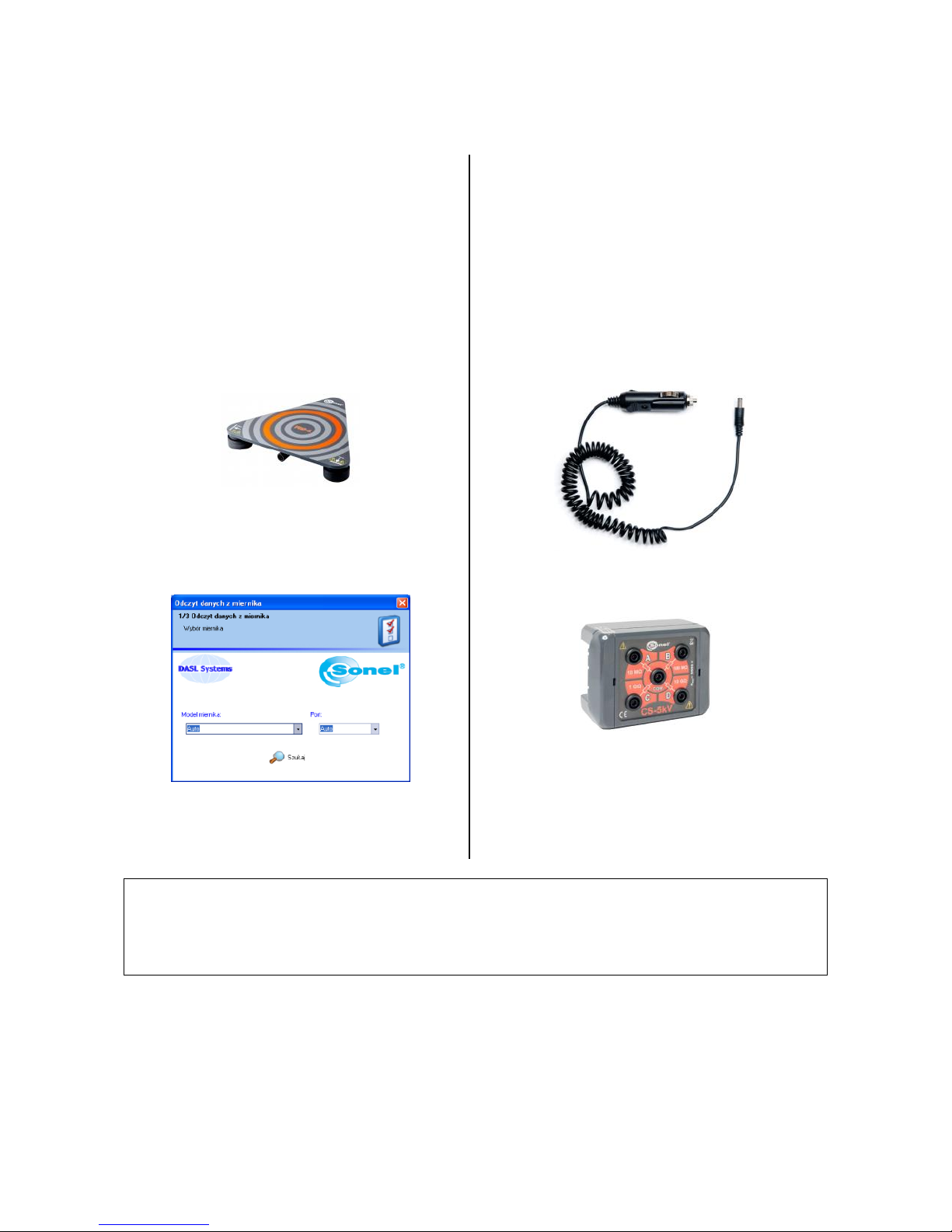
Additionally, the following items that are not included in the scope of standard equipment
can be purchased from the manufacturer or the distributors:
WAPRZ005BLBBE5K
5 m shielded cable, black, cat. IV 1000 V
WAPRZ005REBB5K
5kV cable, 5m, red, with banana plugs
WAPRZ005BUBB5K
5kV cable, 5m, blue, terminated with bana-
na plugs
WASONPRS1PL
probe for measuring the resistance of the
floors and walls PRS-1
WAPROSONPE5
"SONEL Pomiary Elektryczne" (SONEL
Electrical Measurements) - software for
generating measurement reports
WAPRZ010BLBBE5K
10 m shielded cable, black, cat. IV 1000 V
WAPRZ010REBB5K
5kV cable, 10 m, red, with banana plugs
WAPRZ010BUBB5K
5kV cable, 10m, blue terminated with bana-
na plugs
WAPRZLAD12SAM
cable for charging the battery pack from
the car cigarette lighter socket (12V)
WAADACS5KV
calibration box CS-5 kV
LSWPLMIC5001
calibration certificate
Note
The software is supported by the following systems: Windows XP (Service Pack 2) or
later.
Page 37
MIC-5001 OPERATING MANUAL
version 1.01
35
15 Manufacturer
The manufacturer of the device and provider of guarantee and post-guarantee service:
SONEL S.A.
ul. Wokulskiego 11
58-100 Świdnica
Poland
tel. +48 74 858 38 60
fax +48 74 858 38 09
E-mail: [email protected]
Web page: www.sonel.pl
Note:
Service repairs must be performed only by the manufacturer.
Page 38

MIC-5001 OPERATING MANUAL
version 1.01
36
16 Laboratory services
Research and Calibration Laboratory of SONEL SA offers calibration of the following in-
struments used for electrical/non-electrical measurements:
- meters for electrical protective measurements: insulation resistance, impedance and resistance of short-circuit loops, earthing resistances and earth resistivity, RCD parameters
and multi-functional meters that perform the above functions,
- electrical safety meters,
- multimeters,
- power quality analysers,
- meters for measuring low resistance values,
- infra-red cameras,
- pyrometers,
- luxmeters.
In addition, the Laboratory performs voltage, current and resistance calibration.
A calibration certificate is a document confirming compliance of parameters declared by the
manufacturer of tested device with national standards, specifying the measurement uncertainty.
Pursuant to standard EN ISO 10012:2003 "Measurement management systems — Require-
ments for measurement processes and measuring equipment", SONEL S.A. recommends for
its instruments to be periodically tested, observing the interval of 13 months.
For new devices with calibration certificates, the next metrological inspection (calibration) is
recommended within 13 months from the date of purchase, but not later than 19 months from
the date of manufacture.
Note:
In case of instruments used for tests related to the protection against electric shock,
the person performing measurements should have complete confidence in the effi
ciency of operated apparatus. Measurements carried out with malfunctioning meter
may cause wrong assessment of tested equipment in terms of its protection features
Page 39

Page 40

 Loading...