

Page 1
Page 2
Page 3

OPERATING
MANUAL
INSULATION
RESISTANCE
METER
MIC-2
SONEL S. A.
ul. Wokulskiego 11
58-100 Świdnica
Version 1.8 21.02.2017
Page 4

We appreciate your having purchased our insulation resistance meter. The MIC-2 meter is a modern measuring device, which is easy and safe to
use. Please acquaint yourself with the present
manual in order to avoid measuring errors and
prevent possible problems related to operation of
the meter.
Page 5

3
TABLE OF CONTENTS
Attention:
The present operating manual applies solely to
the meters it has been attached to.
1 SAFETY ............................................... 4
2 MEASUREMENTS ............................. 5
2.1 INSULATION RESISTANCE
MEASUREMENT ................................. 5
2.2 CONNECTION RESISTANCE
MEASUREMENT ................................. 8
2.3 VOLTAGE MEASUREMENTS ............... 9
3 SOFTWARE VERSION AND
DESIGN DISPLAY ........................... 10
4 POWER SUPPLY OF THE
METER .............................................. 10
4.1 MONITORING OF THE POWER SUPPLY
VOLTAGE ........................................ 10
4.2 REPLACEMENT OF BATTERIES
(ACCUMULATORS) .......................... 11
5 CLEANING AND
MAINTENANCE .............................. 12
6 STORAGE ......................................... 12
7 DISMANTLING AND
UTILIZATION .................................. 12
8 TECHNICAL DATA ......................... 12
8.1 BASIC DATA .................................... 12
8.2 AUXILIARY DATA ........................... 14
9 ACCESSORIES ................................. 14
9.1 STANDARD ACCESSORIES ................ 14
9.2 OPTIONAL ACCESSORIES ................. 15
10 MANUFACTURER........................... 15
OPERATING MANUAL MIC-2 ver. 1.8
Page 6

4
Voltage exceeding 600V connected to the meter
may result in its damage.
1 Safety
The MIC-2 meter has been designed to realise
measurements whose results determine the safety
conditions of the installation. Therefore, in order to
provide conditions for correct operation and the
correctness of the obtained results, the following
recommendations must be observed:
Before you proceed to operate the meter, ac-
quaint yourself thoroughly with the present
manual and observe the safety regulations and
specifications determined by the producer.
The MIC-2 meter has been designed for the
purpose of insulation resistance and connec-
tion resistance measurements, as well as di-
rect and alternative voltage measurement. Any
other application than those specified in the
present manual may result in a damage to the
device and constitute a source of danger for
the user.
The device must be operated solely by appro-
priately qualified personnel with relevant certif-
icates that entitle them to realise measure-
ments of electric installation. Operation of the
meter realised by unauthorised personnel may
result in damage to the device and constitute a
source of danger for the user.
The device must not be applied to the network
and equipment within premises of special con-
ditions, e.g. in a dangerous atmosphere with
regard to explosion or fire.
It is unacceptable to operate the following:
A damaged meter which is completely or
partially out of order,
A meter with damaged cable insulation,
A meter stored for an excessive period of
time in disadvantageous conditions (e.g.
excessive humidity). If the meter has been
transferred from a cool to a warm environment of a high level of relative humidity, do not realise measurements until the
meter has been warmed up to the ambient temperature (approximately 30
minutes).
Before proceeding to a connection resistance
and insulation resistance measurement, make
sure the object under investigation has been
disconnected from the power supply voltage.
OPERATING MANUAL MIC-2 ver. 1.8
Page 7
5
During an insulation resistance measurement,
it is unacceptable to disconnect the cables
from the object under investigation before the
measurement has concluded; otherwise the
capacity of the object will not be discharged,
what gives rise to a danger of electric shock.
Do not operate a meter with an open or incor-
rectly closed battery (accumulator) compartment or power it from other sources than those
specified in the present manual.
The meter’s inputs are electronically protected
from power surge up to 660V for 30 seconds.
Repairs may be realised solely by an author-
ised service point.
The device complies with the following stand-
ards: PN-EN 61010-1 and PN-EN 61557.
2 Measurements
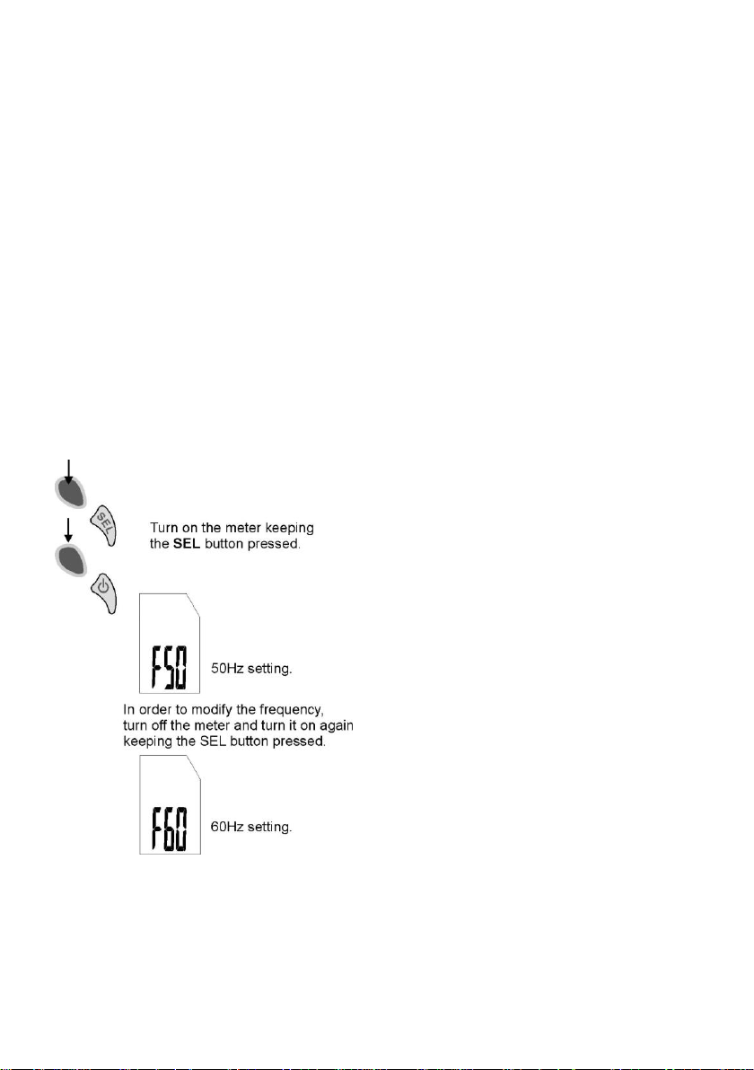
In order to effectively eliminate interferences,
before the initial measurements it is recommended
to set the frequency of the power network for the
given area (50Hz or 60Hz). In order to do so:
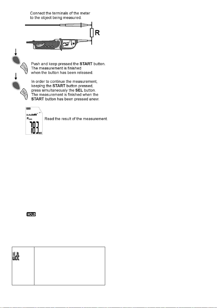
2.1 Insulation resistance measurement
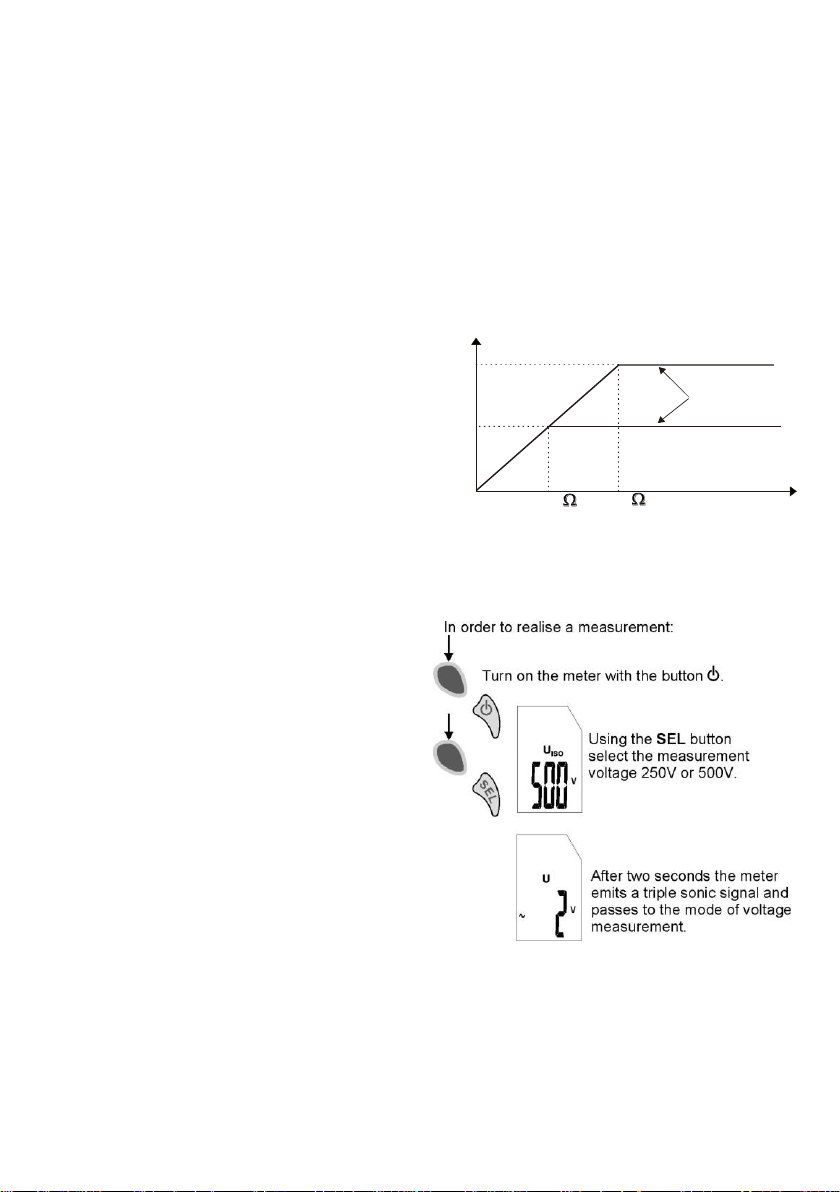
The device measures the insulation resistance
providing a test voltage U to the tested insulation
RX and measuring flowing current I at the side of
the R
Calculating the insulation resistance value, the me-
probe, and measured at the R
ISO-
OPERATING MANUAL MIC-2 ver. 1.8
ISO+
input.
Page 8
6
ter uses the technical insulation measurement
Proper
measurements
Insulation
resistance Rx
Measurement voltage
500V
500k
C
u
r
r
e
n
t
l
i
m
i
t
a
t
i
o
n
s
t
a
t
u
s
250V
250k
method (RX=U/I). The measurement voltage is selected between the two following values: 250V or
500V.
The level of the output current of the converter
is 1 mA. Activation of the current limitation is signalled by means of a continuous sonic alarm. The
result of the measurement is then correct, but at
the measurement terminals there is a measurement voltage which is lower than the one adjusted
before the measurement. The current limitation
may occur particularly often in the first stage of the
measurement due to the process of charging of the
capacity of the measured object.
The actual measurement voltage as the
function of the measured insulation resistance
RX (for the maximum measurement voltage).
OPERATING MANUAL MIC-2 ver. 1.8
Page 9
7
and a
continuous
double
tone sonic
signal
The measured object is under a voltage exceeding 20V. The measurement is blocked. During 5s a double
tone sonic signal is generated, and
then the meter displays the voltage of
the object. Disconnect the meter
from the object (both terminals)
immediately.
Remarks
- During the measurement cycle, the buzzer emits
a short single signal every five seconds, so it is
possible to record the chronological characteristics
of the resistance of the insulation under investigation.
- During measurements the AUTO-OFF is not active.
- In the mode of voltage measurement the AUTOOFF countdown starts anew each time the voltage
is changed by more than 5V.
- Once a measurement has been concluded, the
last result is shown on the display along with the
symbol . The last result of the measurement
disappears if there is a voltage exceeding 20V at
the measurement terminals.
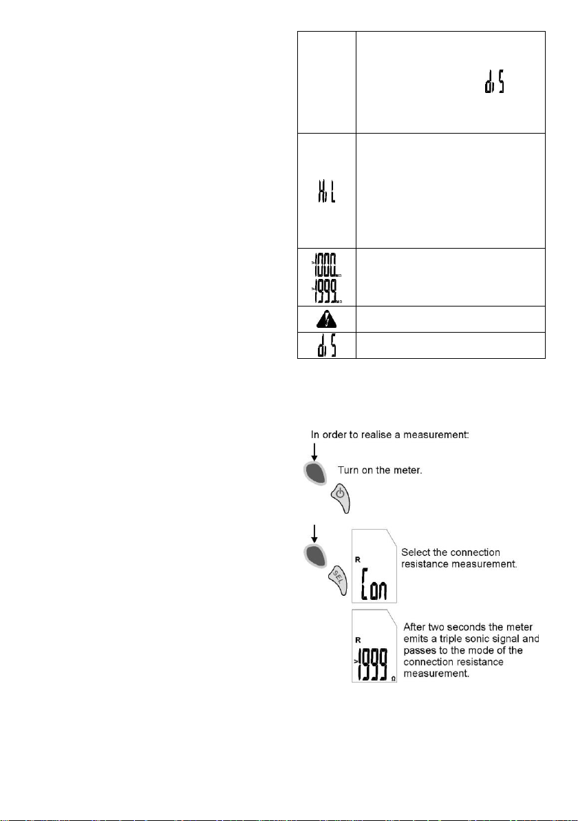
Additional information displayed by the
meter
OPERATING MANUAL MIC-2 ver. 1.8
Page 10
8
There may be an attempt to discharge the object before the measurement, it will be signalled by means
of the displayed symbol . An attempt to discharge is undertaken if
the voltage exceeds 20V, but is lower
than 100V.
The insulation resistance is too low,
the measurement is finished. The
symbol is displayed if after 10 seconds from the moment the START
button is pushed, the measurement
voltage has not reached the adjusted
value, and also if during the measurement the insulation is punched
through.
The measurement range has been
exceeded.
A warning regarding a high voltage at
the terminals of the meter.
The object is discharged.
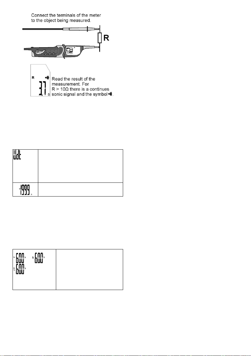
2.2 Connection resistance
measurement
OPERATING MANUAL MIC-2 ver. 1.8
Page 11
9
and a
continuous
double
tone sonic
signal
The measured object is under a voltage exceeding +7V, lower than -1V
(with regard to R
ISO
-) or exceeding 5V
AC. The measurement is blocked.
Disconnect the meter from the object (both terminals) immediately.
The measurement range has been exceeded.
or or
and a continuous double
tone sonic signal
The measured object is under
a voltage exceeding 600V
(positive, negative or alternate). Disconnect the meter
from the object (both terminals) immediately.
Comments
- The AUTO-OFF countdown starts anew each
time the resistance is modified by at least 200Ω.
Additional information displayed by the
meter
2.3 Voltage measurements
The meter measures the voltage if the U
voltages have been selected (without pressing the
START button).
Additional information displayed by the
meter
ISO
OPERATING MANUAL MIC-2 ver. 1.8
Page 12
10
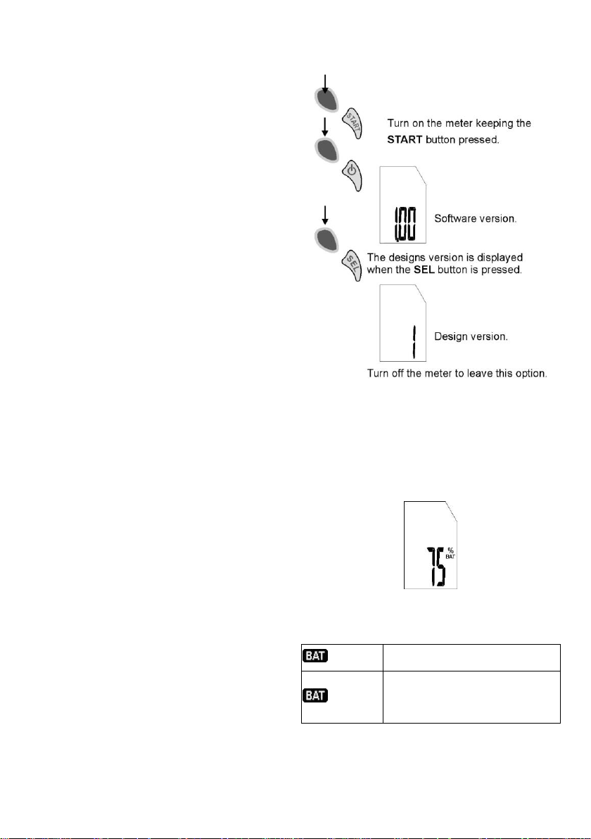
3 Software version and design
flashing
The charge of the batteries (accumulators) is below 25%.
constant
The charge of the batteries (accumulators) precludes measurements, except for measurements
of the voltage.
display
4 Power supply of the meter
4.1 Monitoring of the power
supply voltage
After the meter is turned on, the level of batteries or accumulators (rechargeable batteries) is displayed for 2 seconds (100%, 75%, 50%, and 25%).
Additional information displayed by the
meter
OPERATING MANUAL MIC-2 ver. 1.8
Page 13
11
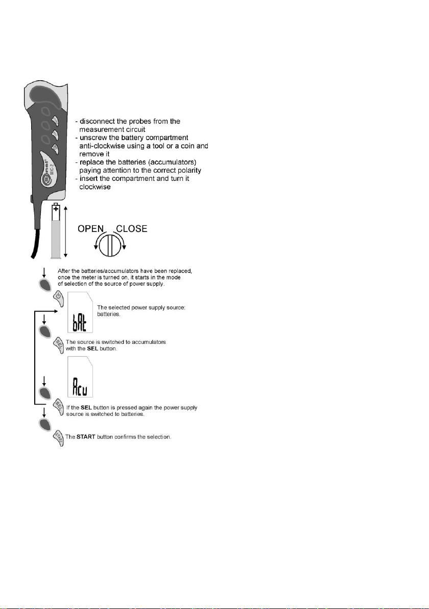
4.2 Replacement of batteries
(accumulators)
In order to replace the batteries (accumulators)
realise the following actions:
Remarks
- After the batteries/accumulators have been re-
placed you must select the kind of power supply,
since it is necessary to ensure the correctness of
the indication of the level of charge (the characteristics of battery and accumulator discharging vary).
- After the batteries have been replaced, when the
meter is off there may be no question regarding the
type of cells. Then remove the cells when the meter is on and insert them anew.
OPERATING MANUAL MIC-2 ver. 1.8
Page 14

12
- In the case the batteries leak inside the compart-
Displayed
range
Resolution
Intrinsic uncertainty
0…600V
1V
±(3% m.v. + 2 digits)
ment, the meter must be serviced.
- Accumulators must be charged in an external
charger.
5 Cleaning and maintenance
The casing of the meter may be cleaned with a
soft, damp cloth using all-purpose detergents. Do
not use any solvents or cleaning agents which
might scratch the casing (powders, pastes, etc.).
The electronic system of the meter does not
require maintenance.
6 Storage
In the case of storage of the device, the following recommendations must be observed:
Clean the meter and all its accessories thor-
oughly,
In the case the meter is to be stored for a pro-
longed period of time, the batteries or accumu-
lators must be removed from the device,
In order to prevent total discharging of accu-
mulators in the case they are stored for a pro-
longed period of time, they must be partially
charged from time to time.
7 Dismantling and utilization
Worn-out electric and electronic equipment
should be gathered selectively, i.e. it must not be
placed with waste of another kind.
Worn-out electronic equipment should be sent
to a collection point in accordance with the law of
worn-out electric and electronic equipment.
Before the equipment is sent to a collection
point, do not dismantle any elements.
Observe the local regulations concerning disposal of packages, worn-out batteries and accumulators.
8 Technical data
8.1 Basic data
„m.v.” refers to the measured value in the in-
trinsic uncertainty specification.
Measurement of AC/DC voltages
Frequency range: 40...200Hz
OPERATING MANUAL MIC-2 ver. 1.8
Page 15

13
Connection resistance measurement
Displayed
range
Resolution
Intrinsic uncertainty
0,0...199,9
0,1Ω
±(4% m.v. + 3 digits)
200…1999Ω
1Ω
Displayed range
Resolution
Intrinsic uncertainty
1...249kΩ
1kΩ
Not defined
250…1999kΩ
1kΩ
±(3% m.v. +
8 digits)
2,00…19,99MΩ
0,01MΩ
20,0…199,9MΩ
0,1MΩ
200…1000MΩ
1MΩ
Displayed range
Resolution
Intrinsic uncertainty
1...499kΩ
1kΩ
Not defined
500…1999kΩ
1kΩ
±(3% m.v. +
8 digits)
2,00…19,99MΩ
0,01MΩ
20,0…199,9MΩ
0,1MΩ
200…1999MΩ
1MΩ
Continuous sonic signal for R < 10Ω
Insulation resistance measurement
Measurement voltages: 250V and 500V
Voltage accuracy
(R
[] 1000*UN [V]): -0+10% of the select-
obc
ed value
Temperature stability of voltage better than:
0.1% / °C
U
= 250V
ISO
Measurement range in accordance with
IEC 61557-2: 250k…1000M
U
= 500V
ISO
Measurement range in accordance with
IEC 61557-2: 500k…1999M
Other technical data
a) Type of insulation: double, in accordance with
EN 61010-1 and IEC 61557
b) Measurement category: IV 600V in accordance
with EN 61010-1
c) Protection class of the casing in accordance
with EN 60529: IP65
d) Maximum measurement current R
0,2mA
e) Maximum interference voltage at which a
measurement is realised R
f) Measurement current R
nals for U
3,0V): < 10mA
BAT
: 20V
ISO
(with closed termi-
CONT
g) Maximum voltage on open terminals for R
4…24V
h) Maximum interference voltage at which a
measurement is realised R
: +7V/-1V d.c.,
CONT
5V a.c.
OPERATING MANUAL MIC-2 ver. 1.8
: 1,2mA ±
ISO
CONT
:
Page 16

14
i) Power supply of the meter: batteries 1.5V
Operating
uncertainty
or influential
value
Reference
conditions
or range of
application
Symbols
Additional
uncertainty
Position
Reference
position
±90°
E1
0
Power sup-
ply voltage
U
nom
÷ U
min
E2
0
Temperature
0 ÷ 35°C
E3
6%
Working un-
certainty
23222
1
15,1 EEEAB
where A = Intrinsic uncertainty
(AAA) or accumulators (rechargeable batter-
ies) Ni-MH 1.2V (AAA) - 2 pieces
j) Number of measurements R
k) Dimensions: approximately 240x60x30 mm
l) Mass of the meter with the batteries: approxi-
mately 0.3kg
m) Working temperature: 0..+40C
n) Humidity: 20...90%
o) Reference temperature: 23 ± 2C
p) Reference humidity: 40...60%
q) Storage temperature: -20C..+70C
r) Altitude (above sea level): <2000 m
s) Time before auto-off: 5 minutes
t) Electromagnetic compatibility: compliance with
EN 61000-6-3 and EN 61000-6-2
u) Quality standard: development, design and
manufacture in accordance with ISO 9001
: > 500
ISO
8.2 Auxiliary data
Additional uncertainty in accordance with IEC
61557-5:
9 Accessories
9.1 Standard accessories
The standard set provided by the manufacturer
includes the following components:
MIC-2 measuring instrument with an integrated
1.2m black lead with a banana plug,
batteries 1.5V AAA (2 pieces),
Pin probe with banana connector, black (1
piece),
Crocodile clip K01, black (1 piece),
Blister,
Operating manual,
Calibration certificate.
OPERATING MANUAL MIC-2 ver. 1.8
Page 17

15
9.2 Optional accessories
Note:
Service repairs must be realised solely by the
manufacturer.
It is possible to additionally purchase from the
manufacturer and distributors the following elements, which are not included within the standard
accessories:
Carrying case,
Calibration certificate.
10 Manufacturer
The manufacturer of the device, which also
provides guarantee and post-guarantee service is
the following company:
OPERATING MANUAL MIC-2 ver. 1.8
SONEL S.A.
ul. Wokulskiego 11
58-100 Świdnica
Poland
tel. +48 74 858 38 60
fax +48 74 858 38 09
E-mail: [email protected]
Web page: www.sonel.pl
Page 18

16
NOTES
OPERATING MANUAL MIC-2 ver. 1.8
Page 19

Page 20

 Loading...