

Page 1

KT-195 ● KT-385 ● KT-200 ● KT-400 – USER MANUAL
1
USER MANUAL
THERMAL IMAGERS
KT-195 ● KT-385 ● KT-200 ● KT-400
SONEL S.A.
Wokulskiego 11
58-100 Świdnica, Poland
Version 1.00 02.07.2018
Page 2

KT-195 ● KT-385 ● KT-200 ● KT-400 – USER MANUAL
2
KT series thermal Imagers comply with current EU directives related to electromagnetic compatibility
and safety.
This device complies with part 15 of the FCC Rules. Operation is subject to the following two conditions:
1. this device may not cause harmful interference, and
2. this device must accept any interference received, including interference that may cause undesired
operation.
Equipment changes or modifications not expressly approved by the party responsible for FCC compliance, could void the user’s authority to operate the equipment.
Thank you for purchasing our thermal imager, which is modern, high-quality, easy and
safe to use measuring device. Reading this manual will allow to avoid measuring errors
and will prevent possible problems related to operation of the imager.
All products of Sonel S.A. are manufactured in accordance with Quality Management System which
is approved to ISO 9001:2008 for the design, manufacturing and servicing.
Due the continuous development of our products, we reserve the right to introduce changes and improvements in the thermal imaging camera and in the software described in this manual without prior
notice.
Copyrights
© Sonel S.A., 2018. All rights reserved. This manual may not be copied, reproduced, translated or
transferred to any electronic carriers or in machine-readable form, in whole or in part, without the prior
written consent of Sonel SA.
Page 3

KT-195 ● KT-385 ● KT-200 ● KT-400 – USER MANUAL
3
TABLE OF CONTENTS
1 Safety ................................................................................................................ 6
2 Description of the camera ............................................................................... 9
3 Function buttons and menu ......................................................................... 10
3.1 Camera body description ....................................................................................... 10
3.2 Overview of the camera’s functional areas ............................................................ 12
3.3 Manual Calibration ................................................................................................. 15
4 Observation .................................................................................................... 15
4.1 Image mode switch ................................................................................................ 15
4.2 Temperature measurement .................................................................................... 16
4.3 Digital Zoom ........................................................................................................... 17
5 Images ............................................................................................................. 17
5.1 Capturing images ................................................................................................... 17
5.2 Adding notes .......................................................................................................... 18
5.2.1 Adding picture notes ....................................................................................................... 19
5.2.2 Adding text notes ............................................................................................................ 20
5.3 Adding voice notes ................................................................................................. 20
5.4 Adding sketch note ................................................................................................ 20
5.5 Video recording ...................................................................................................... 22
5.6 Real-time analysis .................................................................................................. 23
5.6.1 Adding/removing the analysis object ............................................................................... 23
5.6.2 Resizing the analysis objects ................................................................ .......................... 24
5.6.3 Analysis function of a moving object ............................................................................... 24
5.6.4 Selecting a color palette .................................................................................................. 26
5.6.5 Manual brightness/contrast control ................................................................................. 26
5.6.6 Temperature difference analysis ..................................................................................... 27
5.7 File browsing .......................................................................................................... 28
5.8 Image analysis ....................................................................................................... 29
5.8.1 Image editing .................................................................................................................. 29
5.8.2 Zooming in and out ......................................................................................................... 30
5.9 Creating a PDF file ................................................................................................. 31
5.10 PDF file printing ..................................................................................................... 32
5.11 Video playback ....................................................................................................... 32
5.12 Isotherm ................................................................................................................. 33
5.12.1 High isotherm .................................................................................................................. 33
5.12.2 Low isotherm .................................................................................................................. 34
5.12.3 Out of range isotherm ..................................................................................................... 34
5.13 Adjusting temperature range and span .................................................................. 35
5.13.1 Adjusting temperature range ........................................................................................... 35
5.13.2 Adjusting temperature scale span ................................................................................... 36
5.14 Edit menu ............................................................................................................... 36
5.14.1 Emissivity ........................................................................................................................ 36
5.14.2 Reflected temperature ..................................................................................................... 37
5.14.3 Target distance ............................................................................................................... 37
5.14.4 Humidity .......................................................................................................................... 37
6 System settings ............................................................................................. 38
6.1 Central Temperature Cursor .................................................................................. 38
Page 4

KT-195 ● KT-385 ● KT-200 ● KT-400 – USER MANUAL
4
6.2 Temperature measurement range .......................................................................... 38
6.3 Temperature unit selection ..................................................................................... 39
6.4 Distance unit selection ........................................................................................... 39
6.5 Alarm setting........................................................................................................... 39
6.5.1 High temperature alarm .................................................................................................. 40
6.5.2 Low temperature alarm ................................................................................................... 40
6.6 Brightness .............................................................................................................. 40
6.7 Auto off time settings (Timing Shutdown) ............................................................... 41
6.8 Sleep mode time settings (Timing Sleep) ............................................................... 41
6.9 Volume ................................................................................................................... 41
6.10 Vibrate feedback .................................................................................................... 42
6.11 Automatic lens recognition ..................................................................................... 42
6.11.1 Disabling the automatic lens recognition ........................................................................ 42
6.12 Indication of the maximum and the minimum temperature on screen (Full Image
Temperature Marking) ............................................................................................ 43
6.13 Isotherm Color ........................................................................................................ 43
6.14 Image taking mode settings (Photo Setting) ........................................................... 43
7 Local settings ................................................................................................ 44
7.1 Report Settings ....................................................................................................... 44
7.2 Stamp settings ........................................................................................................ 44
7.3 Date/Time ............................................................................................................... 45
7.4 System Language Settings..................................................................................... 45
8 Connection settings ...................................................................................... 46
8.1 Wi-Fi settings .......................................................................................................... 46
8.2 Wi-Fi Hotspot Configuration ................................................................................... 47
9 Other settings (Info) ...................................................................................... 48
9.1 Firmware update ..................................................................................................... 48
9.2 Storage ................................................................................................................... 48
9.3 Formatting microSD card ........................................................................................ 49
9.4 Restoring the default settings ................................................................................. 49
10 Connection with External Devices ............................................................... 50
10.1 Port Connection ...................................................................................................... 50
10.2 Micro HDMI Interface .............................................................................................. 50
10.3 USB Interface ................................................................................................ ......... 50
10.4 USB cable connection ............................................................................................ 51
10.5 Installing memory card and lens ............................................................................. 53
10.5.1 Installing memory card ................................................................................................... 53
10.5.2 Removing memory card.................................................................................................. 54
10.6 Installing optional lens ............................................................................................ 54
10.7 Installing high temperature filter lens ...................................................................... 55
10.8 Wireless Access Point (AP) settings ...................................................................... 56
11 Troubleshooting ............................................................................................ 57
12 Specifications ................................................................................................ 58
13 Examplary Emissivity Coefficient Values ................................................... 59
14 Cleaning and maintenance ........................................................................... 60
Page 5

KT-195 ● KT-385 ● KT-200 ● KT-400 – USER MANUAL
5
15 Calibration ...................................................................................................... 60
16 Storing ............................................................................................................ 60
17 Accessories .................................................................................................... 61
17.1 Standard accessories ............................................................................................ 61
17.2 Additional accessories ........................................................................................... 61
18 Dismantling and disposal ............................................................................. 62
19 Manufacturer .................................................................................................. 62
20 Laboratory services ....................................................................................... 63
Page 6

KT-195 ● KT-385 ● KT-200 ● KT-400 – USER MANUAL
6
1 Safety
This is a general safety guide, covering many models of thermal imaging cameras
from a common product line, so some functions and descriptions in this chapter may
not apply to specific models.
Before you proceed to operate the camera, acquaint yourself thoroughly with the present manual and
observe the safety regulations and specifications defined by the manufacturer.
Any application that differs from those specified in the present manual may result in a damage
to the device and constitute a source of danger for the user.
The camera must not be used in rooms where special conditions are present e.g. fire and ex-
plosion risk.
It is forbidden to use damaged or malfunctioning camera and is partially or fully out of order,
In case the camera is not used for a long time, its battery should be removed. Leaving the bat-
tery inside the device may cause the battery to leak and damage the camera.
It is not allowed to use the camera with half-closed or opened battery cover and do not use any
other power adapter than the one supplied with the camera.
Repairs may be carried out only by an authorised service point.
This equipment has been tested and found to comply with the limits for a Class A digital device, pursuant to part 15 of the FCC Rules. These limits are designed to provide reasonable protection against
harmful interference when the equipment is operated in a commercial environment. This equipment
generates, uses, and can radiate radio frequency energy and, if not installed and used in accordance
with the instruction manual, may cause harmful interference to radio communications. However, there
is no guarantee that interference will not occur with a particular installation. If the device causes
harmful interference to radio or television reception, which can be determined by turning the device
off and on, the user should try to correct the interference by using one of the following means:
Changing the direction or position of the receiving antenna.
Increase the separation between the device and the receiver.
Connect the equipment to a socket on a circuit different from that to which the receiver is con-
nected.
Consult the dealer or an experienced radio / TV technician for help.
The device has been assessed as meeting the general requirements for immunity to exposure
to radio-frequency (RF) radiation.
The following precautions must be adhered to at all times:
Keep the camera steady during operation, to prevent rapid shocks.
Do not use the camera in ambient temperatures exceeding its operation and storage tempera-
ture ranges.
Do not direct the camera toward very high intensity radiation sources such as the sun, lasers or
welding arcs etc.
Do not expose the camera to dust and moisture. When operating the device near water, ensure
that it is adequately guarded against splashes. Cover the lens when the device is not used.
When the camera is not in use or is to be transported, ensure that the unit and its accessories
are stored in the protective carry case.
Do not obstruct the speaker holes in the camera’s body.
Page 7

KT-195 ● KT-385 ● KT-200 ● KT-400 – USER MANUAL
7
Do not throw, knock or shake intensely the camera and its components in order to avoid the
damage.
Do not attempt to open the imager's body, as this action will void the warranty.
Keep the SD memory card for the exclusive use of the camera.
Do not use the unit in an environment where its working temperature is exceeded to avoid pos-
sible damage.
Do not use solvents or similar types of liquids on the unit and cables to avoid possible damage.
The camera is powered by Lithium-ion battery, therefore users must strictly adhere to the fol-
lowing guidelines to ensure safe use:
o Never attempt to open or disassemble the battery,
o Do not place the battery in a hot temperature environment or near hot objects,
o do not short-circuit the battery terminals,
o Do not place the battery in a damp environment or in water,
o In case of leakage of liquid from the battery that makes direct contact with eyes, immedi-
ately rinse your eyes with clean water and seek appropriate medical attention,
o charge the battery according to the instructions and abide the charging stages and precau-
tions; Incorrect charging may overheat or damage the battery and may cause injury,
o remove the battery if the device will not be used for a long time.
Clean the device as described below:
o non-optical surfaces: use soft and moist cloth to clean non-optical surfaces of the thermal
imager;
o optical surfaces: Avoid staining the optical lens surface while using the thermal imager, es-
pecially avoid touching the lens with your hands, as sweat may leave marks on the lens
and corrode optical coatings on the lens surface. When the optical surface of the lens is
fouled, wipe it with a special lens cleaning paper;
The battery can be recharged many times. However, the battery is a delicate part. If the
operating time of the device is reduced significantly, please replace the battery with a new,
original one provided by the manufacturer.
During imager operation its housing temperature increases and it’s a normal phenomenon.
When it's hot, stop charging the battery and move the device into a cool place. Avoid touching hot surfaces for prolonged period of time.
For charging the device, it is recommended to use original batteries and charging cables
provided by the manufacturer.
Battery charge time depends on the temperature and the discharge level.
Low battery level is indicated by the camera.
When the battery level is too low, the thermal imager will turn off automatically.
If the device does not respond to the power button pressing, the battery is exhausted and
the device can only be started after charging with the original charger for more than 10
minutes.
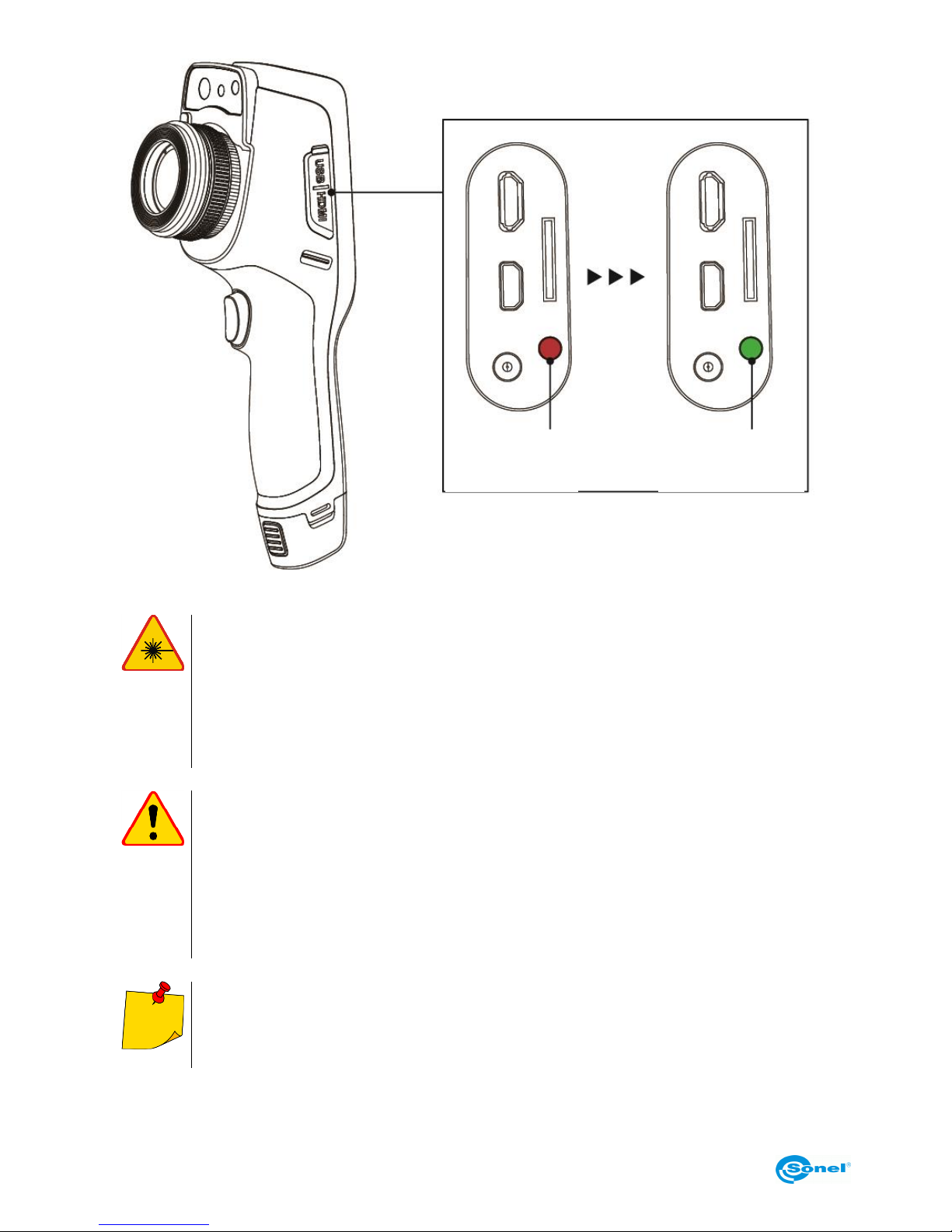
When the battery is charging, the charging indicator light on the side of the camera lights
up red.
When the battery is fully charged, the charging indicator light changes from red to green,
indicating that no further charging is required.
Page 8
KT-195 ● KT-385 ● KT-200 ● KT-400 – USER MANUAL
8
Charging indicator lights
WARNING
Laser locator installed in the camera may be dangerous to eyes, in case of di-
rect contact!
DO NOT DIRECTED THE LASER BEAM TOWARDS OTHER PERSONS OR
ANIMALS!
Please note that the laser beam may reflect off shiny surfaces.
NOTE!
KT series thermal imagers have no parts that could be repaired or modified by its
user. Never attempt to dismantle or modify the device. Opening up the unit invali-
dates the warranty.
Use only standard and additional accessories, listed in "Equipment" section. Using
other accessories does not ensure proper operation of the camera and may cause
its damage.
Due to the continuous development of the device, the design of the display and its
certain features may be slightly different than presented in this manual..
For proper battery performance, charge unused batteries every 3 months. If you do
not use the unit for a long time, remove the batteries and store them separately.
Not fully
charged
Fully charged
Page 9

KT-195 ● KT-385 ● KT-200 ● KT-400 – USER MANUAL
9
2 Description of the camera
Thank you for purchasing our thermal imager.
KT series imagers are modern, high-quality, easy and safe to use measuring devices. They allow to
capture high-quality, fully radiometric thermal images. This product combines high-quality measurement parameters with an innovative and intuitive interface, based on a new operating system, to create an intelligent solution in the field of thermal imaging.
The camera operation, with a large, touch screen is very easy. In addition to standard modes like IR
(infrared), visual and PIP (picture in picture), the camera has a new mode for mixing images, overlapping and blending outlines of the visual image on the infrared image. User can take and store static images or record and save video clips. The available range of software tools allows an image analysis on the go, also in the live mode. Each infrared image can have a text note, voice annotation
and/or sketch attached to it. On site reports are possible with the embedded PDF report editor. The
camera provides a number of ways to connect to external devices, both wired (USB, HDMI) and wirelessly (Wi-Fi).
Please acquaint yourself with this manual to improve your daily work with the device, and to avoid
measuring errors and prevent possible problems related to operation of the imager.
The camera operation and available options may vary, depending on the camera
model. This manual describes the operation based on the highest specs model
available.
Page 10
KT-195 ● KT-385 ● KT-200 ● KT-400 – USER MANUAL
10
3 Function buttons and menu
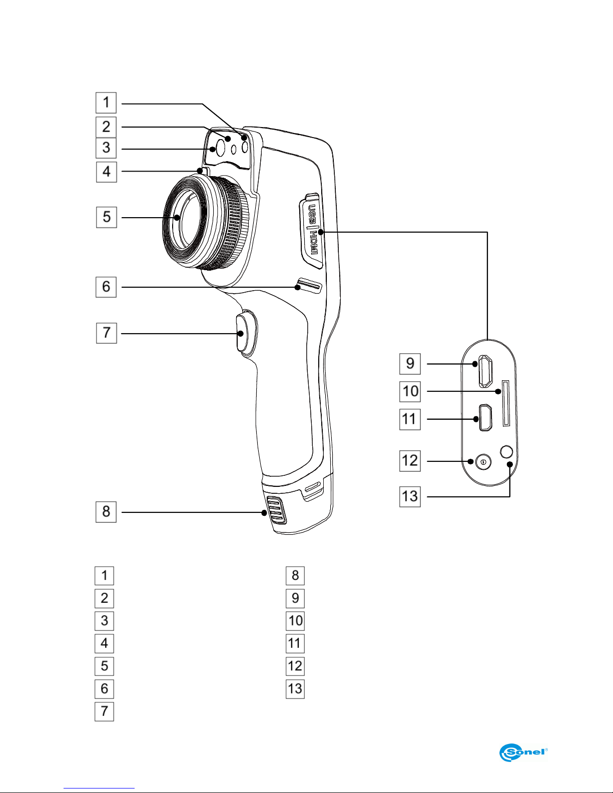
3.1 Camera body description
Flashlight
Battery release button
Laser pointer
micro USB connector
Visual image camera
micro SD card slot
Lens release button
micro HDMI connector
Lens
Power supply connector
Wrist strap holder
Charging indicator
Trigger button
Page 11
KT-195 ● KT-385 ● KT-200 ● KT-400 – USER MANUAL
11
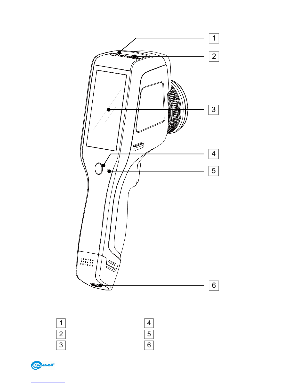
Power On/Off button
Return button
Speaker
Microphone
LCD display
Battery lock
Page 12
KT-195 ● KT-385 ● KT-200 ● KT-400 – USER MANUAL
12
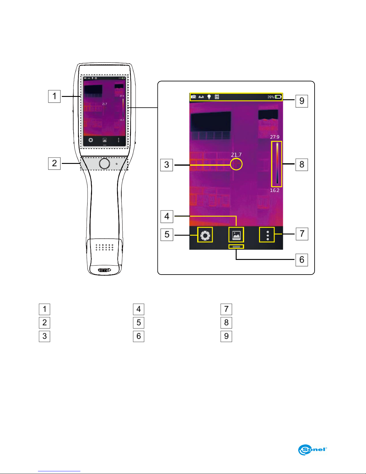
3.2 Overview of the camera’s functional areas
A. Functional areas
Display area
Gallery
Real-time editing mode
Control area
System settings
Palette
Central point cursor
Shortcut menu button
Status identification area
Page 13
KT-195 ● KT-385 ● KT-200 ● KT-400 – USER MANUAL
13
B. Gallery
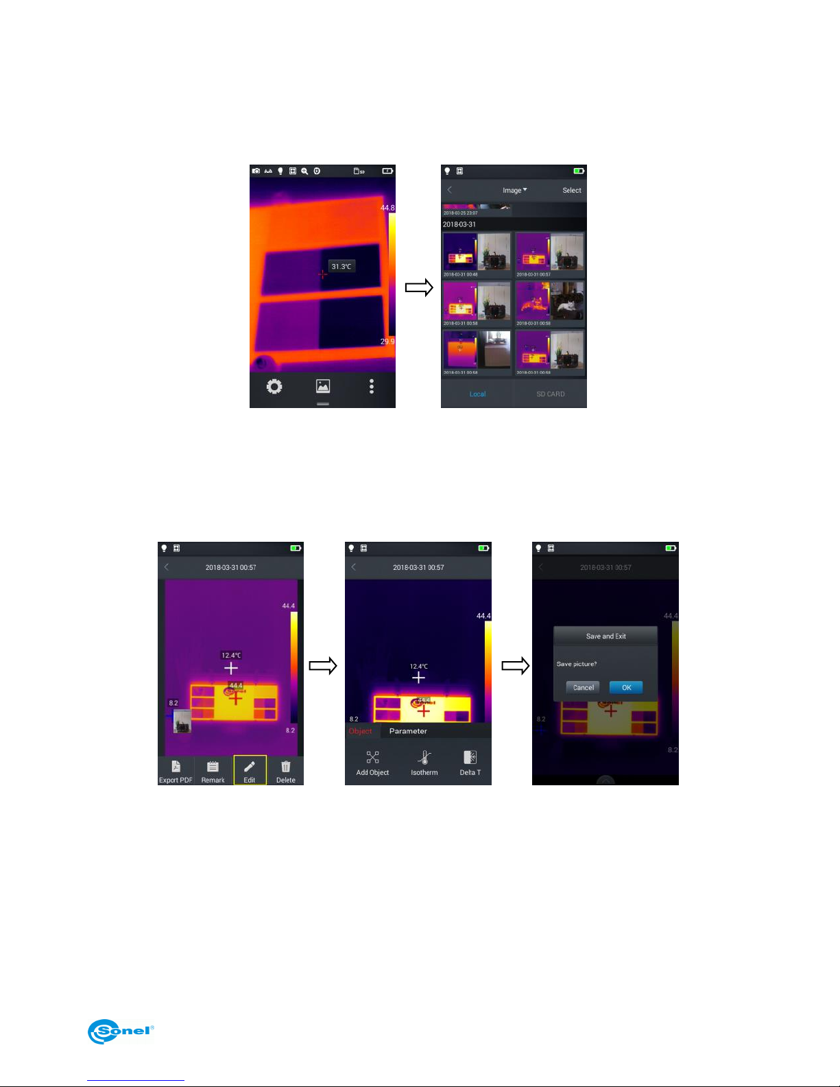
1. Click the gallery button in the main menu. This will display the image overview mode. Click the
image you want to view and analyze, and the image editing screen will appear.
2. Tap the Edit button at the bottom to enter the analysis object editing areas. When the image is
modified, the system will prompt a dialog box asking to save the changes: Save Picture? press
OK to save modifications, or Cancel to keep the image unchanged.
Page 14

KT-195 ● KT-385 ● KT-200 ● KT-400 – USER MANUAL
14
C. Shortcut menu
The interface displays shortcuts for some of the operations that can be performed in real-time, mainly
including: changing the picture mode, flashlight on/off button, laser on/off button, wireless access
point switch, etc.
How to enter the shortcut menu:
1. In real-time image mode, press the shortcut icon [—] at the bottom of the screen.
2. The shortcut menu includes the following content:
IR Mode (image): switches between modes: infrared, visible, fusion and PIP.
Camera Mode: camera operation mode: switching between image taking mode and video record-
ing mode.
Light: turns the flashlight on/off.
Laser: turns the laser pointer on/off.
AP: turns the wireless access point on/off.
Digital zoom: sets the digital magnification from x1 to x4.
USB Realtime Video: enables/disables the USB video connection in real time mode.
Page 15
KT-195 ● KT-385 ● KT-200 ● KT-400 – USER MANUAL
15
3.3 Manual Calibration
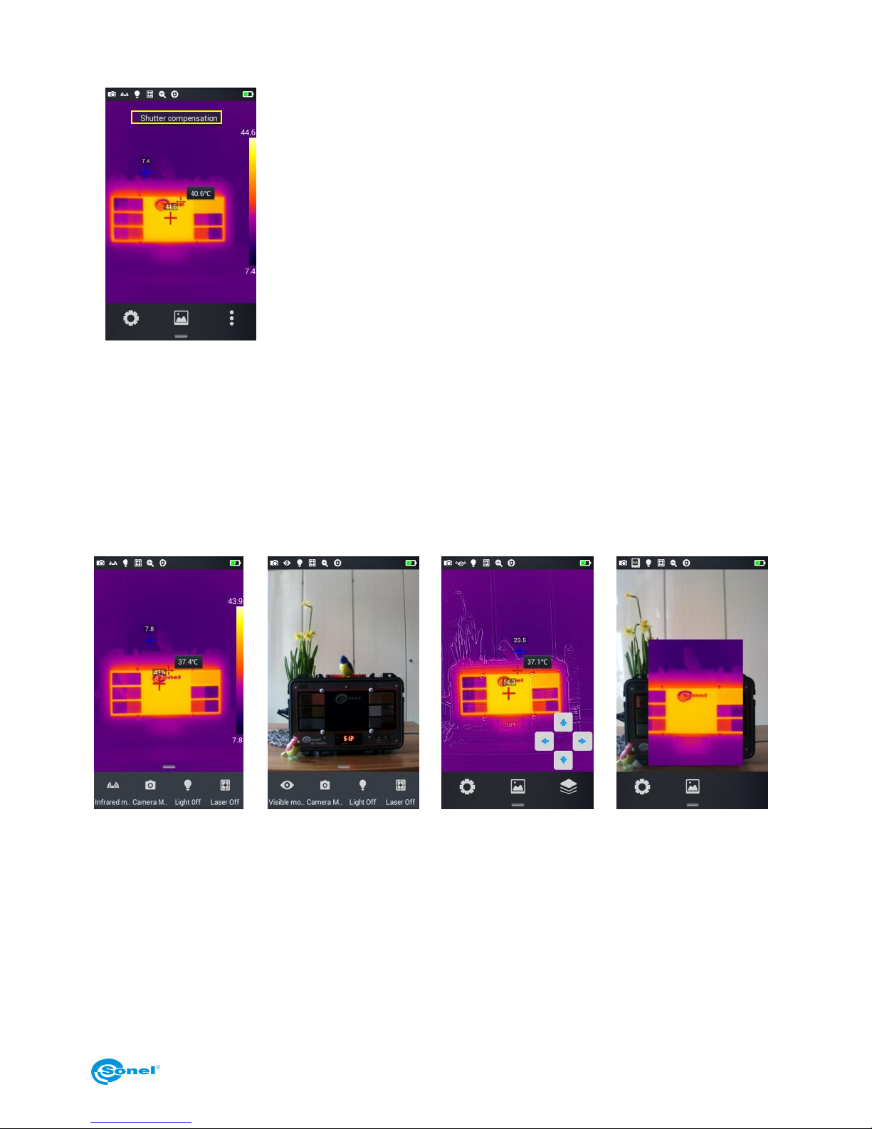
During operation the camera performs auto calibration procedure every
once in a while (signaled by the sound of a camera shutter). During the
calibration, for about 1 second, the device does not respond to us-
er’s activity, during this time the sound of a shutter clicking twice is
heard. The calibration can be triggered manually at any time. To do
that tap the screen twice at any place while the camera is in real time
mode. The camera will carry out the calibration procedure followed by
a message displayed on the screen.
4 Observation
4.1 Image mode switch
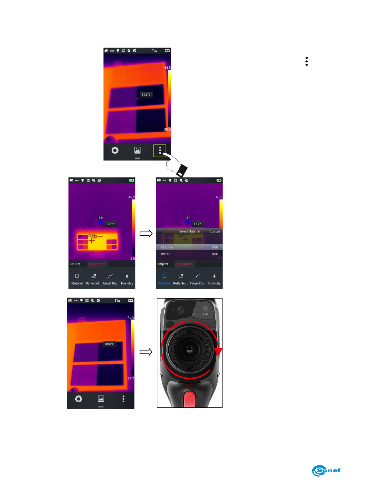
Enter the real-time image mode and tap the IR mode button on the shortcut menu multiple times to
perform multiple mode switching operations for the current image.
The screen can be switched between the following four modes:
A. Infrared
B. Visible
C. Fusion
D. PIP
Page 16
KT-195 ● KT-385 ● KT-200 ● KT-400 – USER MANUAL
16
4.2 Temperature measurement
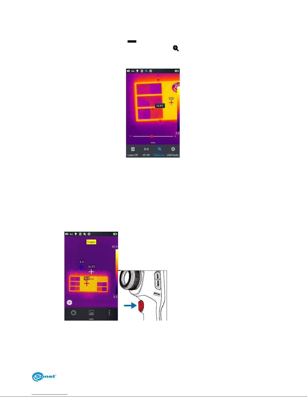
1. In real-time image mode tap the
shortcut menu button [ ]in the
lower right corner of the screen.
2.
Tap the material settings button
in the Parameter menu, go to
Material and select the emissivity of the measured object by:
swiping the list of materials up
and down, or
by selecting Custom option
and set the emissivity value
with the slider.
Then tap Back button twice or
press the IR image on the
screen to save the changes and
return to the real time mode.
3.
Align the central point cursor
with the measured object for
temperature measurement. Rotate the outer lens clockwise or
counter clockwise to adjust the
focus point.
Page 17
KT-195 ● KT-385 ● KT-200 ● KT-400 – USER MANUAL
17
4.3 Digital Zoom
In the real time image mode, press the [ ] button at the bottom to open the shortcut menu and then
slide the shortcut bar to the left to the Digital Zoom option [ ], to allow up to 4 times real time image
magnification, by sliding the status bar left to right.
5 Images
5.1 Capturing images
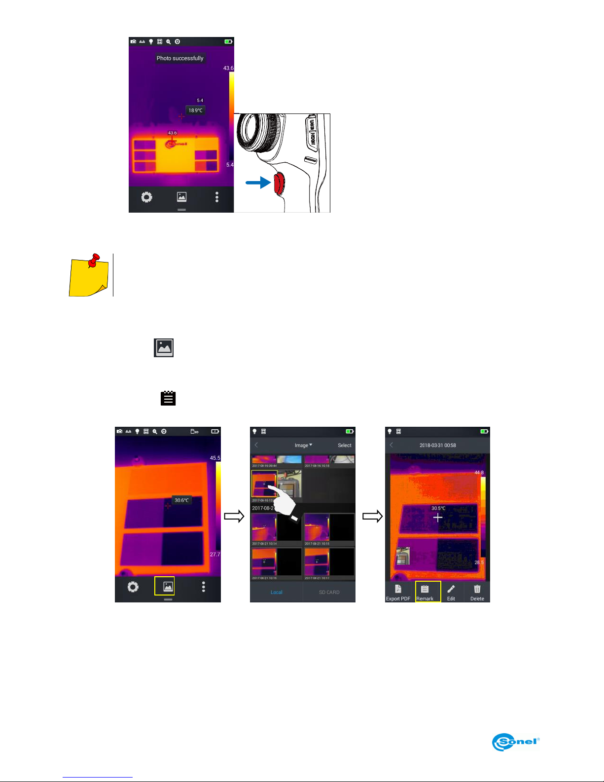
Set the trigger button function in the system settings.
For freeze/photo mode:
1.
Press trigger button to freeze an
image.
Page 18
KT-195 ● KT-385 ● KT-200 ● KT-400 – USER MANUAL
18
2.
With the image frozen, press the
trigger button again to save the
image.
This function works only in the infrared mode.
5.2 Adding notes
1. Tap the Gallery icon in the middle of the bottom menu to enter the file browsing directory.
2. Select the image to which a note is to be added, by tapping it on the touch screen. The image preview will be displayed.
3. Tap the Remark [ ] icon, to enter the notes adding menu.
Page 19
KT-195 ● KT-385 ● KT-200 ● KT-400 – USER MANUAL
19
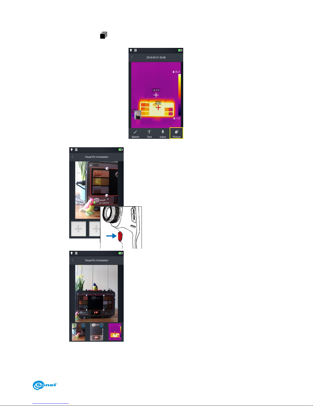
5.2.1 Adding picture notes
1. Tap the Picture note [ ] icon in the toolbar below to enter the main interface for the picture
notes.
2.
Press the trigger button to take up to two photos in a
visible light mode as shown in the figure below.
3.
If the picture is not taken correctly, it can be deleted
by pressing the delete button (X) in the upper right
corner of the photo and then a new one can be taken.
Page 20
KT-195 ● KT-385 ● KT-200 ● KT-400 – USER MANUAL
20
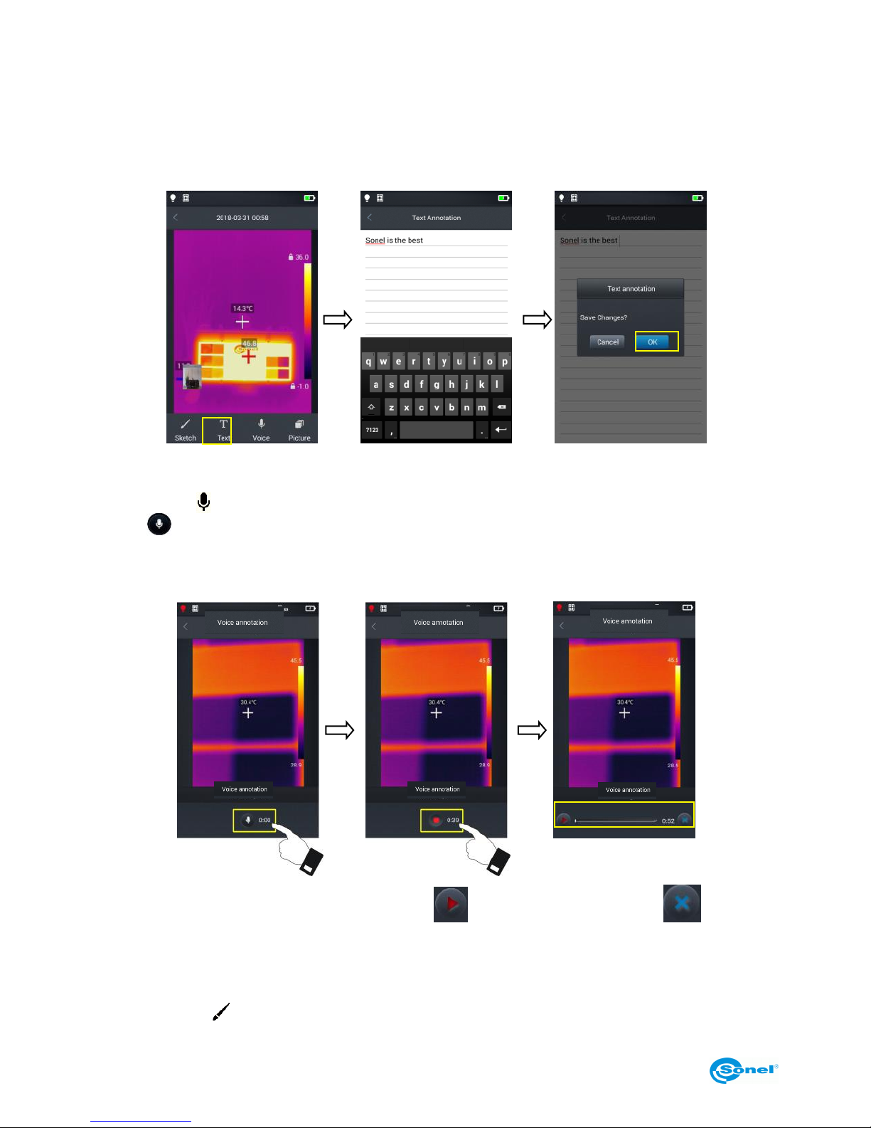
5.2.2 Adding text notes
1. Tap Text [T] button to add a text note;
2. Access the note input field and enter the text note content;
3. Press the Return hardware button or the onscreen [<] symbol twice;
4. Press Ok, to save the text note or Cancel to exit without saving.
5.3 Adding voice notes
1. Tap Voice [ ] button to add a voice note;
2. Tap [ ] to start recording;
3. Tap Stop to stop recording and save the recorded file. The recording time for a single voice note is
limited to 60 s by default, as shown in the figure below.
4. Play the recorded voice note by tapping PLAY button or delete by pressing .
5. Press the Return hardware button or the onscreen [<] symbol.
6. Press Ok, to save the voice note or Cancel to exit without saving.
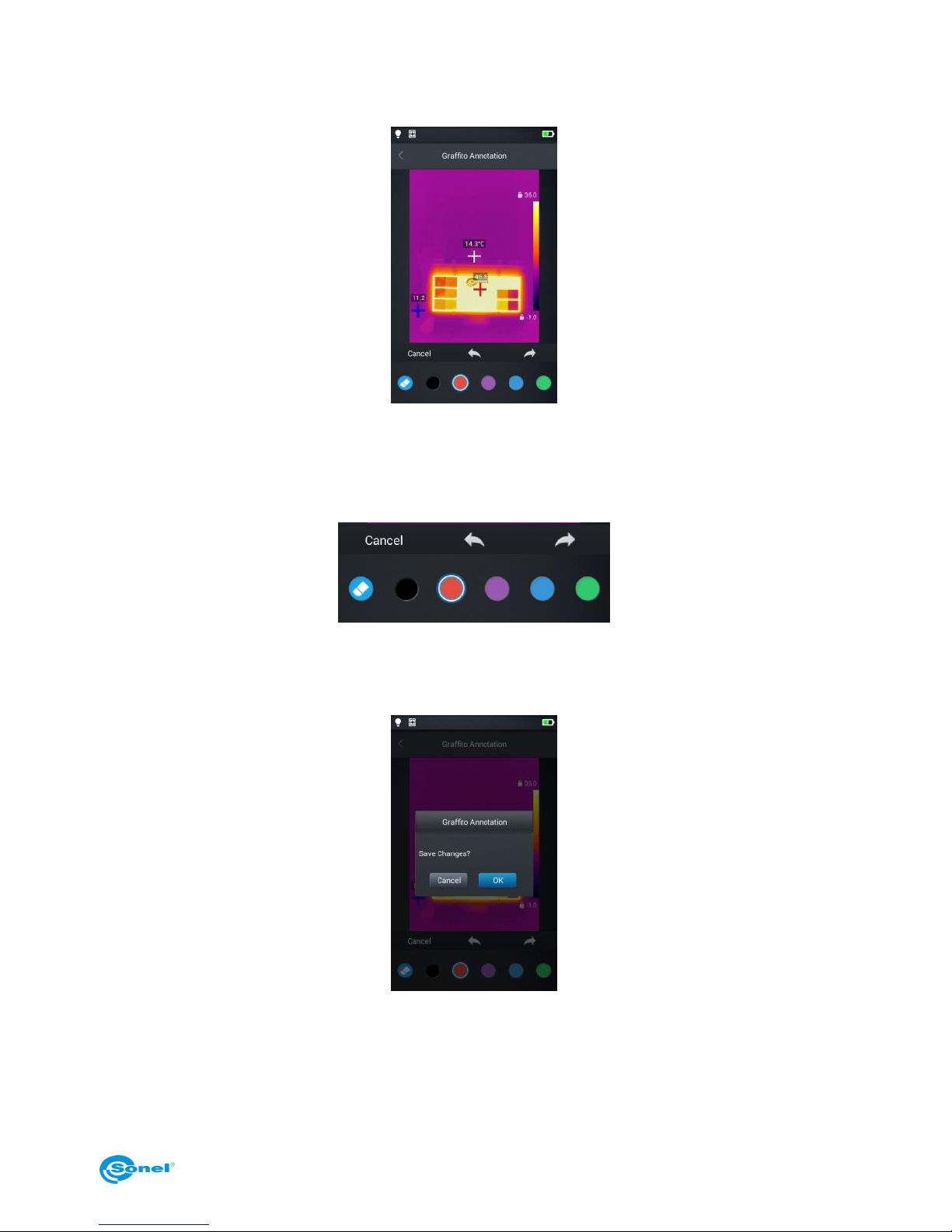
5.4 Adding sketch note
1. Tap Sketch [ ] button to add a sketch note;
Page 21
KT-195 ● KT-385 ● KT-200 ● KT-400 – USER MANUAL
21
2. The buttons at the bottom are eraser (to delete previously drawn sketch) and color (brush) selection. User can select any button and draw a sketch in the image field.
3. Additional functional buttons are (from left to right): Cancel - wipes all the drawings off the
screen, Back – removes the last sketch bit, Restore – brings the most recently deleted element
back on screen.
4. Once the sketch note is complete, the Return hardware button or the onscreen [<] symbol;
6. Press Ok to save the sketch note or Cancel to exit without saving.
Page 22
KT-195 ● KT-385 ● KT-200 ● KT-400 – USER MANUAL
22
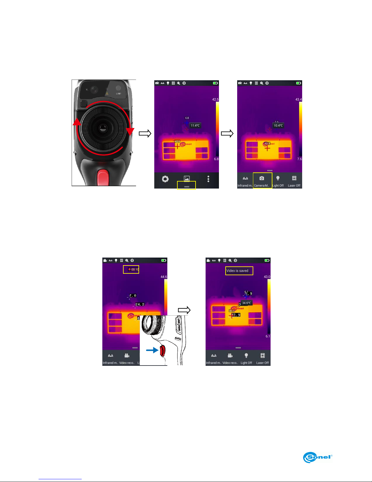
5.5 Video recording
1. Switch to the real time mode and point the camera at the object (it is recommended to adjust the
focus before starting recording a video);
2. Tap the shortcut menu button at the bottom and then the Camera button to enter the video recording mode;
3. Press the trigger button to start recording. Recording time information will be displayed at the top
of the screen.
4. Press the trigger button again to stop recording and the video data will be saved. It can later be
checked and played in the gallery.
Page 23
KT-195 ● KT-385 ● KT-200 ● KT-400 – USER MANUAL
23
5.6 Real-time analysis
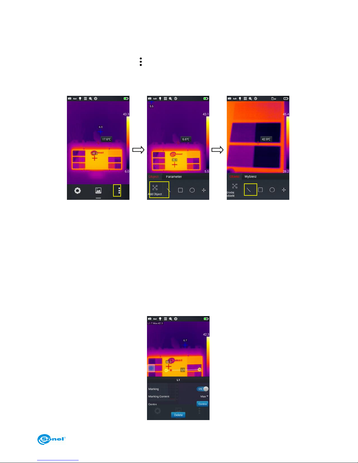
5.6.1 Adding/removing the analysis object
1. Tap the shortcut menu button [ ] on the right in real-time mode and enter the mode of adding
analysis objects, as shown in the figure.
2. Temperature measurement of various analysis objects such as lines, rectangles, circles and
points are available. Additionally, a maximum, minimum and average temperatures, as well as
the central point temperature, can be displayed on screen.
Press and hold any of the analysis objects on the touch screen for a few seconds, to display an object menu with the following functions:
Marking: displays the symbolic name of the object when switched on (ON).
Marking Content: displays the maximum (red star), minimum (blue star) or average (two stars) tem-
peratures of the object. The selected temperature is displayed in the upper left corner of the screen.
Centre: press to reposition the selected analysis object to the centre of the screen.
Delete: deletes selected analysis object.
Page 24
KT-195 ● KT-385 ● KT-200 ● KT-400 – USER MANUAL
24
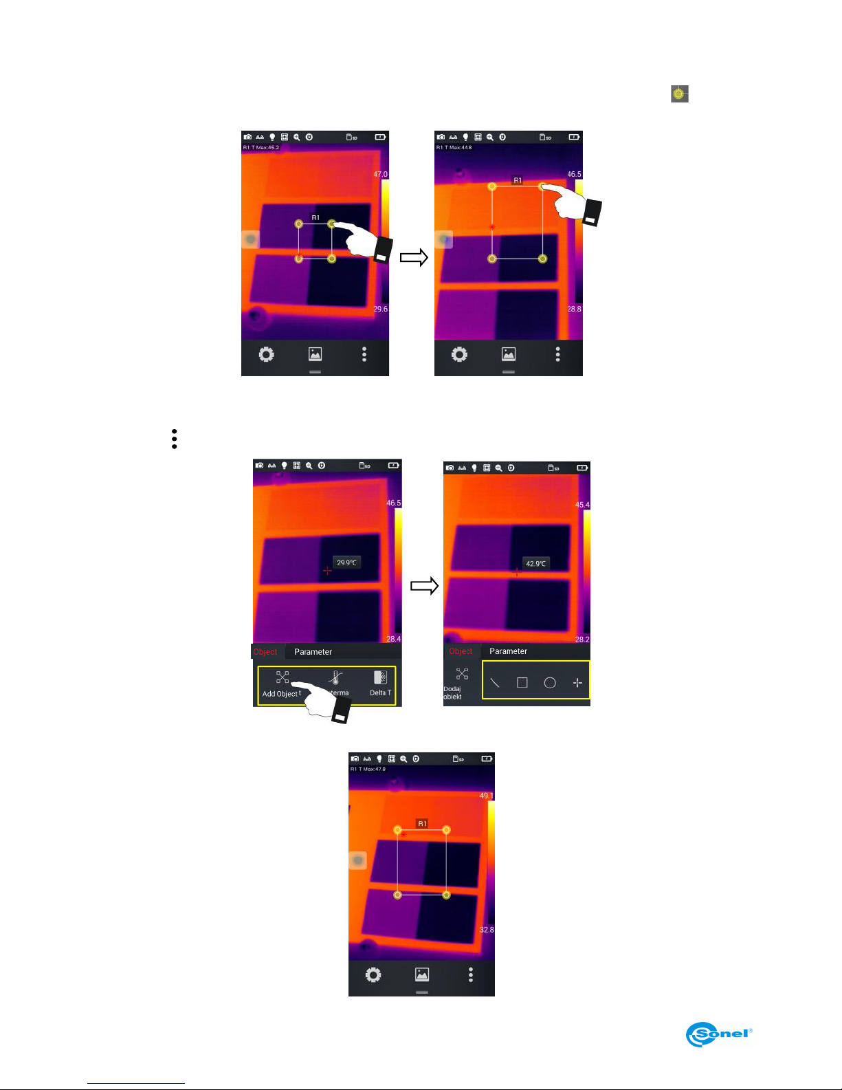
5.6.2 Resizing the analysis objects
1. Select an analysis object - its nodes will be selected and displayed as yellow markers [ ];
2. Move any node – the analysis object area will be changed.
5.6.3 Analysis function of a moving object
1. Tap the [ ] button to display a submenu for adding the analysis object.
2. Select the desired analysis objects, eg. a rectangle
Page 25
KT-195 ● KT-385 ● KT-200 ● KT-400 – USER MANUAL
25
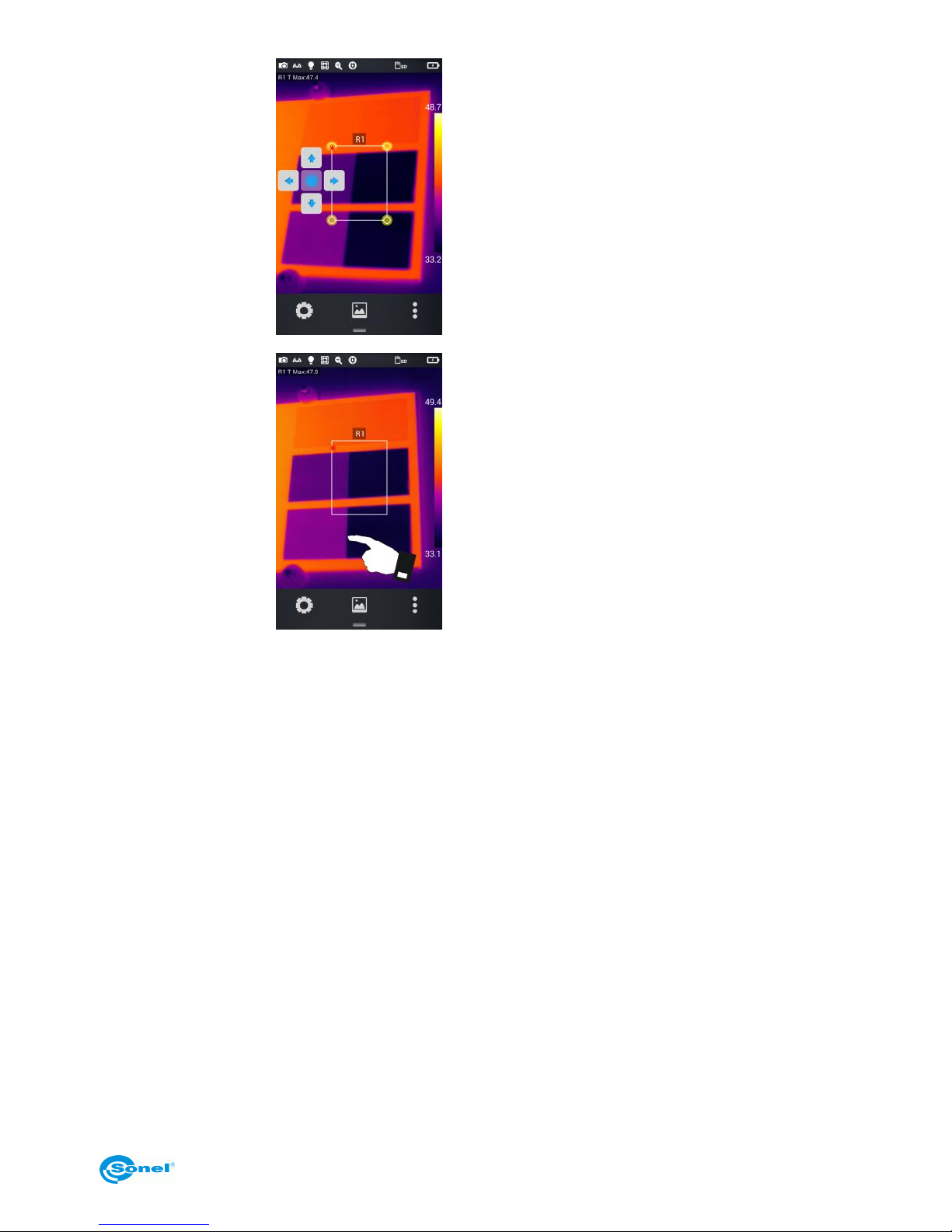
3.
Click the virtual round button to
view the virtual cursors. The analysis objects can be moved
up/down and right/left with them.
4.
Tap any place on the screen outside the analysis objects to hide
the virtual cursors (tap the analysis
objects again to bring back the
cursors).
5.
Select one of the many analysis objects, and the selected object will be able to be moved using
virtual cursors.
Page 26
KT-195 ● KT-385 ● KT-200 ● KT-400 – USER MANUAL
26
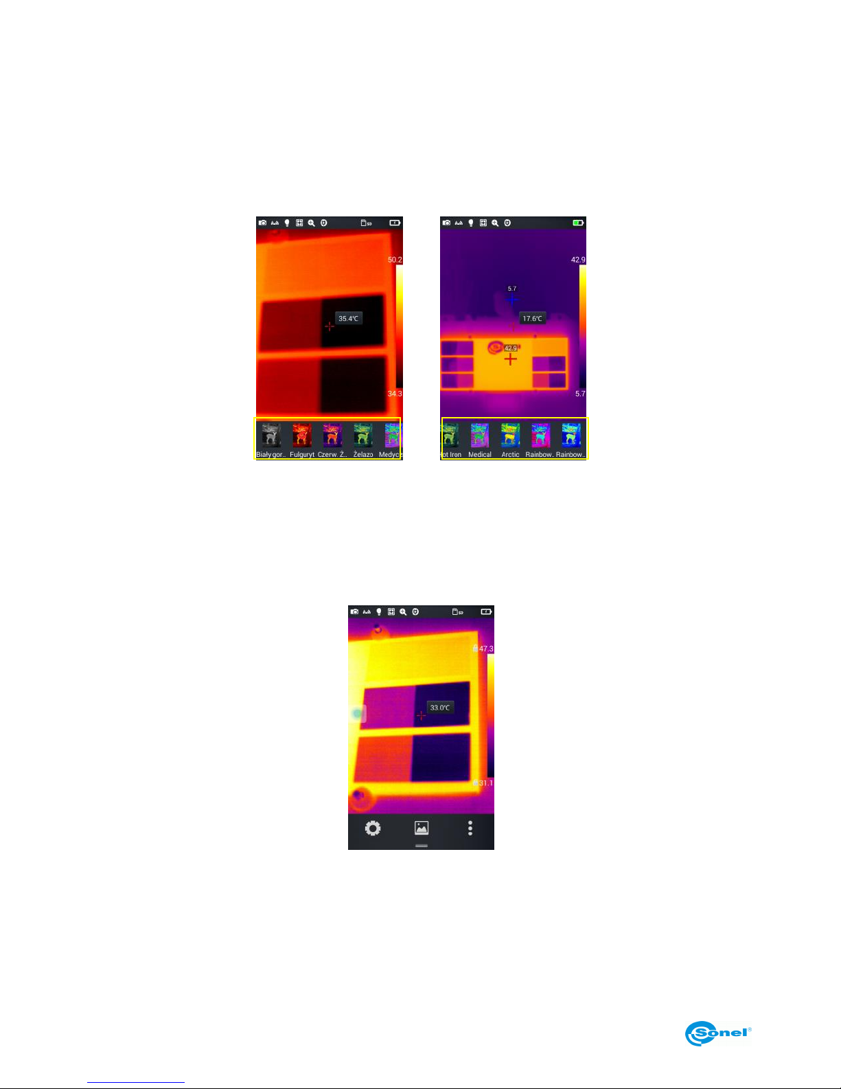
5.6.4 Selecting a color palette
1. Go to the main menu, tap the palette area on the right side of the screen - the palette types will
appear, including White Hot, Fulgurite, Iron Red, Hot Iron, Medical, Arctic, Rainbow 1, Rain-
bow 2.
2. The user can switch between palette types as desired, as shown in the figure.
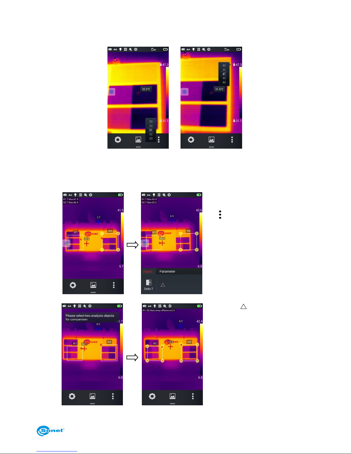
5.6.5 Manual brightness/contrast control
1. In the real-time image mode, press the maximum temperature value or the minimum temperature
value of the colour bar on the right side of the screen.
2. A maximum or a minimum value of the colour bar temperature in the real-time image mode will
be locked.
Page 27
KT-195 ● KT-385 ● KT-200 ● KT-400 – USER MANUAL
27
3. Press the maximum or the minimum temperature - the imager will display the corresponding val-
ue menu;
4. After selecting the appropriate high or low temperature value, press any part of the IR image to
close the selection window and the value will be saved.
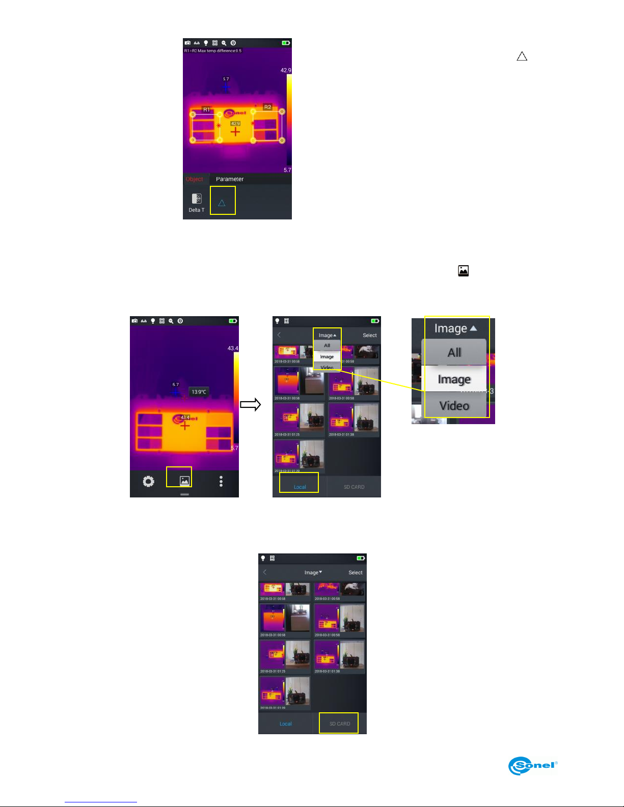
5.6.6 Temperature difference analysis
1.
Select at least 2 analysis objects,
press the shortcut menu button
[ ] and then the
Delta T temperature difference
button;
2.
Tap the [ ] button, to activate the
temperature difference mode and
select two objects for analysis
Page 28
KT-195 ● KT-385 ● KT-200 ● KT-400 – USER MANUAL
28
3.
Exiting the temperature difference analysis mode
To exit the temperature difference
analysis mode, press the [ ] but-
ton again.
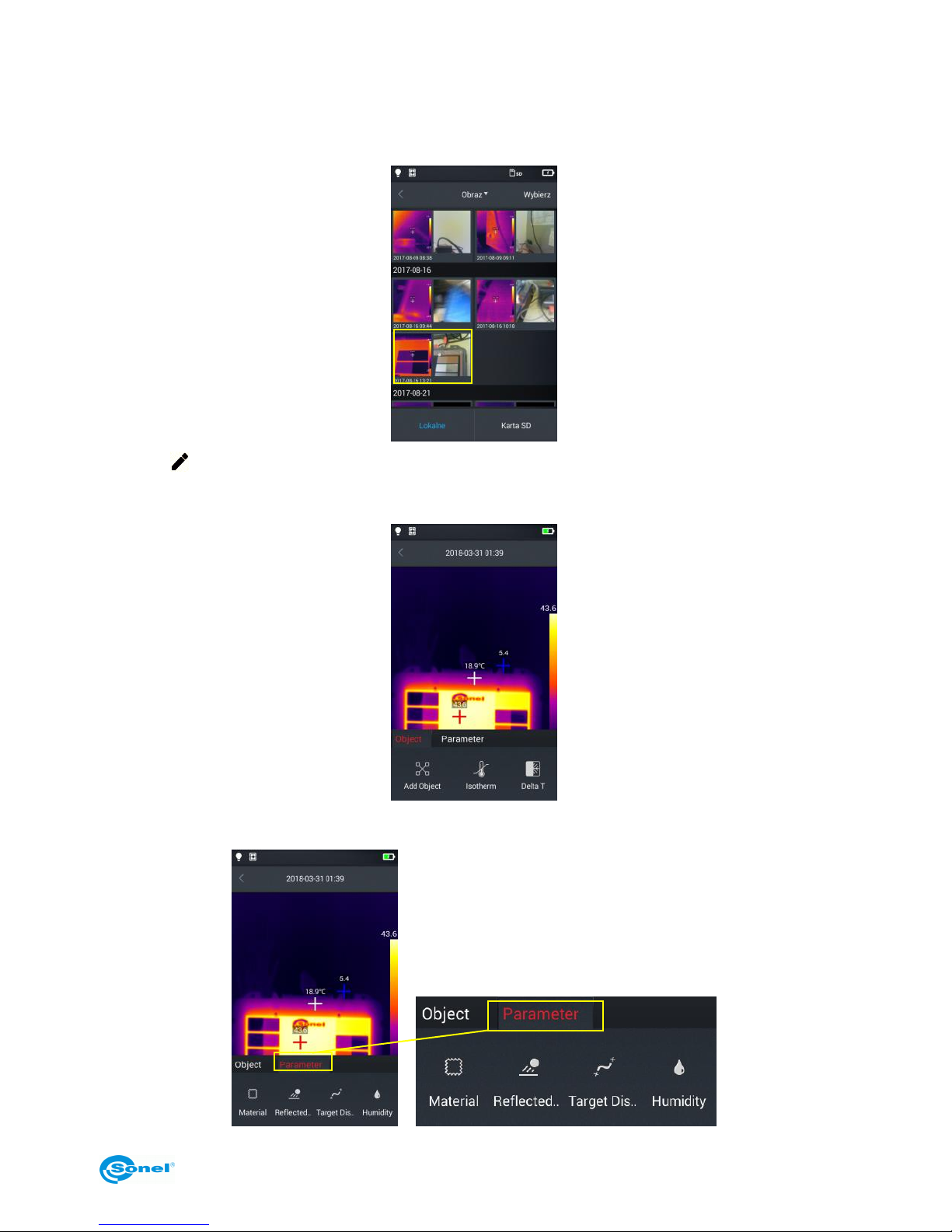
5.7 File browsing
1. Local pictures and videos: in real-time image mode tap gallery button [ ], to enter the file
browsing main menu, select Image → All – and the system will automatically display all local
files.
2. Files and videos on a microSD card: In the real-time image mode, tap the gallery button to enter the file browsing main menu, then press SD CARD - the system will display all the files on the
microSD card.
Page 29
KT-195 ● KT-385 ● KT-200 ● KT-400 – USER MANUAL
29
5.8 Image analysis
5.8.1 Image editing
1. In file browsing mode, press any photo to enter the image editing mode;
2. Tap [ ] button - the system will enter the edit mode. In this mode, following elements can be
added or modified: analysis object, isotherm and temperature difference (Delta T) between two
points for the selected picture.
3. Tap Parameter button, to modify other parameters.
Page 30
KT-195 ● KT-385 ● KT-200 ● KT-400 – USER MANUAL
30
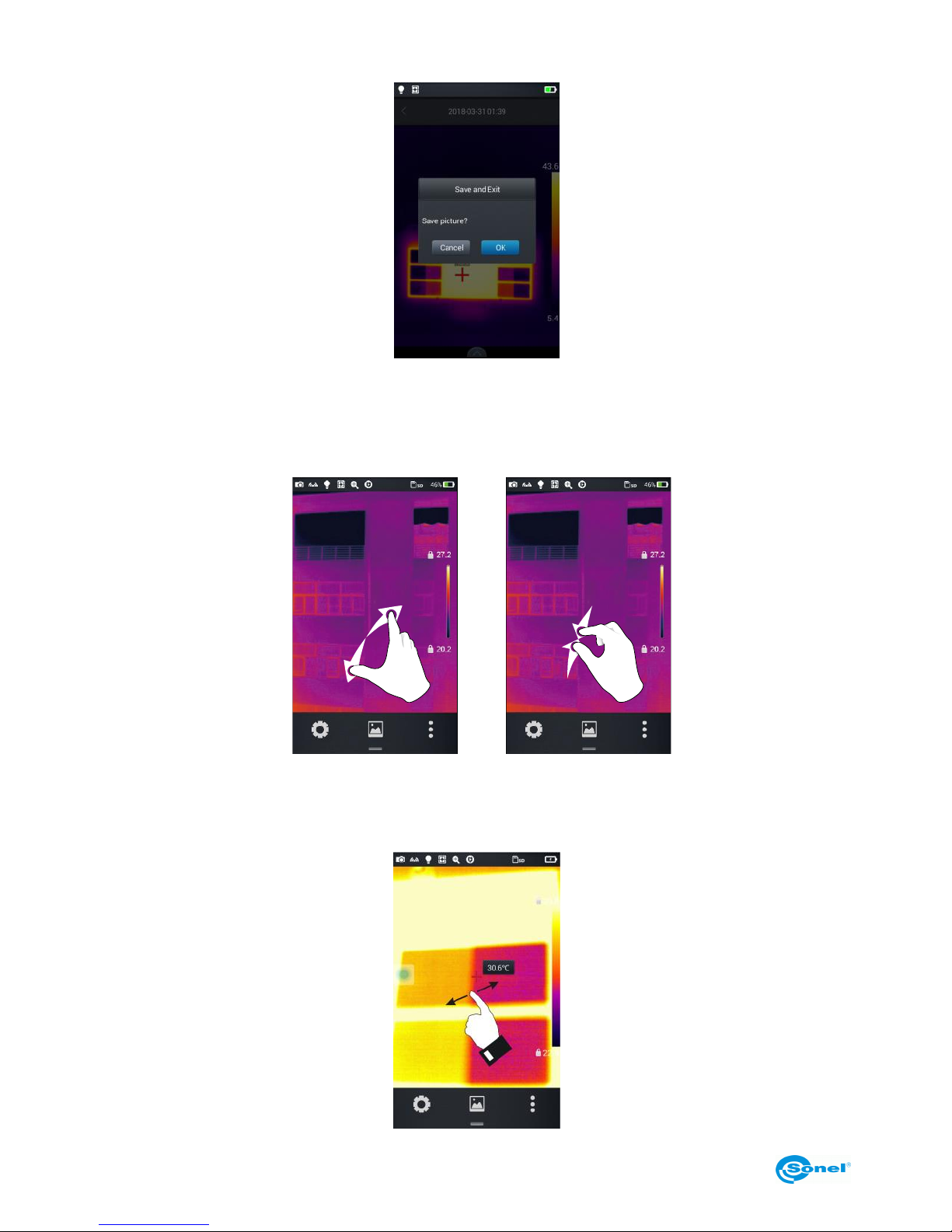
4. Press OK to exit this mode and to save the settings, as shown in the figure below.
5.8.2 Zooming in and out
1. In edit mode, place two fingers on the screen and spread them apart. Doing this the photo can be
enlarged up to 10 times.
2. Place two fingers on the screen and pinch them close to downsize an image.
+
Zooming in Zooming out
3. To slide an enlarged image within the screen, place one finger on the screen and move it in the
desired direction The enlarged image can be moved by swiping a finger across the screen.
Page 31
KT-195 ● KT-385 ● KT-200 ● KT-400 – USER MANUAL
31
5.9 Creating a PDF file
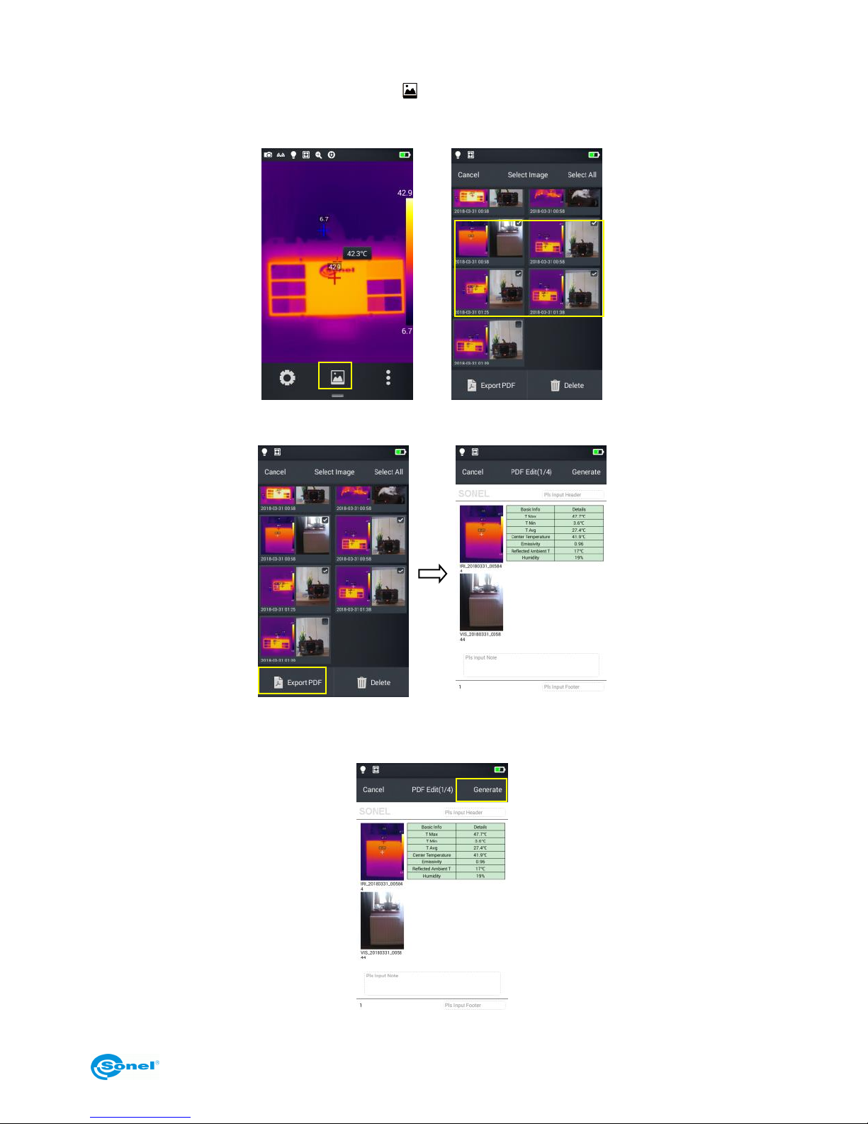
1. In real-time image mode tap gallery button [ ];
2. Tap Select button, and choose up to 5 images as shown in the figure below;
3. Press Export PDF button in the lower left corner to create a PDF file preview.
4. Press the Generate button to create the file.
Page 32
KT-195 ● KT-385 ● KT-200 ● KT-400 – USER MANUAL
32
5.10 PDF file printing
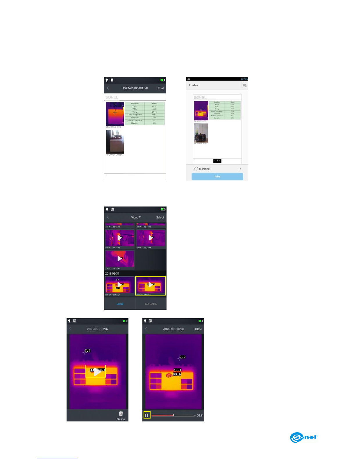
1. In Connecting settings connect to a wireless Wi-Fi network (wireless printing).
2. Select a picture in the gallery and generate a PDF (see section 5.9 for detailed information).
3. Press the Print button at the top right side of the PDF preview interface.
4. In Print Ready mode, press Print to print wirelessly.
Printing PDF
Wireless printing preview
5.11 Video playback
1.
In gallery select Image → Local
Video and select a video file to
play;
2.
Play the video:
Follow these steps:
Tap 'Play' button at the center
of the screen to play the video;
Tap 'Pause' button at the bot-
tom of the screen to suspend
video playback
Page 33
KT-195 ● KT-385 ● KT-200 ● KT-400 – USER MANUAL
33
5.12 Isotherm
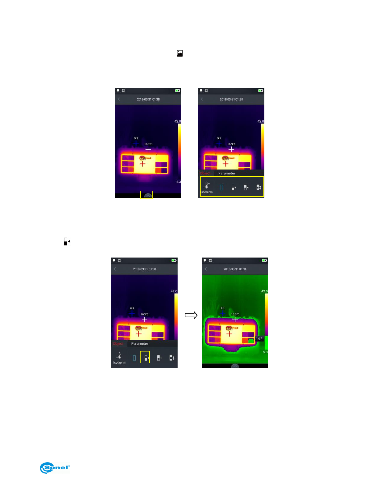
1. In real-time image mode tap gallery button [ ],to enter the file browsing menu;
2. Select and edit an infrared image;
3. Enter the edit menu at the bottom and select Object → Isotherm.
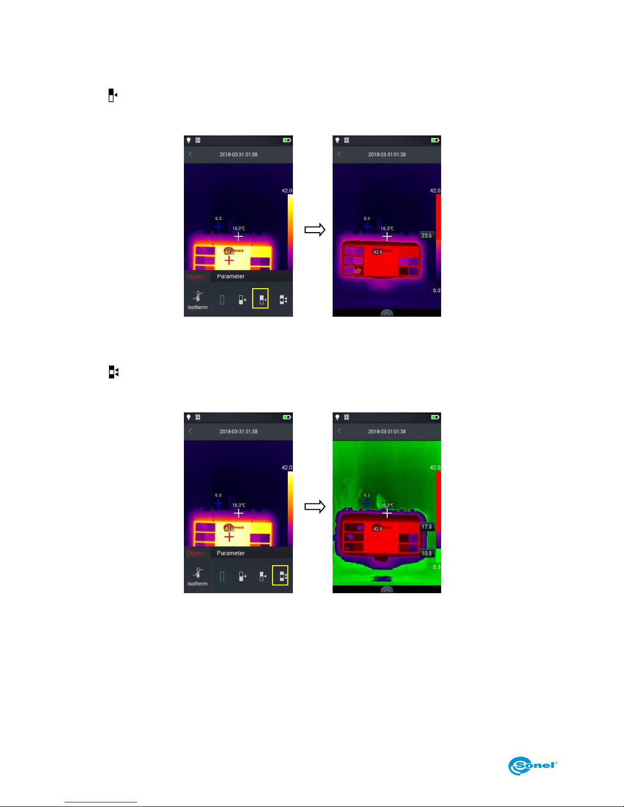
5.12.1 High isotherm
1. Enter the edit mode and select Object → Isotherm.
2. Tap [ ] icon on the isotherm bar – the camera will display a target view for the high isotherm picture mode.
Page 34
KT-195 ● KT-385 ● KT-200 ● KT-400 – USER MANUAL
34
5.12.2 Low isotherm
1. Enter the edit mode and select Object → Isotherm.
2. Tap [ ] icon on the isotherm bar – the camera will display a target view for the low isotherm pic-
ture mode.
5.12.3 Out of range isotherm
1. Enter the edit mode and select Object → Isotherm.
2. Tap [ ]icon on the isotherm bar – the camera will display a target view for the out of range iso-
therm picture mode.
Page 35
KT-195 ● KT-385 ● KT-200 ● KT-400 – USER MANUAL
35
5.13 Adjusting temperature range and span
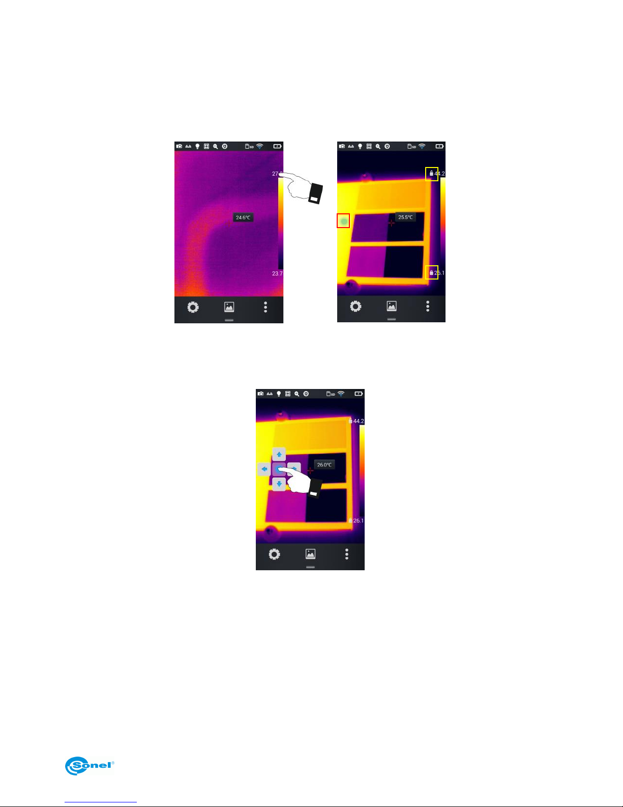
1. Enter the real-time image mode and press the maximum or minimum temperature value on the
color bar on the right side of the screen (see Figure 1 below). The lock symbol will appear next to the
temperature value and the round virtual button will be displayed on the screen (see Figure 2 below).
The mode for a manual contrast adjustment will be initiated.
Figure 1
Figure 2
2. Tap the virtual round button to view the virtual cursors on screen (see Figure 3 below).
Figure 3
5.13.1 Adjusting temperature range
Temperature range adjustment is done by pressing the virtual buttons up/down.
Press the up button to increase the Tmax and Tmin values. Press the down button to decrease the
Tmax and Tmin values. This adjustment will apply a corresponding contrasting color that will be reflected in the real-time image mode.
Page 36
KT-195 ● KT-385 ● KT-200 ● KT-400 – USER MANUAL
36
5.13.2 Adjusting temperature scale span
Adjusting the temperature scale span by pressing the 'left' virtual button.
Press the left button to decrease the Tmax value and increase the Tmin value. This adjustment will
apply a corresponding contrasting color that will be reflected in the real-time image mode.
Adjusting the temperature scale span by pressing the 'right' virtual button.
Press the right button to increase the Tmax value and decrease the Tmin value. This adjustment will
apply a corresponding contrasting color that will be reflected in the real-time image mode.
Double tap any part of the image on the screen to display an automatic contrast adjustment mode.
5.14 Edit menu
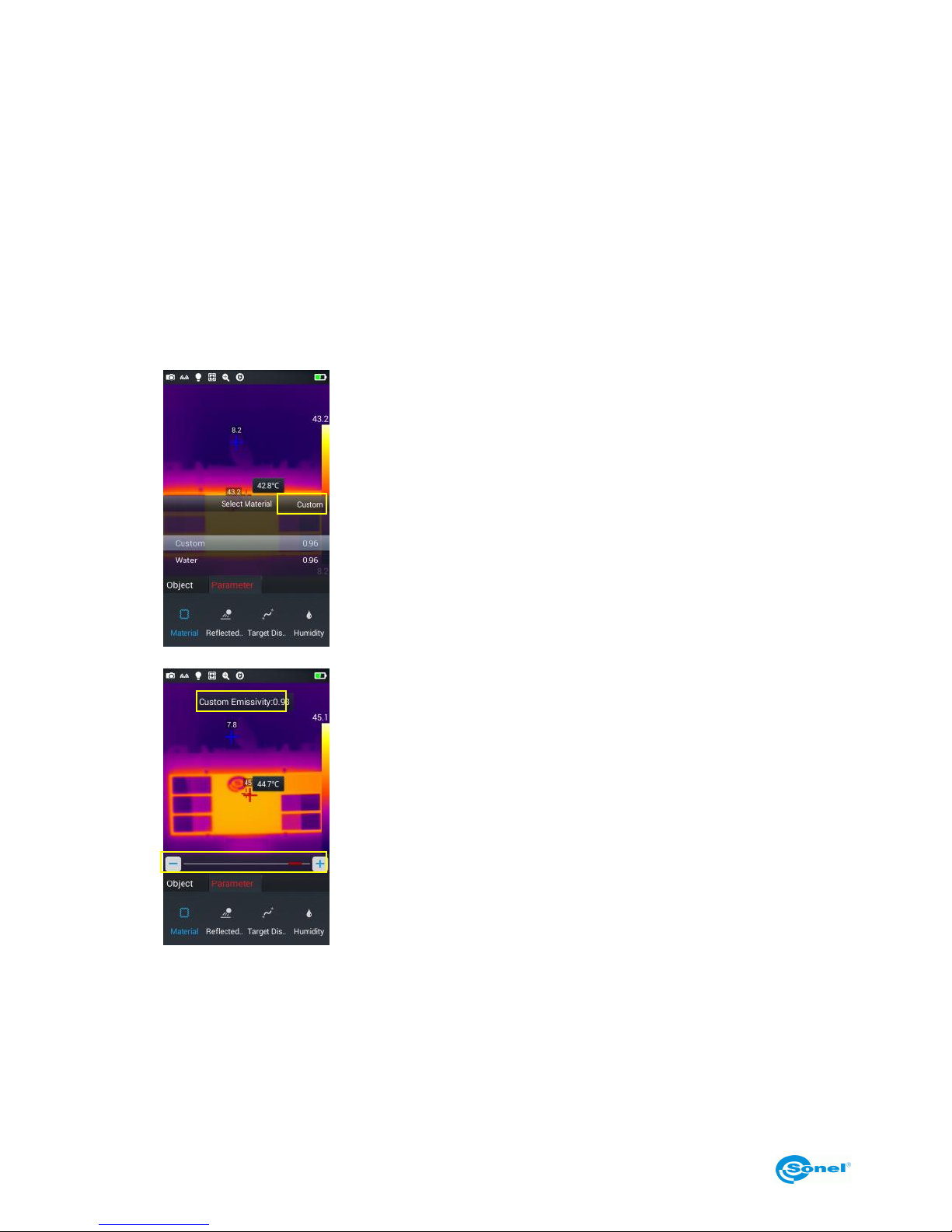
5.14.1 Emissivity
1.
go to Select Parameter → Material in the edit menu. There are
many materials available to select from. To set user defined emissivity, press Custom button.
2.
Modify the parameters as required by sliding the numerical value
from 0.01 to 1.00, as shown in the figure below:
Page 37
KT-195 ● KT-385 ● KT-200 ● KT-400 – USER MANUAL
37
5.14.2 Reflected temperature
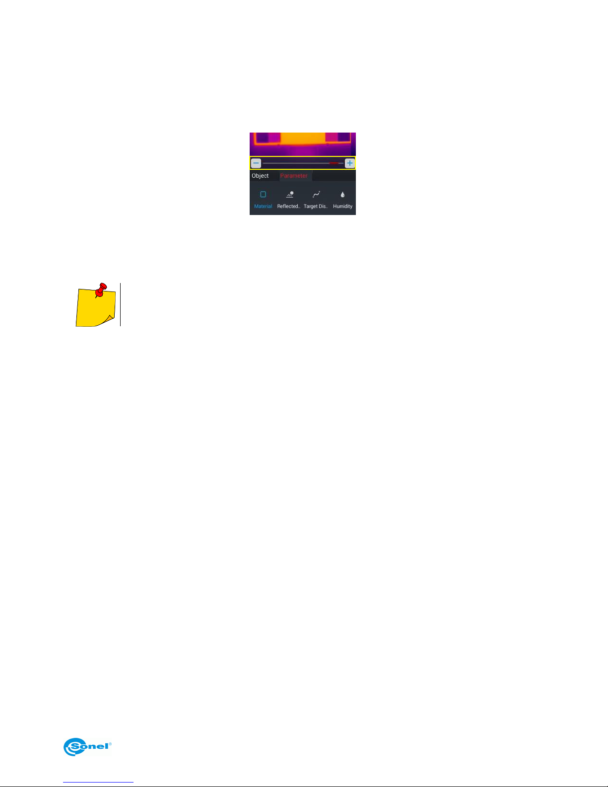
Reflected temperature, also known as ambient temperature. Customizable by slider in the range of: 20°C to 150°C, 150°C to 650°C or 650°C to 1500°C (depending on the camera model and lens type
used).
5.14.3 Target distance
A distance of the camera from the tested object. Customizable in the range: 1 m to 50 m.
To customize the reflected temperature set the Auto option to OFF.
5.14.4 Humidity
Relative humidity at the measurement site: customizable from 0% to 100%.
Page 38
KT-195 ● KT-385 ● KT-200 ● KT-400 – USER MANUAL
38
6 System settings
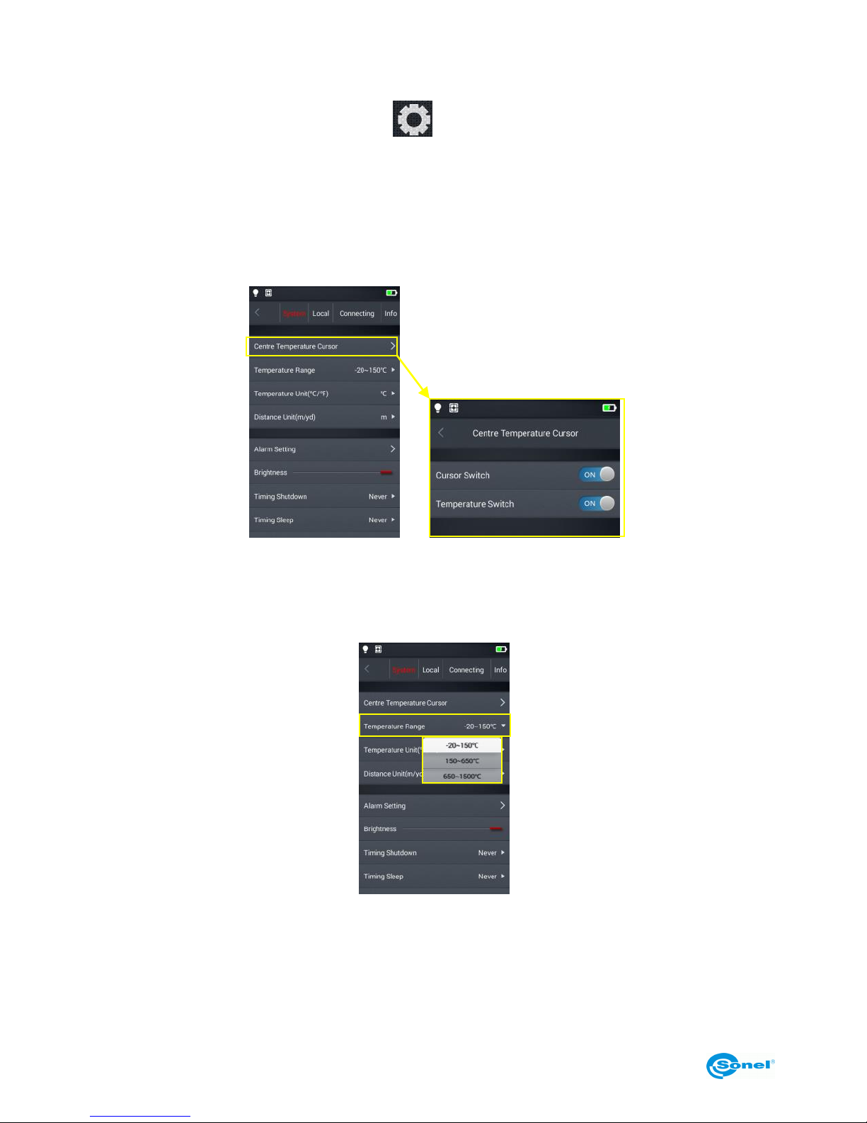
In the real-time mode tap the settings button at the bottom of the screen to enter the global settings mode. In this mode the main parameters of the camera can be changed, including temperature
units, distance units, brightness, network connection, date and language.
6.1 Central Temperature Cursor
This option enables/disables the central point temperature cursor on the screen in real-time image
mode and turns on/off the display of the central point temperature value on screen.
6.2 Temperature measurement range
Allows to set the range of the measurable temperature of the measured object.
Page 39
KT-195 ● KT-385 ● KT-200 ● KT-400 – USER MANUAL
39
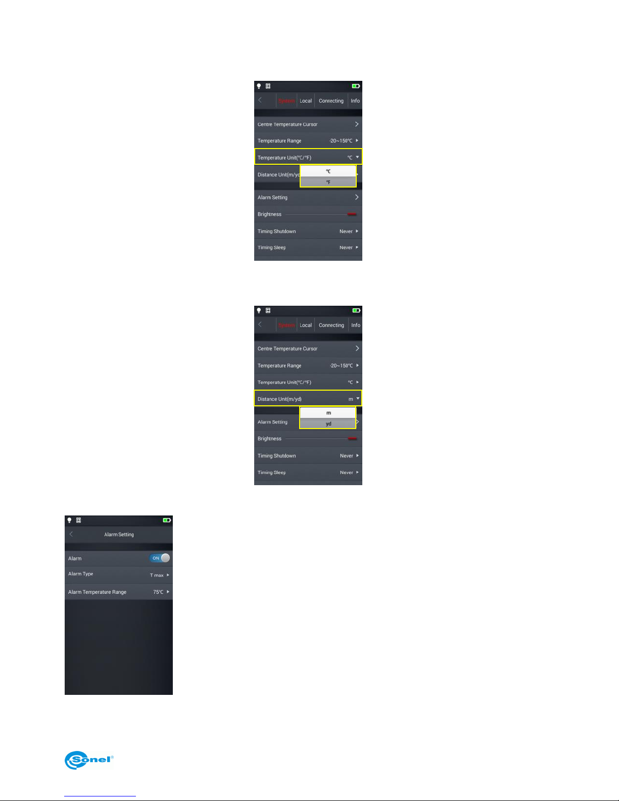
6.3 Temperature unit selection
The temperature can be displayed in °C or °F. Default temperature unit: °C.
6.4 Distance unit selection
The distance unit can be switched between meter and feet. Default distance unit is meter.
6.5 Alarm setting
The alarm can be set to go off when exceeding a defined minimum or
maximum temperature. By default the temperature alarm is off. The alarm
temperature should be set within the selected temperature range, eg. if the
temperature range is set as -20°C to 150°C, then the temperature alarm
value should be defined within this range.
Page 40
KT-195 ● KT-385 ● KT-200 ● KT-400 – USER MANUAL
40
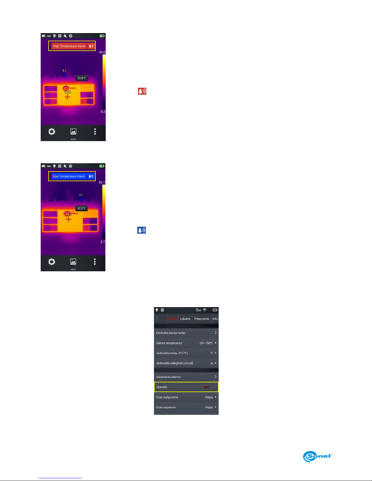
6.5.1 High temperature alarm
1. Activate the temperature alarm, set the alarm type to Tmax and set the
temperature value that triggers the alarm when it's exceeded.
2. When in the real-time temperature measurement mode, once the temperature above the alarm threshold is detected, the device will immediately
trigger an audible alarm and will display a corresponding message on
screen.
3. Tap [ ] icon, to turn off the high temperature sound alarm.
6.5.2 Low temperature alarm
1. Activate the temperature alarm, set the alarm type to Tmin and set the
temperature value that triggers the alarm when the detected temperature
drops below this value.
2. en in the real-time temperature measurement mode, once the temperature below the alarm threshold is detected, the device will immediately
trigger an audible alarm and will display a corresponding message on
screen.
3. Tap [ ] icon, to turn off the high temperature sound alarm.
6.6 Brightness
The brightness of the touch screen can be manually adjusted by the user.
Page 41
KT-195 ● KT-385 ● KT-200 ● KT-400 – USER MANUAL
41
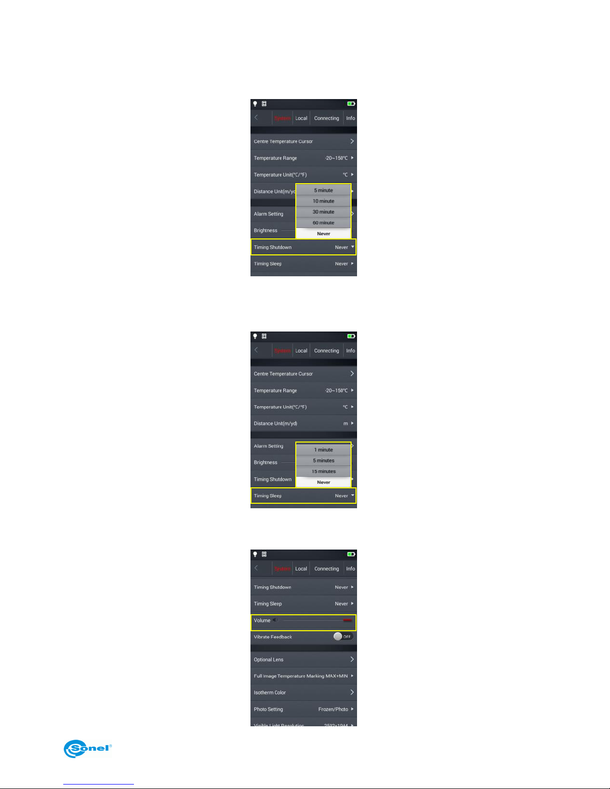
6.7 Auto off time settings (Timing Shutdown)
The camera can automatically shut down when not used for a while. User can define shut down times as 5,
10, 30 or 60 minutes, or choose 'Never Shutdown' option. By default the camera is in 'Never Shutdown'
mode.
6.8 Sleep mode time settings (Timing Sleep)
The camera can be set to go into sleep mode after 1, 5 or 15 minutes of not being used. Sleep mode can
also be deactivated by choosing 'Never Sleep' option. By default the camera is in 'Never Sleep' mode.
6.9 Volume
Adjust the volume of the camera or mute it.
Page 42
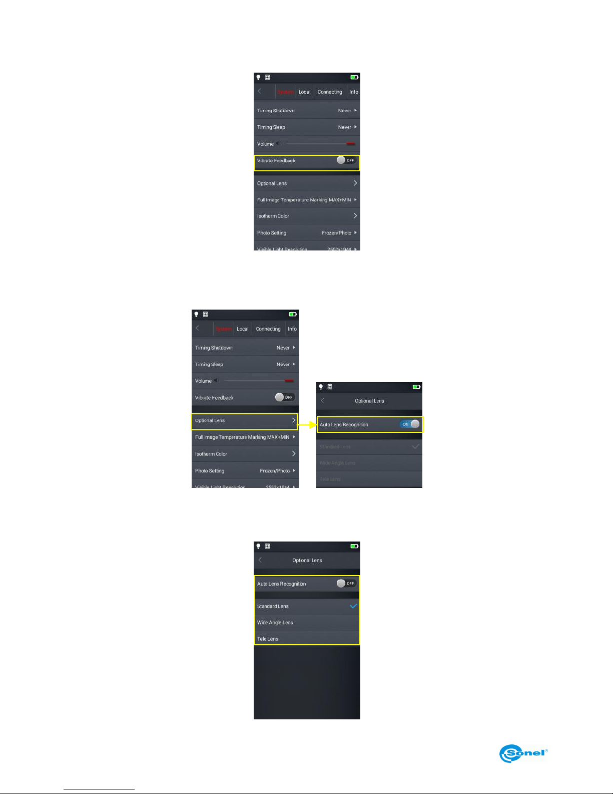
KT-195 ● KT-385 ● KT-200 ● KT-400 – USER MANUAL
42
6.10 Vibrate feedback
Activate or deactivate the vibration feedback.
6.11 Automatic lens recognition
Automatic lens recognition is enabled by default, the camera automatically sets the settings for the
lens used. Manual selection of the lens is possible.
6.11.1 Disabling the automatic lens recognition
When automatic lens recognition is turned off, users can manually select a standard, wide-angle or
telephoto lens, according to the characteristics of the lens of their choice.
Page 43
KT-195 ● KT-385 ● KT-200 ● KT-400 – USER MANUAL
43
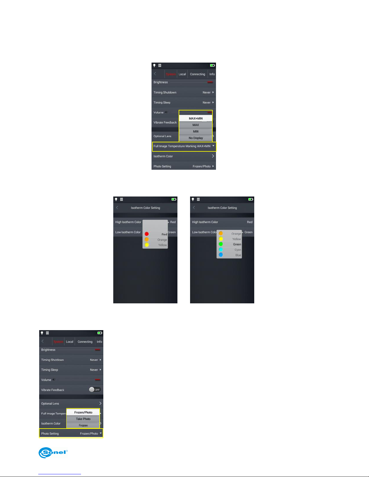
6.12 Indication of the maximum and the minimum temperature on
screen (Full Image Temperature Marking)
In real-time image mode the camera can be set to display the maximum, the minimum or both the
temperatures on screen. By default the min/max temperature indicator is off.
6.13 Isotherm Color
The colors of high/low temperature isotherms are customizable.
6.14 Image taking mode settings (Photo Setting)
The following modes can be selected in this settings menu:
Frozen/Photo: freeze and save: Press the trigger button once to freeze
an image. Press the trigger again to save it.
Take Photo: freeze and save with a single click: Press the trigger button
to freeze and save the image, all at once.
Frozen: freeze only: Press the trigger button to freeze an image. Press
the trigger button again to unfreeze the image. In this mode, an image
can’t be saved.
Page 44
KT-195 ● KT-385 ● KT-200 ● KT-400 – USER MANUAL
44
7 Local settings
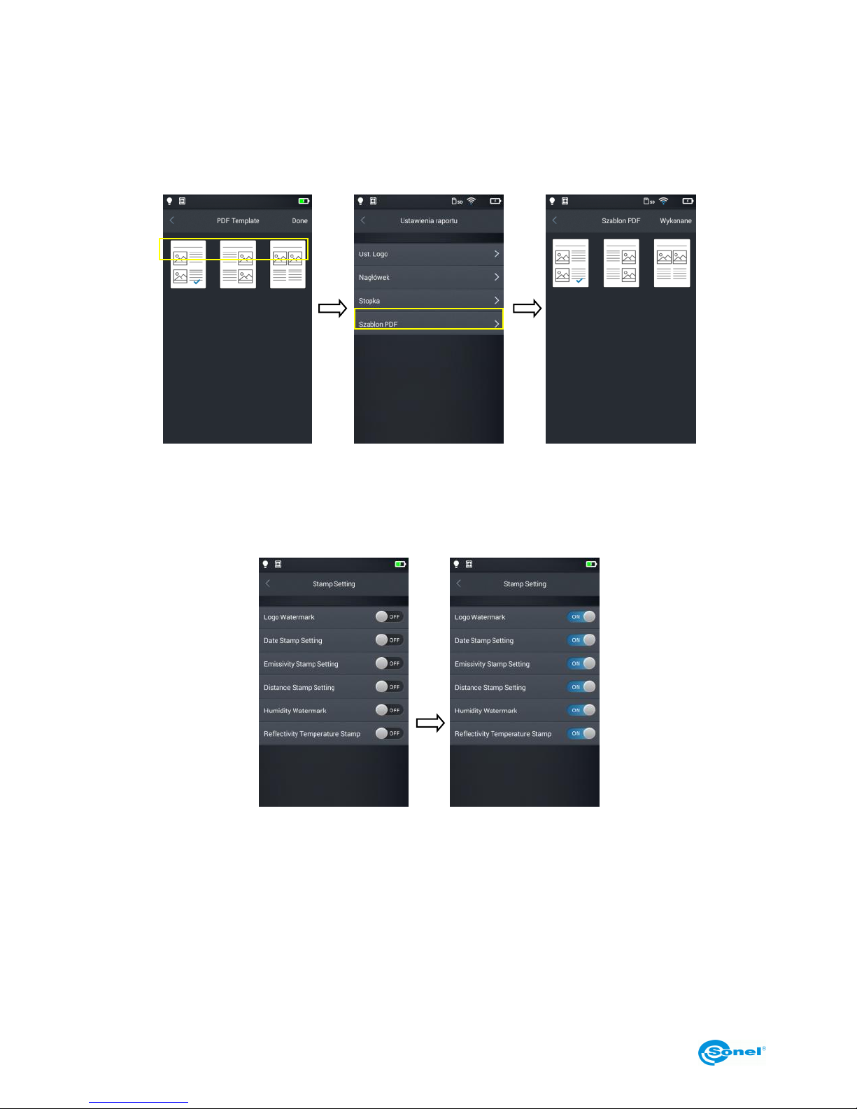
7.1 Report Settings
The following parameters can be modified for a PDF report: logo, header, footer and a PDF template
selection (3 preset templates available).
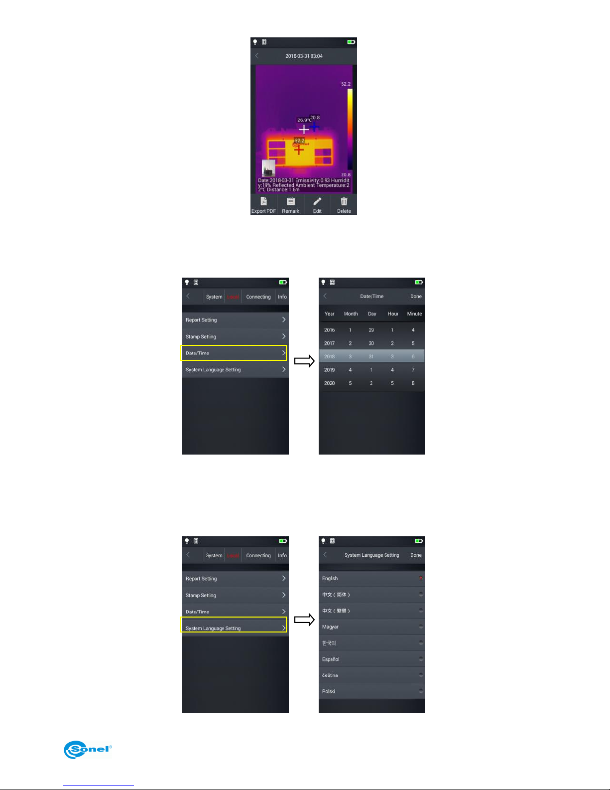
7.2 Stamp settings
1. In stamp settings the following options are available: logo watermark, date stamp, emissivity
stamp, distance stamp, humidity watermark, reflectivity temperature stamp.
2. Once the settings are done, go to real-time mode screen and take a sample picture.
3. Tap the gallery shortcut button, enter the image viewing mode and select the preview of the captured image.
4. All selected watermarks are displayed at the bottom of the preview.
Page 45
KT-195 ● KT-385 ● KT-200 ● KT-400 – USER MANUAL
45
7.3 Date/Time
Set the date and time in the system manually by scrolling their components up/down.
7.4 System Language Settings
Select a language from the list of available languages.
Page 46
KT-195 ● KT-385 ● KT-200 ● KT-400 – USER MANUAL
46
8 Connection settings
8.1 Wi-Fi settings
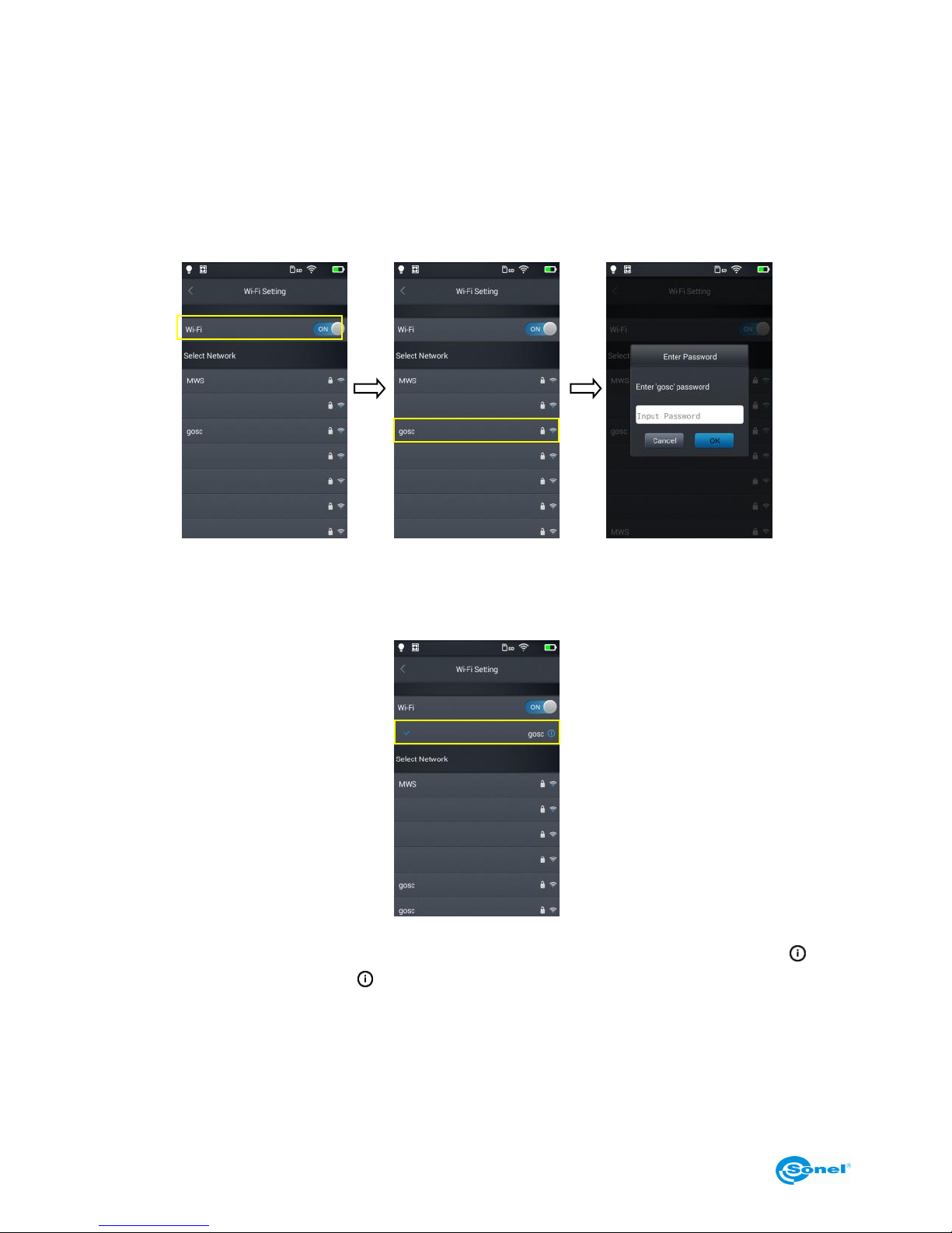
1. Enter Wi-Fi Setting menu.
2. To select a network: tap one of the networks shown in the list and enter the password if required.
3. Type in correct password and press OK.
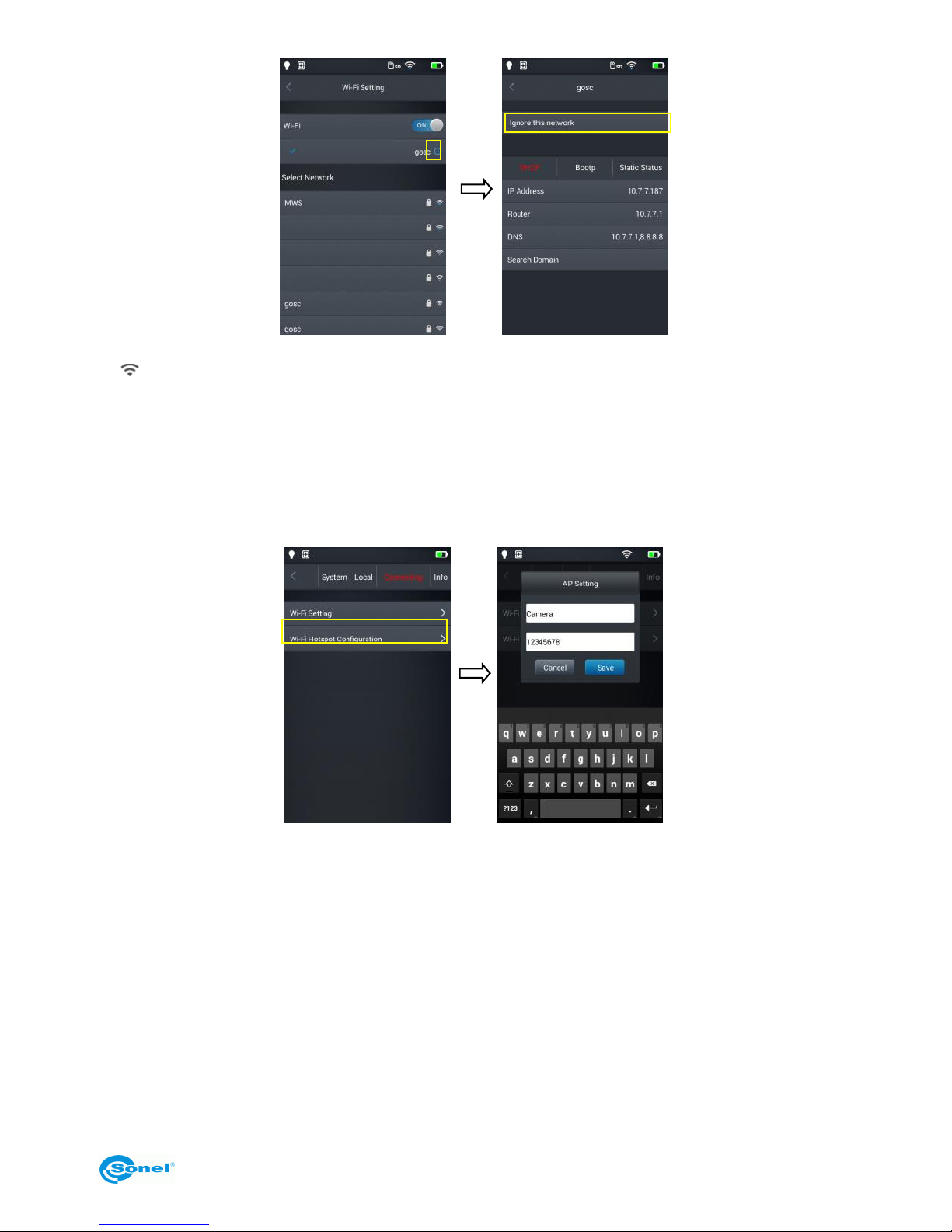
4. The Wi-Fi address setting interface menu can be entered by tapping the More Info Button [ ].
Ignoring the network: Press the [ ] button next to the network name you entered previously and
press Ignore this network.
Page 47
KT-195 ● KT-385 ● KT-200 ● KT-400 – USER MANUAL
47
If [ ] icon appears at the top of the main screen, you are connected to the wireless LAN network
8.2 Wi-Fi Hotspot Configuration
1. Enter the Wi-Fi hotspot configuration menu.
2. In the configuration interface (AP Setting), enter the name of the hotspot, which is set as default
as: "Camera" and the default password is "12345678", then tap the Save button to save the settings.
3. The custom SSID settings and the hotspot access point password are saved successfully.
Page 48
KT-195 ● KT-385 ● KT-200 ● KT-400 – USER MANUAL
48
9 Other settings (Info)
9.1 Firmware update
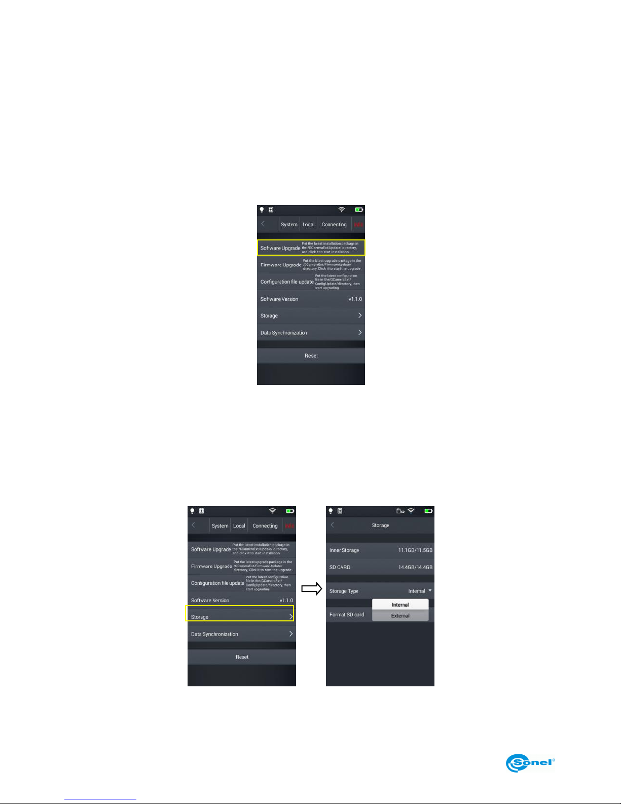
The camera allows to update both the firmware (that runs and governs the operation of the device)
and the Software (user interface). To proceed with the update copy the update file to the appropriate
folder on the SD card as indicated in the camera menu. If an external SD card reader was used, insert the SD card into the camera. Press the upgrade button to initiate the upgrade procedure, and
then follow the on-screen instructions. After the update is complete restart the device.
9.2 Storage
This option mainly shows basic information about the remaining internal and external memory space.
It also allows to select the storage location for files: built-in internal memory or external memory - micro SD card.
Page 49
KT-195 ● KT-385 ● KT-200 ● KT-400 – USER MANUAL
49
9.3 Formatting microSD card
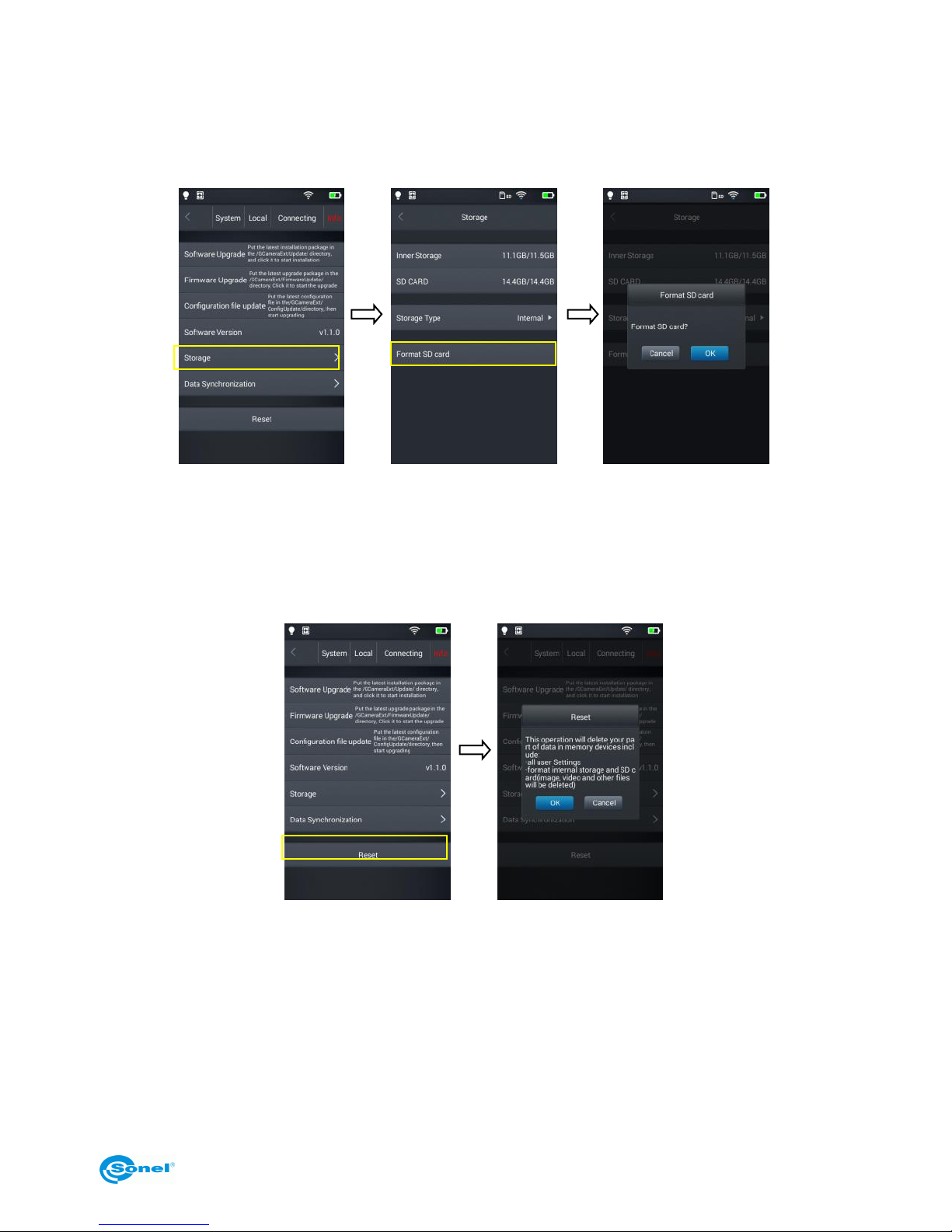
To start formatting select Storage → format SD card, and then press OK. Note that formatting permanently deletes all photos and other data on the memory card. Before formatting, make a backup of
your files if necessary.
9.4 Restoring the default settings
1. Tap Reset and then Ok.
2. Enabling this function will reset the device to its factory settings. Use it carefully.
Page 50
KT-195 ● KT-385 ● KT-200 ● KT-400 – USER MANUAL
50
10 Connection with External Devices
10.1 Port Connection
The camera can be connected to external devices via HDMI and USB cable.
10.2 Micro HDMI Interface
The micro HDMI interface is mainly used to connect an external display, i.e. a monitor, a TV set or a
projector. Please ensure that the target display is equipped with an HDMI interface.
1. Connect the HDMI cable to the thermal imager.
2. Insert the Micro HDMI connector with the <HDMI> symbol towards the front of the device.
3. Connect the HDMI cable to the HDMI IN jack of the external display.
4. Turn on the external display and switch the video input to the selected port.
10.3 USB Interface
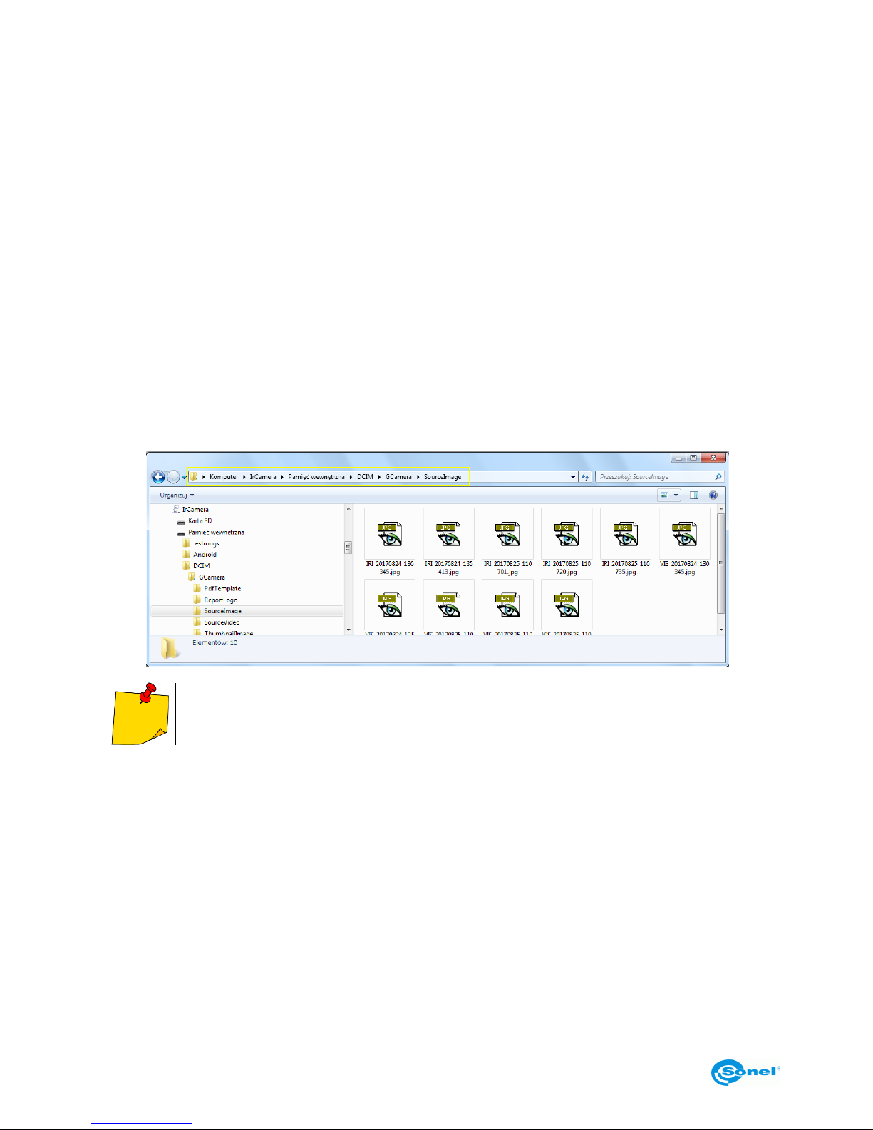
1. Viewing files stored in the internal memory: connect the USB cable to a computer, then open My
Computer to view the internal memory icon. Click it to enter the memory and find the folder containing
the source image. The access path is …IrCamera\InternalMemory\DCIM\GCamera\SourceImage.
File names starting with IRI are infrared images and files names starting with VIS are
visible light images.
2. Browsing files on the microSD card.
In order to save files on the microSD card go to settings – Info → Storage → and select SD CARD,
and now the pictures will be saved on the microSD card.
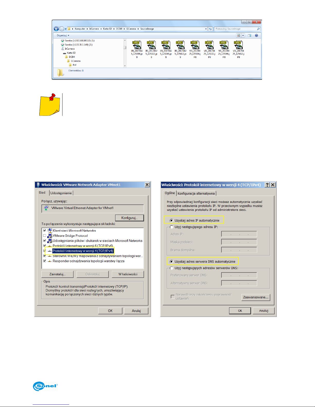
Use the USB cable to connect to the computer, and then open My Computer to view the internal
memory icon. Click it to enter the memory and the path is
… \IrCamera\ SDCard\DCIM\GCamera\SourceImage.
Page 51
KT-195 ● KT-385 ● KT-200 ● KT-400 – USER MANUAL
51
File names starting with IRI are infrared images and files names starting with VIS are
visible light images.
10.4 USB cable connection
1. Connect the camera to PC using USB cable.
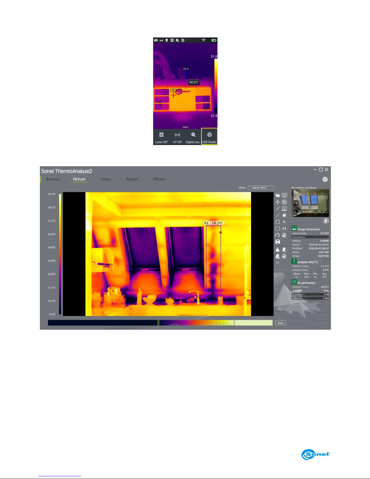
2. A new network connection should appear. If the connection has not been set up automatically, go
to "TCP/IP v4" in the network settings menu, configure "Internet protocol version 4 (TCP/IPv4)" as
"obtain an IP address automatically and "obtain DNS server address automatically" (see images below):
First step
Second Step
Page 52
KT-195 ● KT-385 ● KT-200 ● KT-400 – USER MANUAL
52
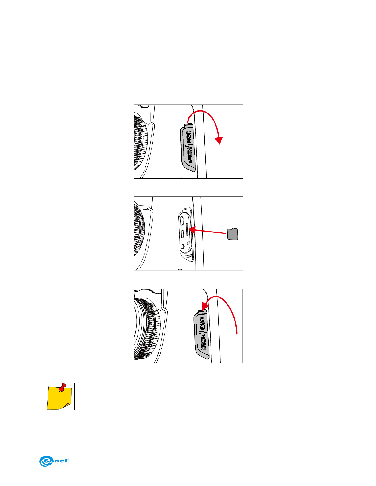
3. Start the real-time video mode,
4. After the camera has been identified by the computer, open the analysis software (see image below).
5. Click the "video" button and select the "On-line" option and then the camera. Then follow the instructions provided with the PC software.
Page 53
KT-195 ● KT-385 ● KT-200 ● KT-400 – USER MANUAL
53
10.5 Installing memory card and lens
The camera supports microSD cards. All photos and videos can be stored on either local or on microSD card. The maximum supported microSD card capacity is 32 GB.
Make sure that the write-protect switch on the memory card, at the top of it, is set to open to allow to
write or erase data.
10.5.1 Installing memory card
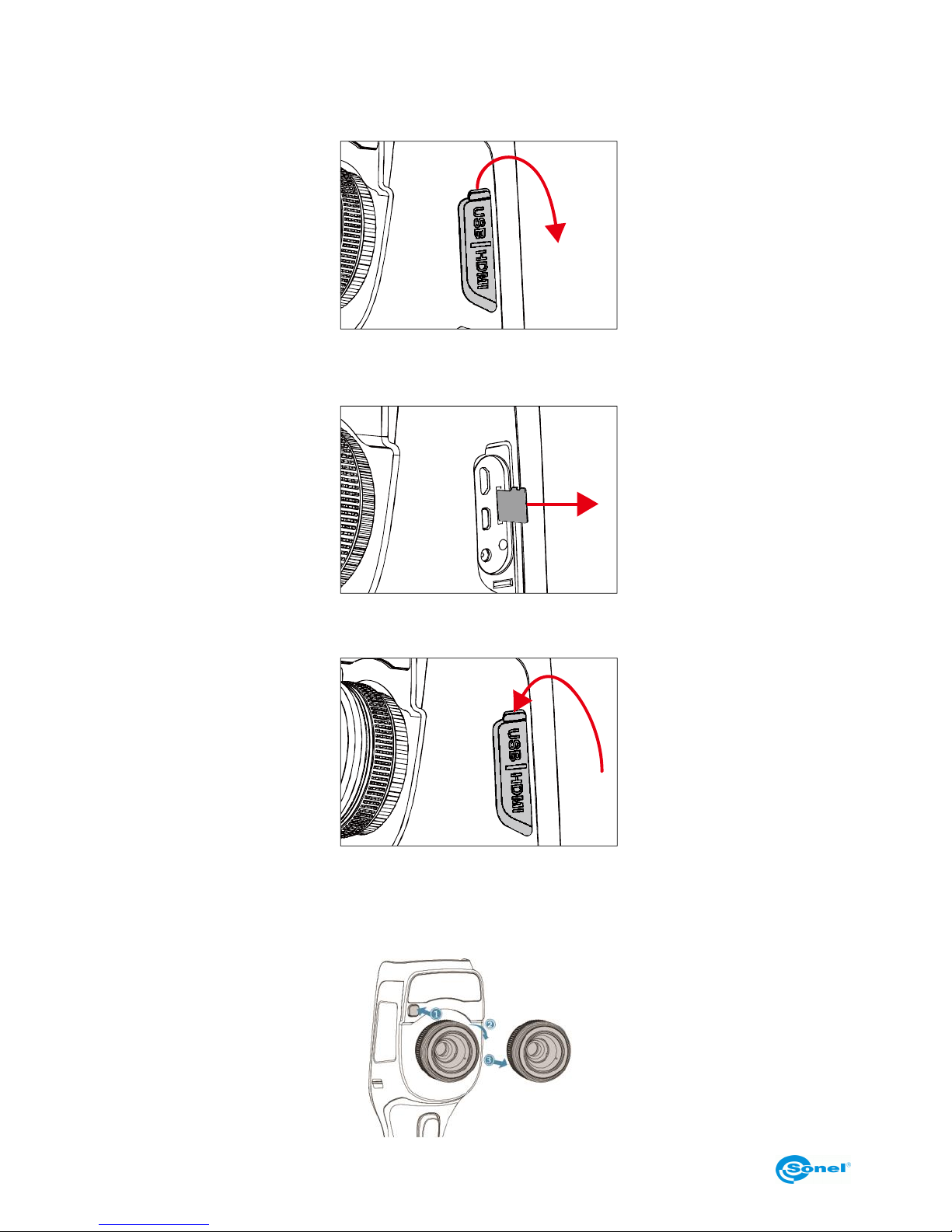
1. Turn off the camera. Slide the slot cover in the direction pointed by the arrow below.
2. Insert the memory card into the SD card slot until a clicking sound is heard.
3. Close the slot cover by sliding it in the direction of the arrow.
4. Turn on the camera.
The number of images that can be stored on a card depends on the size of the data
carrier used.
Page 54
KT-195 ● KT-385 ● KT-200 ● KT-400 – USER MANUAL
54
10.5.2 Removing memory card
1. Turn on the camera and open the slot cover.
2. Gently press the memory card, and then release the pressure.
3. Pull out the card and close the slot cover.
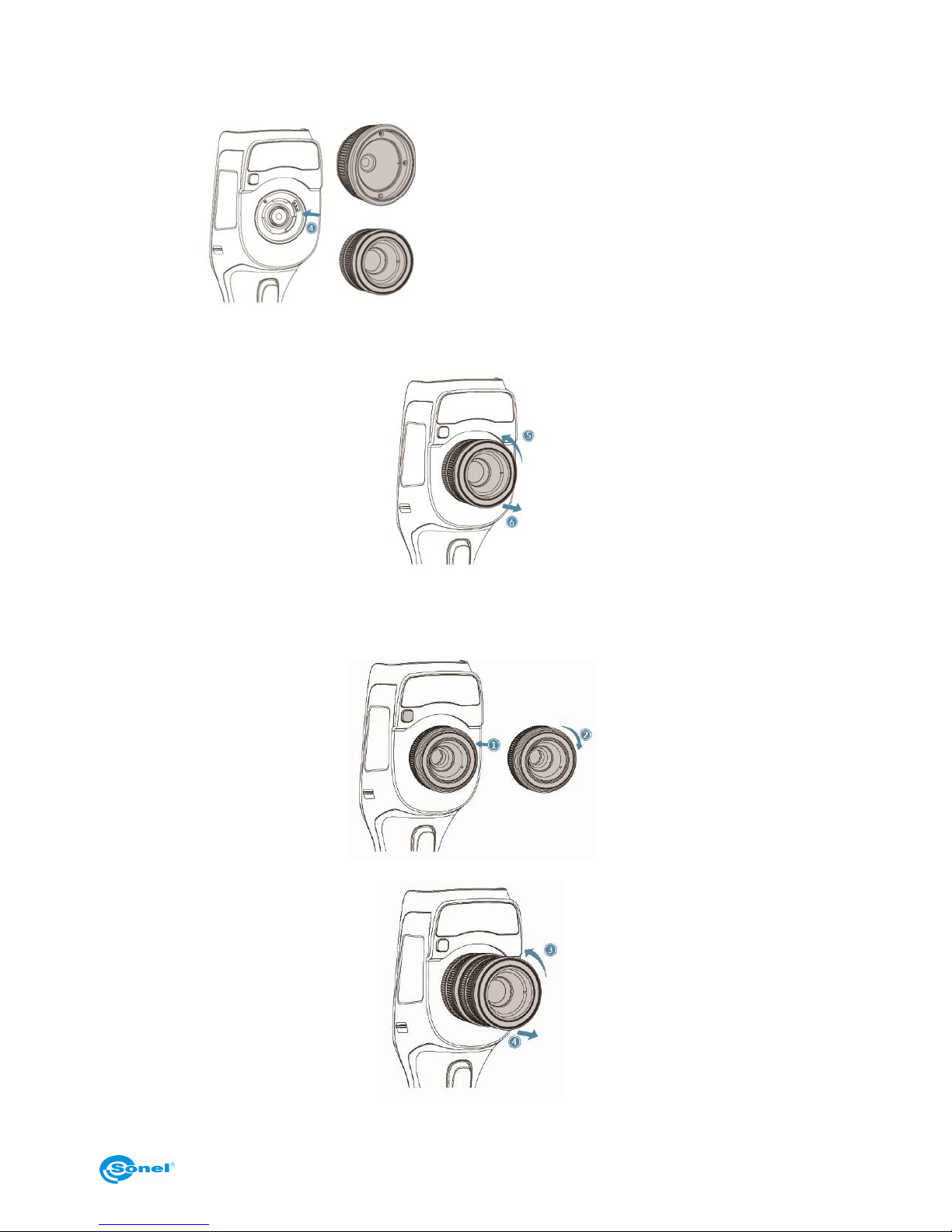
10.6 Installing optional lens
1. Mounting the lens: Press the Split (lens release) button to align the red dot on the back of the
lens with the red dot on the device.
Page 55
KT-195 ● KT-385 ● KT-200 ● KT-400 – USER MANUAL
55
2. Select an appropriate lens, and then rotate it clockwise to mount it.
3. Unmounting the lens: Press the lens release button and align the red dot on the back of the lens
with that on the unit. Then gently remove the lens.
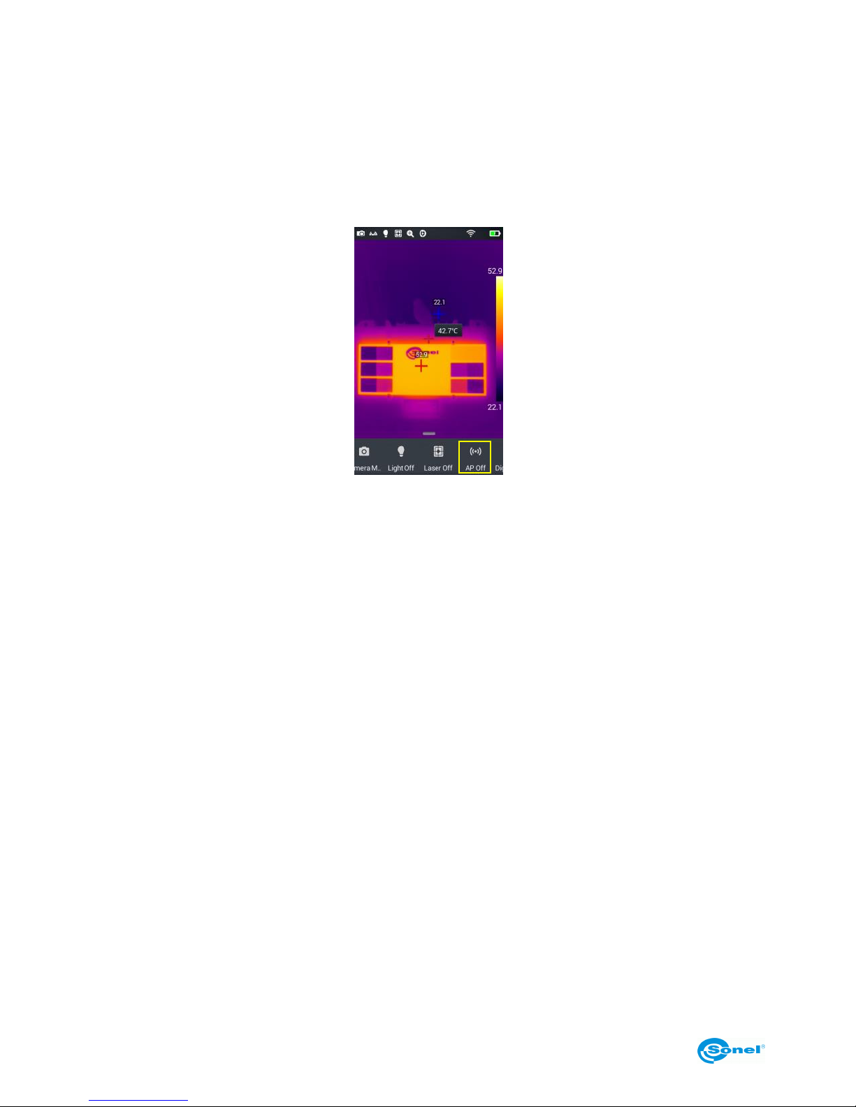
10.7 Installing high temperature filter lens
1. Filter installation: insert a high temperature lens into the threaded standard lens hole, then rotate
the lens clockwise:
2. Removing the lens: rotate the high-temperature lens counter-clockwise to remove it:
(the wide angle lens)
(the tele lens)
Page 56
KT-195 ● KT-385 ● KT-200 ● KT-400 – USER MANUAL
56
10.8 Wireless Access Point (AP) settings
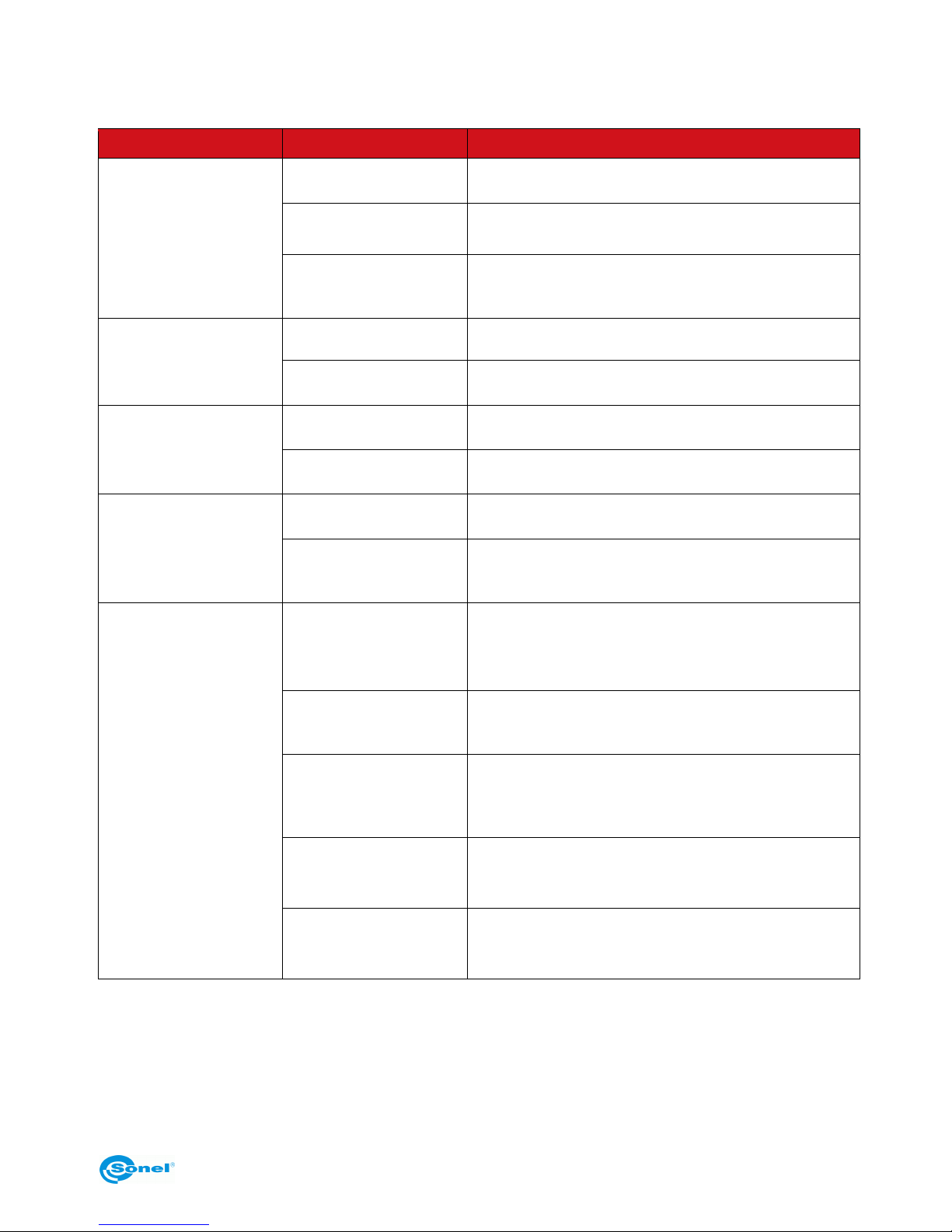
1. Bring up the shortcut menu on the main screen, press the AP Off button to enable the AP function,
the button status will change to AP On (access point on).
2. The status bar will automatically display that the AP function has started and a wireless network
initiated by the network card embedded in the camera is available (factory default SSID: GCamera);
SSID is the name of the network (changeable in the camera menu).
3. To turn off this function tap the AP button again.
The camera with the access point enabled is ready to work with a PC software and mobile devices
applications via the WiFi network.
Refer to the manufacturer's website to find information about the applications.
Page 57
KT-195 ● KT-385 ● KT-200 ● KT-400 – USER MANUAL
57
11 Troubleshooting
Problems
Causes
What to do
The camera doesn’t
turn on
Insufficient battery po-
wer
Recharge the battery and try to use it again
Poor battery contact
Remove the battery, insert it correctly back into the
battery chamber
The external battery
charger plug is not inserted correctly
Pull out the plug and re-insert it
Deviation between the
battery consumption indicator and actual energy consumption
discharged battery
Replace the battery with a fully charged one
the battery has exceeded its expiration date
Insert new battery
IR image is blurry
Focus adjustment has
not been made correctly
Manual focus adjustment needs tweaking to make
the image sharp
steamed up or polluted
lens
Clean the lens with a specialized lens cleaning kit
Visible light image is
blurry
The surroundings are
too dark
Improve lighting
The front part of the device is steamed up or
polluted
Clean the front part with a specialized cleaning kit
The temperature measurement is
not accurate.
Focus adjustment is not
correct
Manually adjust the focus to make the image clear
and then read the temperature
Temperature measurement parameters are
not set properly
Change the parameter setting or restore the default
parameters
The auto calibration
procedure has not been
performed for a prolonged period of time
Perform the auto calibration procedure
Temperature measurement starts immediately
upon start-up
To ensure the best accuracy of the temperature
measurement, we recommend to start the temperature measurement 5-10 minutes after start-up
Long time since the last
factory calibration
To ensure accurate temperature measurements, we
recommend to periodically send back the thermal
imager for calibration (once a year)
Page 58
KT-195 ● KT-385 ● KT-200 ● KT-400 – USER MANUAL
58
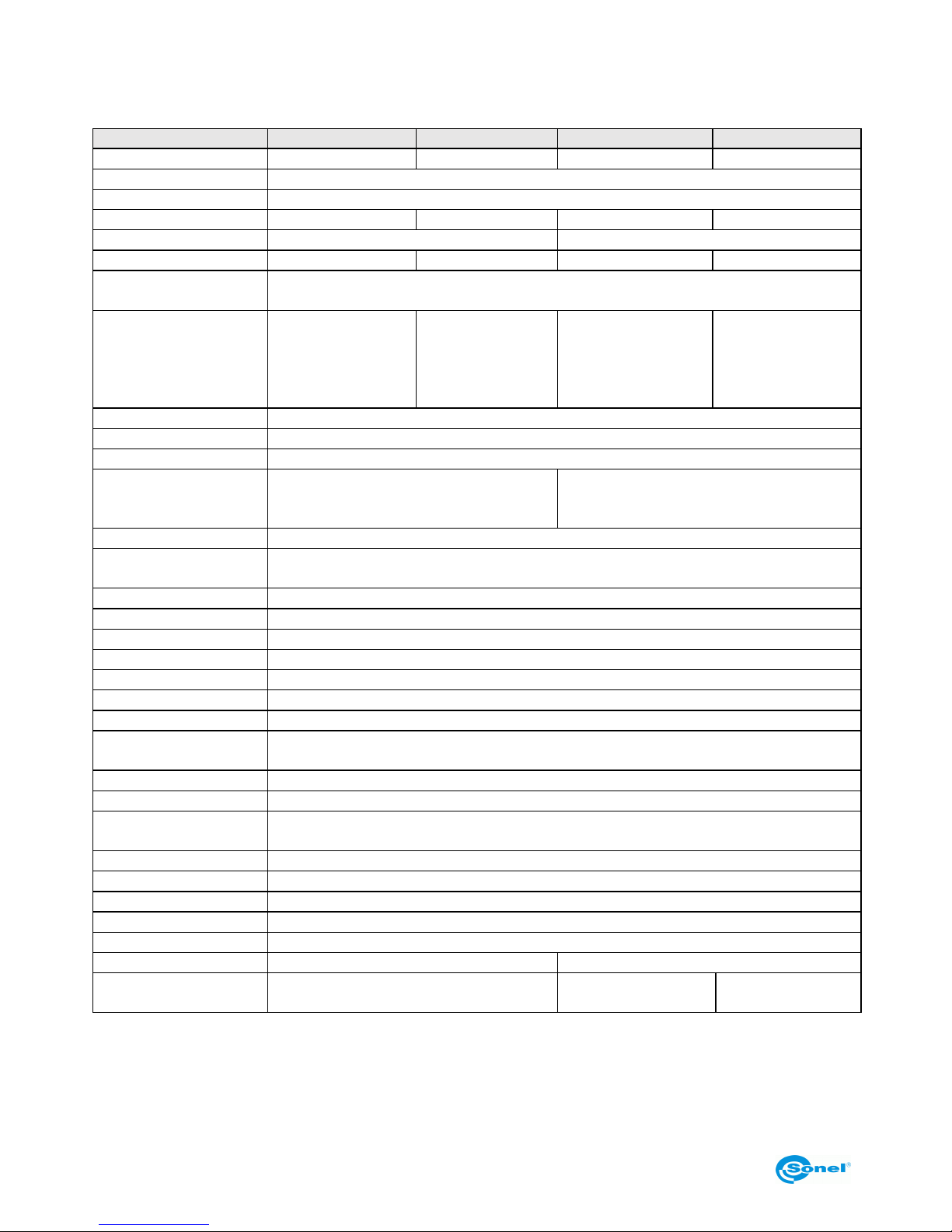
12 Specifications
Model
KT-195
KT-385
KT-200
KT-400
Detector resolution
192 x 144
382 x 288
192 x 144
382 x 288
Spectral range
8~14 µm
Pixel size
25 µm
Thermal sensitivity
50 mk
45 mk
50 mk
45 mk
Focus
Fixed
Manual
IFOV (standard lens)
3.45 mrad
1.29 mrad
3.45 mrad
1.29 mrad
min. focus distance
(standard lens)
0.5 m
Lens (field of view/focal
length)
-
-
37.8° x 28.8°/7 mm
(optional:
14.4° x 10.8°/19 mm)
28.4° x 21.5°/19 mm
(optional:
57.0° x 45.0°/8.8 mm
and
13.7° x 10.3°/40 mm)
Display
4", high brightness, touch screen LCD
Image modes
IR / Visual / Infrafusion MIF / PiP
Digital Zoom
1.1...4
Temperature range
Filter 1: -20°C...+150°C
Filter 2: +150°C...+650°C
Filter 1: -20°C...+150°C
Filter 2: +150°C...+650°C
Filter 3: +650°C…+1500°C (optional)
Accuracy
±2°C or 2% of reading (for ambient temperature from 10°C to 35°C and object temp. 0°C)
Image analysis modes
5 points, 2 lines, 5 areas. Temperature indication: min, max, average. Isotherm. Temperature
difference. Temperature alarm. Dew point.
Palettes
8
Emissivity coefficient
Selectable from 0.01 to 1.00 or from the list of materials.
Measurement adjustment
Adjustable distance, relative humidity, ambient temperature (reflected)
File format
JPG
IR image annotations
Voice (60 s), text, sketch, photo.
Reports module
PDF reports, report printing through Wi-Fi
Video file format
AVI, IRV (including temperature information)
Built-in features
Visual camera 5 MPix, LED flashlight, laser pointer, microphone, speaker.
Wireless communication
Wi-Fi
Interface
microSD card slot, mini HDMI, micro USB 2.0
Power Supply
Li-ion battery (over 4 h continuous operation), built-in charger, AC adapter 110-230 V,
(50/60 Hz) / 12 V
Operating Temperature
-10°C...+50°C
Storage Temperature
-40°C...+70°C
Humidity
10% … 95%
Shock/Vibration
30 g 11 ms (IEC 60068-2-27 / 10 Hz ~ 150 Hz ~ 10 Hz 0.15 mm (IEC 60068-2-6)
Encapsulation
IP54
Weight
approx. 0,74 kg (with battery)
approx. 0,84 kg (with battery)
Dimensions (including
standard lens and battery)
274 mm x 97 mm x 78 mm
274 mm x 106 mm x 78
mm
274 mm x 110 mm x
78 mm
Page 59

KT-195 ● KT-385 ● KT-200 ● KT-400 – USER MANUAL
59
13 Examplary Emissivity Coefficient Values
aluminum ................................ ................. 0.05
aluminum Rough ...................................... 0.07
Aluminum oxidized ................................... 0.25
asphalt ..................................................... 0.90
asbestos board ....................................... 0.96
asbestos (fiber) ........................................ 0.78
akelite ...................................................... 0.93
bronze: dull ............................................ 0.22
bronze: polished ..................................... 0.10
bronze: rough ......................................... 0.55
brick: glass.. rough ................................. 0.85
brick: fireproof. rough .............................. 0.94
cement .................................................... 0.54
cement (concrete .................................... 0.90
chrome .................................................... 0.15
chrome polished ..................................... 0.10
tin ............................................................ 0.09
zinc .......................................................... 0.05
brick red ................................................... 0.93
paint: oil ................................................... 0.94
clay: fired ................................................. 0.91
clay .......................................................... 0.40
graphite .................................................. 0.85
ground: frozen ......................................... 0.93
rubber ...................................................... 0.93
cobalt ...................................................... 0.18
quartz ...................................................... 0.93
lacquer white .......................................... 0.87
lacquer polished black ............................ 0.87
lacquer dull black .................................... 0.97
lacquer silver .......................................... 0.31
ice ........................................................... 0.97
magnesium .............................................. 0.12
copper: oxidized ...................................... 0.65
copper: oxidized black ............................ 0.88
copper: polished ..................................... 0.07
copper: polished annealed ............ 0.01... 0.02
brass ...................................................... 0.10
brass: oxidized ........................................ 0.61
nickel : polished ...................................... 0.05
lead: polished ......................................... 0.08
lead: grey ................................................ 0.28
lead: oxidized ........................................... 0.63
paper white ............................................. 0.90
paper black glossy .................................. 0.90
paper black dull ...................................... 0.94
paper: tarred ........................................... 0.92
plastic: black ........................................... 0.95
platinum .................................................. 0.10
porcelain: glazed ..................................... 0.92
mercury .................................................. 0.10
lampblack ............................................... 0.96
silver ....................................................... 0.03
steel: galvanized ..................................... 0.28
steel: oxidized ......................................... 0.88
steel: rolled freshly .................................. 0.24
steel: rolled ............................................. 0.56
steel: rough ............................................. 0.96
steel: rusty red ........................................ 0.69
steel nickeled .......................................... 0.11
glaze ....................................................... 0.90
glass ....................................................... 0.92
glass dull ................................................ 0.96
snow ....................................................... 0.80
tape insulation ........................................ 0.95
fabric ...................................................... 0.85
titanium ................................................... 0.30
carbon .................................................... 0.90
charcoal powder ..................................... 0.96
tungsten.................................................. 0.13
tungsten: oxidized ................................... 0.11
gold ........................................................ 0.02
iron: glossy ............................................. 0.16
iron: heat rolled ....................................... 0.77
iron: oxidized .......................................... 0.74
iron: polished .......................................... 0.23
iron and steel: oxidized ........................... 0.85
cast: raw casting ..................................... 0.81
cast: polished ......................................... 0.21
The given values may vary depending on the conditions.
Page 60
KT-195 ● KT-385 ● KT-200 ● KT-400 – USER MANUAL
60
14 Cleaning and maintenance
NOTE!
Use the below specified methods of maintenance only.
Camera enclosure - all surfaces, except for optical elements of the camera, can be cleaned with a
soft and moist cloth with generally available mild detergents. Do not use any solvents or cleaning
agents that could scratch the enclosure (powder, paste, etc.). During cleaning, the camera must be
turned off.
Due to the applied anti-reflective coating, optical lens are the most sensitive and at the same time the
most expensive part of the camera (the lens is of key importance to radio-metric capabilities of the infrared system). Therefore it is important to close the protective lens cover after each use of the camera. Optical surfaces should be cleaned only, when they are visibly fouled. Do not touch exposed
surfaces of optical lens with fingers, be-cause fouling left with fingerprints can be harmful to coatings
and glass of the lens.
Chemical agents must not be used for cleaning the optical viewfinder, and particularly op-tics and accessories of the camera. Use a clean, dry and soft cloth for cleaning the body of the viewfinder; for
cleaning the lens, use only the supplied lens cleaning cloth.
15 Calibration
In order to ensure the accuracy and reliability of the thermal imaging camera it is recommended to
calibrate the instrument once every 12 months.
For detailed information related to laboratory services call +48 74 85 83 879 or send an inquiry email
to [email protected].
NOTE!
The KT series thermal imaging cameras do not comprise any parts serviceable by the
user. Do not attempt to dismantle or modify the camera on your own. Opening the
instrument voids the warranty.
16 Storing
When storing the instrument, observe the following guidelines:
make sure the camera and its accessories are dry,
when storing the camera for a prolonged time, remove the batteries,
allowed are storage temperatures specified in technical specifications,
in order to avoid complete discharging of rechargeable batteries during prolonged storage,
charge them once in a while.
Page 61

KT-195 ● KT-385 ● KT-200 ● KT-400 – USER MANUAL
61
17 Accessories
17.1 Standard accessories
Standard bundle supplied by the manufacturer includes:
2 x Li-Ion 7,4 V 3,2 Ah rechargeable battery for thermal imagers KT-195 / 200 / 385 / 400 –
WAAKU24
MicroUSB cable for data transmission – WAPRZUSBMICRO
Hand strip for KT-195 / 200 / 385 / 400 – WAPOZPAS4
HDMI cable – WAPRZHDMI
Protective gloves (for operating the touchscreen) – WAREK1
SD card 16 GB – WAPOZSD16
Power supply adaptor Z13 for KT-195 / 200 / 385 / 400 / 670 / 650 / 560 – WAZASZ13
User manual and CD with dedicated software.
17.2 Additional accessories
Additional accessories:
External battery
charger for
KT-195 / 200 / 385
/400
WAZASZ18
Lenses
IR 40 mm tele for KT-400
(13.7° x 10.3°) – WAADAO40
IR 19 mm tele for KT-200
(14.4° x 10.8°) – WAADAO19
High-temperature filter from 1500°C
for KT-200, KT-400 – WAADAOF2
Soft carrying bag
M-11
WAFUTM11
* Illustrative pictures - the final appearance of the purchased accessories may differ from the image in the pictures.
Page 62
KT-195 ● KT-385 ● KT-200 ● KT-400 – USER MANUAL
62
18 Dismantling and disposal
Used-up electrical or electronic equipment must be collected selectively, i.e. must not be mixed with
waste of other types.
Used-up electronic equipment must be delivered to an appropriate collection centre in ac-cordance
with regulations related to used-up electrical or electronic equipment.
Before delivering the equipment to the collection centre do not attempt to dismantle any of its parts.
NOTE!
Follow local regulations related to disposing of packaging, used-up batteries and rechargeable batteries.
19 Manufacturer
The manufacturer and provider of warranty and post-warranty services for this instrument is:
SONEL S.A.
Wokulskiego 11
58-100 Świdnica
Poland
tel. +48 74 858 38 60
fax +48 74 858 38 09
e-mail: [email protected]
web page: www.sonel.pl
NOTE!
Only the manufacturer is authorized to perform service repairs.
Manufactured in PRC.
Page 63
KT-195 ● KT-385 ● KT-200 ● KT-400 – USER MANUAL
63
20 Laboratory services
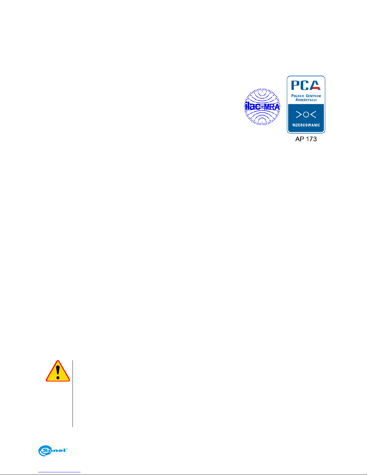
SONEL Testing and Calibration Laboratory has been accredited by the Polish Center of Accreditation for the calibration of measuring instruments AP 173 in the following field - electrical properties
in DC and LF circuits: voltage and current (DC), voltage and current (AC), resistance (DC), electrical
power.
SONEL Testing and Calibration Laboratory offers validation and
calibration services for the following instruments used for measuring
electrical and non-electrical parameters. The following instrument
types are calibrated:
meters for measurements of electrical properties and parame-
ters of power networks:
o voltage meters,
o current meters (including clamp meters),
o resistance meters,
o insulation resistance meters,
o earthing resistance meters,
o short-circuit loop impedance meters,
o RCD meters,
o power quality analyzers,
o electrical equipment safety testers,
o active and passive electrical power meters for alternating current,
o multimeters,
o multifunction meters covering the functions of the above-mentioned instruments,
standards of electrical properties:
o calibrators,
o resistance standards,
instruments for the measurements of non-electrical:
o pyrometers,
o thermo-imaging cameras.
o lux meters.
The Calibration Certificate is a document specifying the relationship between the standard and the
instrument's indication with indication of measurement uncertainty.
According to ILAC-G24:2007 „Guidelines for the determination of calibration intervals of measuring
instruments”, SONEL S.A. recommends periodical metrological inspection of the instruments it manufactures no less frequently than once every 13 months.
For new instruments provided with the Calibration Certificate or Validation Certificate at the factory,
re-calibration should be performed within 13 months from the date of purchase, however, no later
than 25 months from the date of purchase.
ATTENTION!
The person performing the measurements should be absolutely sure about the efficiency of the device being used. Measurements made with an inefficient meter can
contribute to an incorrect assessment of the effectiveness of health protection and
even human life.
Measurements carried out in an accredited calibration laboratory (with competences
con-firmed by PCA), it is certain that they were made in accordance with applicable
standards, procedures, including the best reliability.
Page 64

KT-195 ● KT-385 ● KT-200 ● KT-400 – USER MANUAL
64
NOTES
 Loading...