

Page 1

OPERATING MANUAL
KT-384
THERMAL IMAGER
SONEL S. A.
ul. Wokulskiego 11
58-100 Świdnica
Poland
Version 1.02 10.11.2011
Page 2
SONEL KT-384 THERMAL IMAGER
2
The KT-384 thermal imager, or thermal imaging camera, meets the requirements of current EU directives related to safety and electromagnetic compatibility.
Thank you for buying our thermal imager. The KT-384 camera is a state-of-the-art, high
quality measurement instrument providing easy and safe use. Familiarization with this
manual will allow for avoiding errors during measurement and preventing potential problems related to operating the camera.
Products from Sonel S.A. are manufactured under the ISO9001:2008 Quality Management System in
regards to designing, manufacturing and servicing processes.
Due to continuous development of our products, we reserve the right to introduce changes and improvements to the thermal imaging camera and the program described in this manual without prior
notice.
Copyright
© Sonel S.A. 2011. All rights reserved. The present manual may neither be copied, reproduced,
translated nor transferred to any electronic media or in a machine-readable form in part or as a whole
without a prior written permission from Sonel S.A.
Page 3

OPERATING MANUAL
3
TABLE OF CONTENTS
1
SAFETY....................................................................................................................6
2
FUNCTION BUTTONS AND ON-SCREEN MENU............................................8
2.1
A
RRANGEMENT OF BUTTONS
...................................................................................8
2.2
D
ISPLAY
.................................................................................................................8
2.3
A
RRANGEMENT OF INFORMATION ON THE SCREEN
.................................................10
3
OPERATING AND ADJUSTING THE CAMERA ............................................11
3.1
T
URNING THE CAMERA ON/OFF
.............................................................................11
3.2
F
OCUS ADJUSTMENT
............................................................................................11
3.3
Z
OOMING IN (X2, X
4) ...........................................................................................11
3.4
T
EMPERATURE RANGE
..........................................................................................11
3.5
I
MAGE MODES
......................................................................................................13
3.6
M
ANUAL CALIBRATION
.........................................................................................18
3.7
L
ASER POINTER
....................................................................................................18
3.8
LED
FLASHLIGHT
................................................................................................18
3.9
D
EW POINT
..........................................................................................................19
3.10 C
APTURING AND SAVING IMAGE WITH A VOICE ANNOTATION
..................................19
3.11 F
UNCTION SETTINGS
............................................................................................21
3.11.1 Object emissivity settings.............................................................................22
3.11.2 Ambient temperature and temperature alarm settings ................................22
3.11.3 Selecting distance from an object................................................................24
3.11.4 Selecting colour palette ...............................................................................24
3.11.5 Setting relative humidity..............................................................................26
3.11.6 Activation of laser pointer ...........................................................................26
3.11.7 Brightness....................................................................................................26
3.12 C
AMERA SETTINGS
...............................................................................................26
3.12.1 Restoring default settings ............................................................................27
3.12.2 Selecting the user interface language..........................................................28
3.12.3 Selecting the units of temperature ...............................................................28
3.12.4 Setting time and date ...................................................................................28
3.12.5 Selecting lens...............................................................................................28
3.12.6 External display monitor and selecting the type of video signal .................29
3.12.7 Auto-off function (hibernation)....................................................................29
3.13 F
ILES - VIEWING, SETTINGS, INFORMATION, VIDEO MODE
......................................29
3.13.1 Viewing saved images or video files and removal of single files from
memory........................................................................................................30
3.13.2 Deleting all saved images............................................................................31
3.13.3 Video............................................................................................................31
3.13.4 Selecting storage medium............................................................................31
3.13.5 Help .............................................................................................................33
3.13.6 Information about hardware and software versions....................................33
Page 4

SONEL KT-384 THERMAL IMAGER
4
3.14 P
OWER SUPPLY, CHARGING BATTERIES
................................................................. 33
3.14.1 Using the AC power supply adapter ........................................................... 33
3.14.2 Operation on regular/rechargeable batteries............................................. 34
3.14.3 Charging rechargeable batteries................................................................ 34
3.14.4 General rules of using the Ni-MH rechargeable batteries..........................34
4
ACCURATE MEASUREMENT OF TEMPERATURE.................................... 36
5
RECORDING THERMAL VIDEO..................................................................... 37
5.1
R
ECORDING TO THE SD CARD
.............................................................................. 37
5.2
I
NSTALLING CAMERA DRIVER
................................................................................38
5.2.1
Hardware requirements ..............................................................................38
5.2.2
Installation.................................................................................................. 38
5.3
I
NSTALLING THE "SONEL THERMOANALYZE
®
"
SOFTWARE
.....................................41
5.4
C
ONFIGURING THE "SONEL THERMOANALYZE
®
"
SOFTWARE
................................. 41
5.5
R
ECORDING DIRECTLY TO HARD DISK AND PLAYING BACK THERMAL VIDEO
RECORDINGS
...................................................................................................... 43
5.5.1
Real time thermal video ..............................................................................43
5.5.2
Commands available in thermal video mode only ...................................... 45
5.5.3
Saving and analysing data..........................................................................50
6
TRANSMITTING AND ANALYSING DATA ...................................................51
6.1
R
EADING EXTERNAL MEMORY
(SD
MEMORY CARD
)............................................... 51
6.2
R
EADING THE BUILT-IN UFLASH MEMORY
.............................................................51
6.3
A
NALYSING DATA
.................................................................................................52
7
TECHNICAL SPECIFICATIONS.......................................................................53
8
EXAMPLE VALUES OF EMISSIVITY COEFFICIENT................................. 55
9
LISTING OF ON-SCREEN MESSAGES ...........................................................56
10 USE OF ADDITIONAL ACCESSORIES ...........................................................57
10.1 L
ENS
...................................................................................................................57
10.2 W
ORKING IN INTENSIVE LIGHTING CONDITIONS
.................................................... 59
10.3 W
ORKING WITH A TRIPOD
.................................................................................... 59
11 CLEANING AND MAINTENANCE................................................................... 60
12 CALIBRATION.....................................................................................................60
13 STORAGE.............................................................................................................. 60
14 EQUIPMENT.........................................................................................................61
Page 5

OPERATING MANUAL
5
15 DISMANTLING AND DISPOSAL.......................................................................63
16 MANUFACTURER ...............................................................................................63
Page 6

SONEL KT-384 THERMAL IMAGER
6
1 Safety
Before commencing operation of the camera, please familiarize yourself with this manual
thoroughly and follow safety regulations as well as recommendations of the manufacturer.
• Any use of this camera, other than specified in this manual, can lead to damaging the
instrument and cause serious threat to the user.
• The camera must not be used in spaces of special conditions, e.g. in explosive or
flammable atmospheres.
• Use of the camera, which is partially of entirely faulty due to a sustained damage, is
not allowed.
• In case the instrument is not used for a prolonged time, it is necessary to remove the
batteries. Leaving discharged batteries inside the instrument can lead to battery leaks
and damage to the camera.
• The camera must not be used with open or not fully closed battery cover or use a
power supply other than the one supplied with the camera.
• Repairs may be performed by an authorized service shop only.
The KT-384 thermal imaging camera is intended for performing measurements and recording images in infrared radiation. The camera was designed to provide the user with
maximal effectiveness and safety during operation, however observing the following conditions and recommendations is required (in addition to any precautions at a particular
work place or work area):
• During operation, the camera must be held in a stable position.
• Do not use the camera in temperatures exceeding the range of its operational and
storage temperatures.
• The thermal imaging camera must not be directed at high intensity heat radiation
sources, such as the Sun, lasers, welding arc, etc.
• The thermal imaging camera must not be exposed to contact with dust and humidity.
When using the instrument in the vicinity of water, make sure it is properly protected
from splashing.
• When the thermal imaging camera is not used or is prepared for transport, make sure
the instrument and its accessories are stowed in a protective carrying case.
• Do not close ventilation openings or the speaker in the camera body.
• After turning the camera off, wait at least 15 seconds before switching it back on.
• Do not throw, hit or intensively shake the camera or its accessories to avoid damaging
them.
• Do not attempt to open the camera, because this will void the warranty.
• A given SD memory card must be used exclusively with the camera.
• If, during its operation, it is necessary to move the camera from warm to cold place,
and vice versa, e.g. from a room to the outside or the other way around, the camera
must be turned off, and the instrument must be left in the new place for about 20 minutes. Then the camera may be turned on, and its normal operation with accurate tem-
Page 7
OPERATING MANUAL
7
perature measurement may be resumed. Sudden and rapid changes of ambient temperature can cause a temperature measurement error, or even a damage to the infrared sensor.
• Calibration of the Focal Plane Array detector (FPA ): in order to ensure precise meas-
urement of temperature the FPA detector has been calibrated in various temperatures:
7°, 17°, 27°, 37°. When, for example, the camera is turned on in the temperature of 0°,
after a certain time its own temperature (temp. of the detector) rises gradually, and
when it exceeds 7°, an automatic, approx. 30 sec. l ong adjustment of the FPA detector
will occur. During adjustment, the camera will not respond to the user's actions.
This will be repeated, when the temperature of the camera exceeds 17°, etc.
Besides that, during operation, the camera performs periodic, 5 seconds long auto-
calibration, signalled with the symbol in the top left corner of its display. Autocalibration can also be run manually at any time, as described in section 3.6
NOTE!
Only standard and supplementary accessories listed in chapter "Equipment"
must be used. Using other accessories does not guarantee proper operation
and can cause a damage to the camera.
NOTE!
Due to continuous development of the instrument software, the appearance
of the display can differ slightly from what is presented in this manual.
NOTE!
The KT-384 thermal imaging camera does not comprise any parts serviceable
by the user. Never attempt to disassemble or modify the camera. Opening the
instrument voids its warranty.
NOTE!
The laser pointer used in the camera can constitute a threat of eyesight dam-
age in case of direct contact!
DO NOT DIRECT THE LASER BEAM TOWARDS PERSONS OR ANIMALS!
Remember that the laser beam can reflect off shiny surfaces.
NOTE!
To maintain required parameters of rechargeable batteries, unused re-
chargeable batteries should be charged every 3 months. If the device is not
used for a longer period of time, the batteries must be removed from it and
stored separately.
Page 8
SONEL KT-384 THERMAL IMAGER
8
2 Function buttons and on-screen menu
2.1 Arrangement of buttons
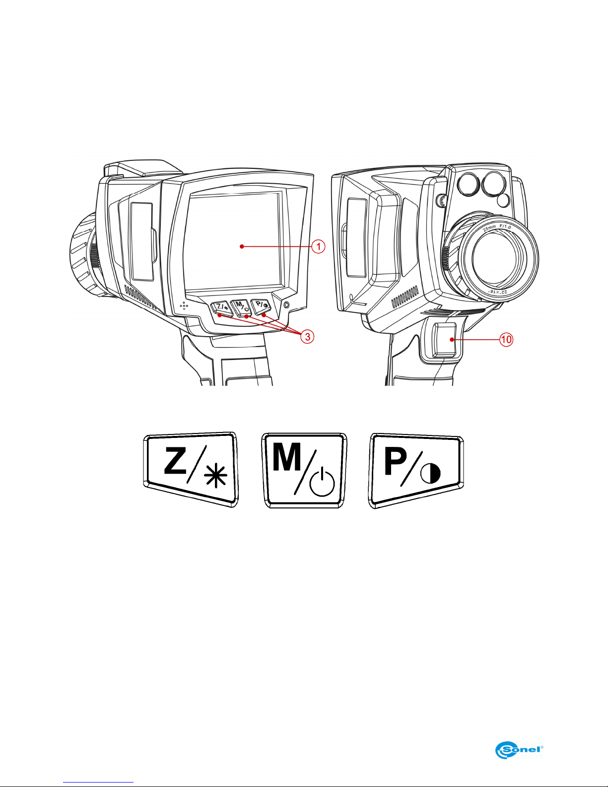
Functions of the camera are accessible through buttons (3) located under the LCD display
(1), as well as a trigger switch (10):
The function buttons (3) are arranged as follows:
2.2 Display
During operation of the camera, the infrared image is shown on the screen (1) in real time
(the image is refreshed 50/60 times per second). In the right part of the screen, there is a
temperature range bar with corresponding colours for displaying. The value of temperature at the central point of the screen is always displayed as well as either the highest or
the lowest temperature of the marked point in the observed area, depending on the selected temperature alarm mode (min. or max. - see section 3.11.2):
Page 9
OPERATING MANUAL
9
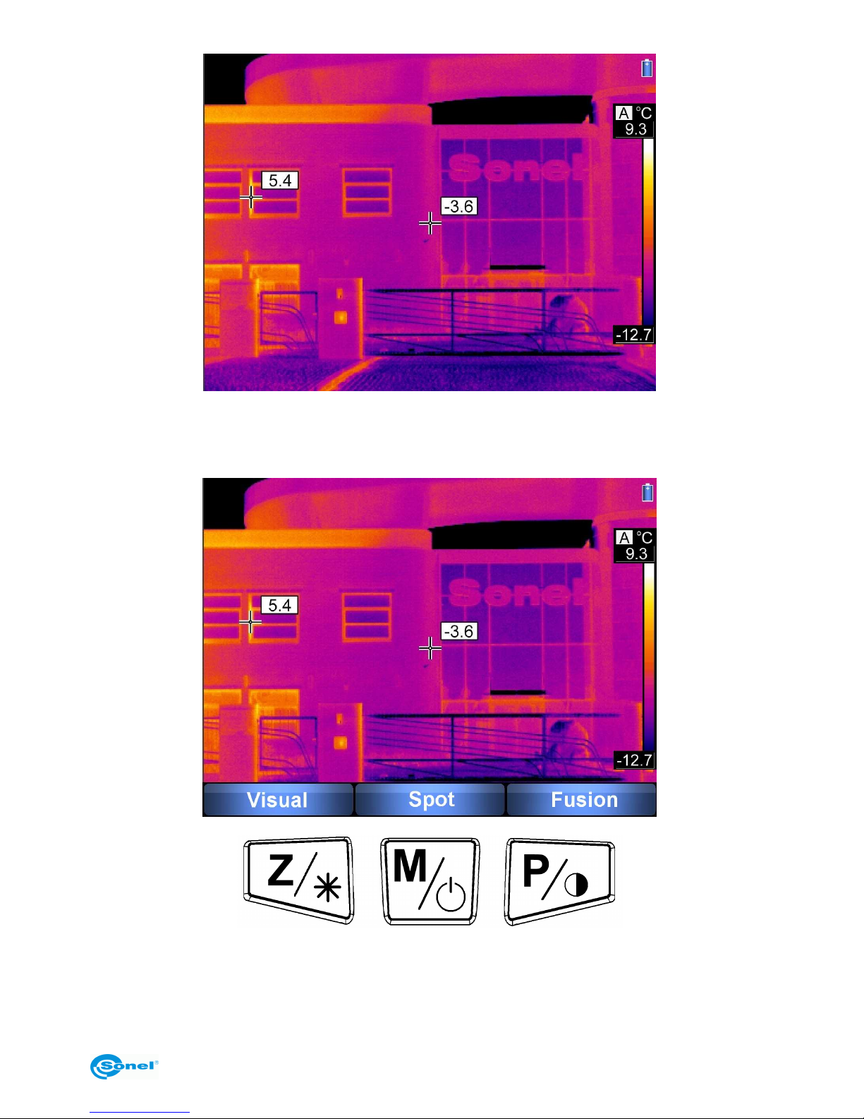
After activating any function or performing a measurement, in the bottom part of the
screen a menu appears, where each of the available functions is executed with one of the
corresponding buttons:
In the above example, the left button marked as Z corresponds to the "Visual" command,
the central button marked as M corresponds to the "Spot" command, and the right button
marked as P corresponds to the "Fusion" command.
Page 10
SONEL KT-384 THERMAL IMAGER
10
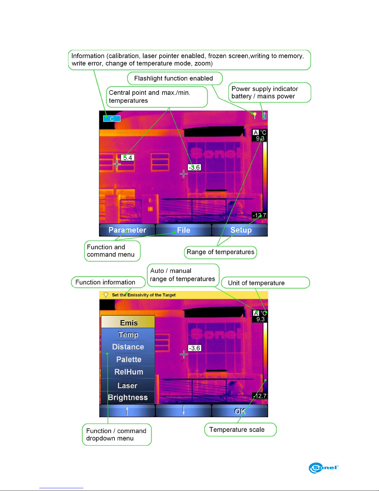
2.3 Arrangement of information on the screen
Page 11
OPERATING MANUAL
11
3 Operating and adjusting the camera
3.1 Turning the camera on/off
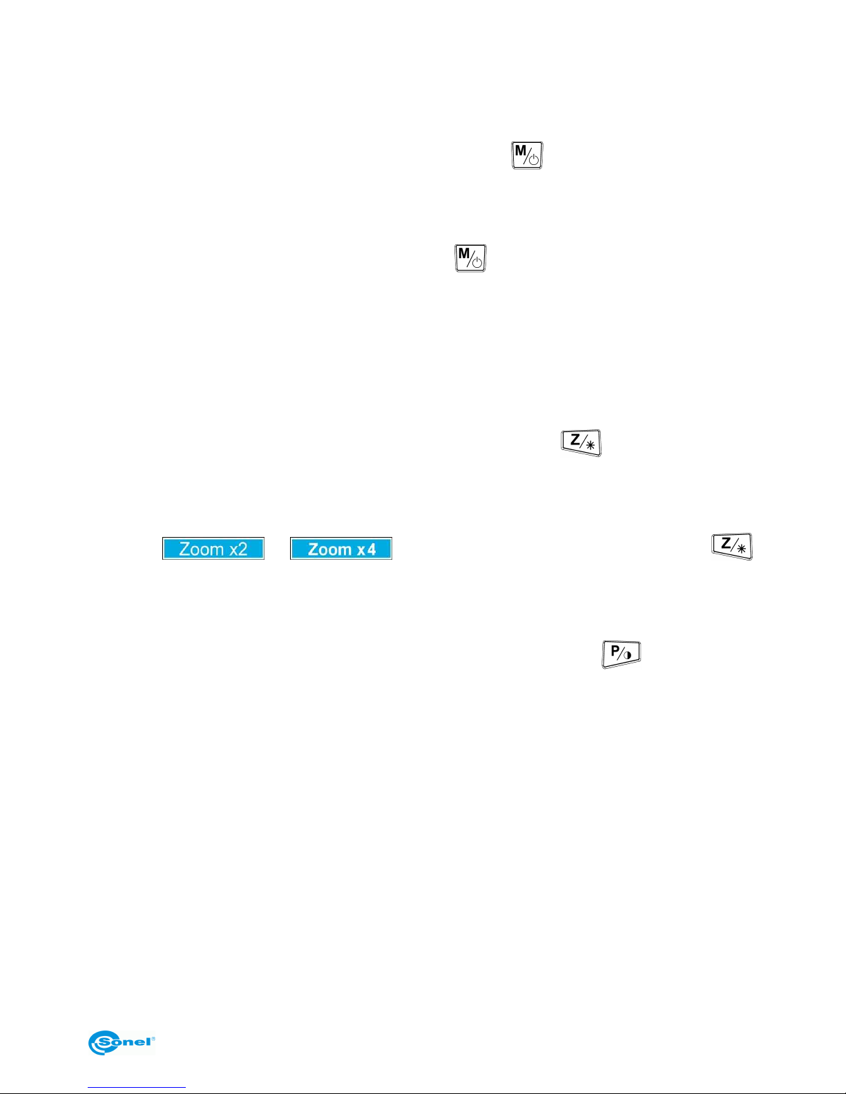
In order to turn the camera on, press and hold the button for longer than 3 seconds.
A welcome logo will be displayed, followed by the results of self-test of the instrument, and
after the completion of testing, the camera is ready to be used and enters the mode of infrared image display in real time.
To turn the camera off, press and hold the button until the display turns off.
3.2 Focus adjustment
After directing the camera towards the examined object, turn the lens (9) to set the best
focus of image.
3.3 Zooming in (x2, x4)
When no menu is displayed on the screen, pressing the button will cause switching
to the zoom mode - the image on the screen will be digitally magnified two times. Pressing
the button again will switch the image to the x4 zoom mode. In these modes, focus can be
adjusted precisely - but no other functions are accessible. The "zoom" modes are sig-
nalled by or in the top left corner. Pressing the button
restores normal image mode.
3.4 Temperature range
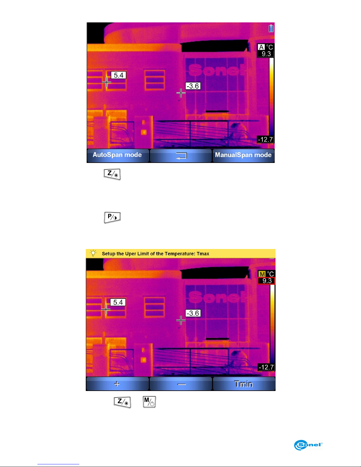
When no menu is displayed on the screen, press and hold the button for 2 s.
Page 12
SONEL KT-384 THERMAL IMAGER
12
Pressing the button selects automatic adjustment of displayed temperature range the minimal and maximal temperatures will be automatically adjusted by the instrument
while the measurement is performed, depending on the range of temperatures detected in
the observed area.
Pressing the button causes entering manual adjustment of temperature range. Selecting this mode causes entering a menu of setting the upper limit of the temperature
Tmax:
By pressing the button or , the upper limit of the displayed temperature range
is increased/decreased (the changed value is additionally marked by a red frame). Press-
Page 13
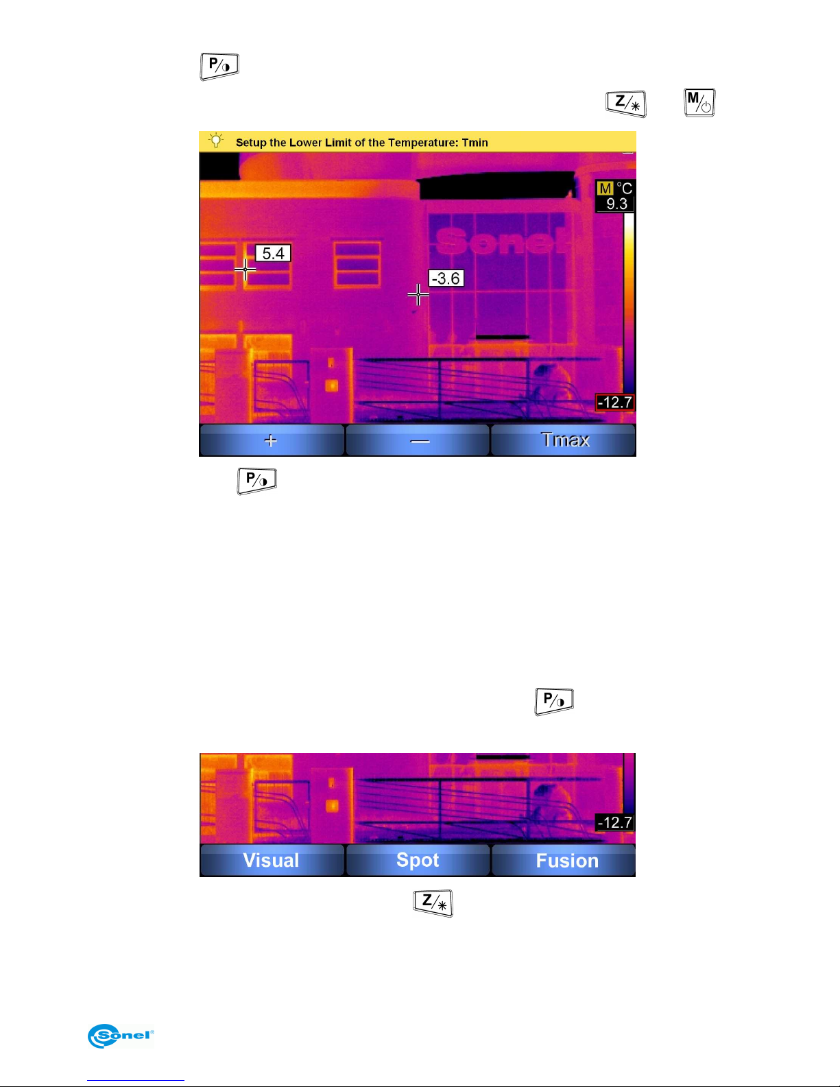
OPERATING MANUAL
13
ing the button causes switching over to setting the lower limit of the temperature
range, which can, just like the upper limit, be adjusted with the buttons and :
Pressing the button causes switching over to setting the upper limit of the temperature range.
The manually selected temperature range is confirmed by pressing the trigger switch (10).
Information about the choice of the automatic or manual range will be displayed afterwards for 2 seconds in the top left corner of the screen. Additionally, current mode is indicated as "A" (auto mode) or "M" (manual mode) displayed over the upper temperature
limit value.
3.5 Image modes
When no menu is displayed on the screen, press the button briefly. A screen is displayed allowing for selecting one of the 3 image modes:
1. After selecting the "Visual" mode (button
) the camera will display only visible image (additional information is shown in the top part of the screen). By pressing the trigger
switch (10), operation in infrared mode is resumed.
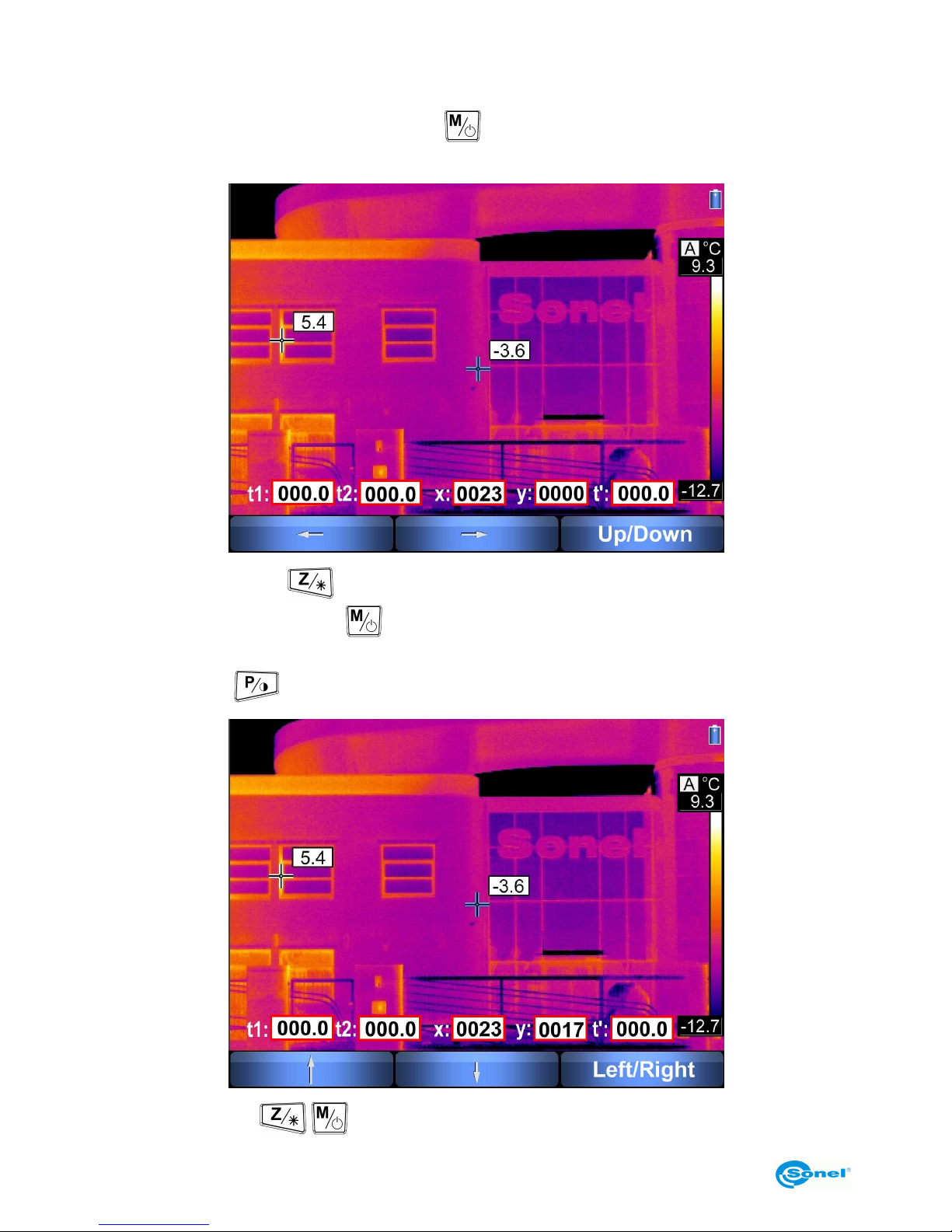
2. The "Spot" function allows for changing the position of the spot (by default located in
Page 14
SONEL KT-384 THERMAL IMAGER
14
the centre of the screen), for which the temperature value is always measured and shown,
and show the exact difference between results of two succesive measurements. After se-
lecting this function (pressing the button ), the screen assumes the following appearance:
Pressing the button
causes moving the temperature readout spot to the left,
whereas pressing the button causes moving the spot to the right (new coordinates in
reference to the centre of the screen are displayed, and the spot is marked with blue
lines); pressing causes switching over to the "Up/Down" mode:
where the buttons / change the vertical location of the readout spot, and press-
Page 15
OPERATING MANUAL
15
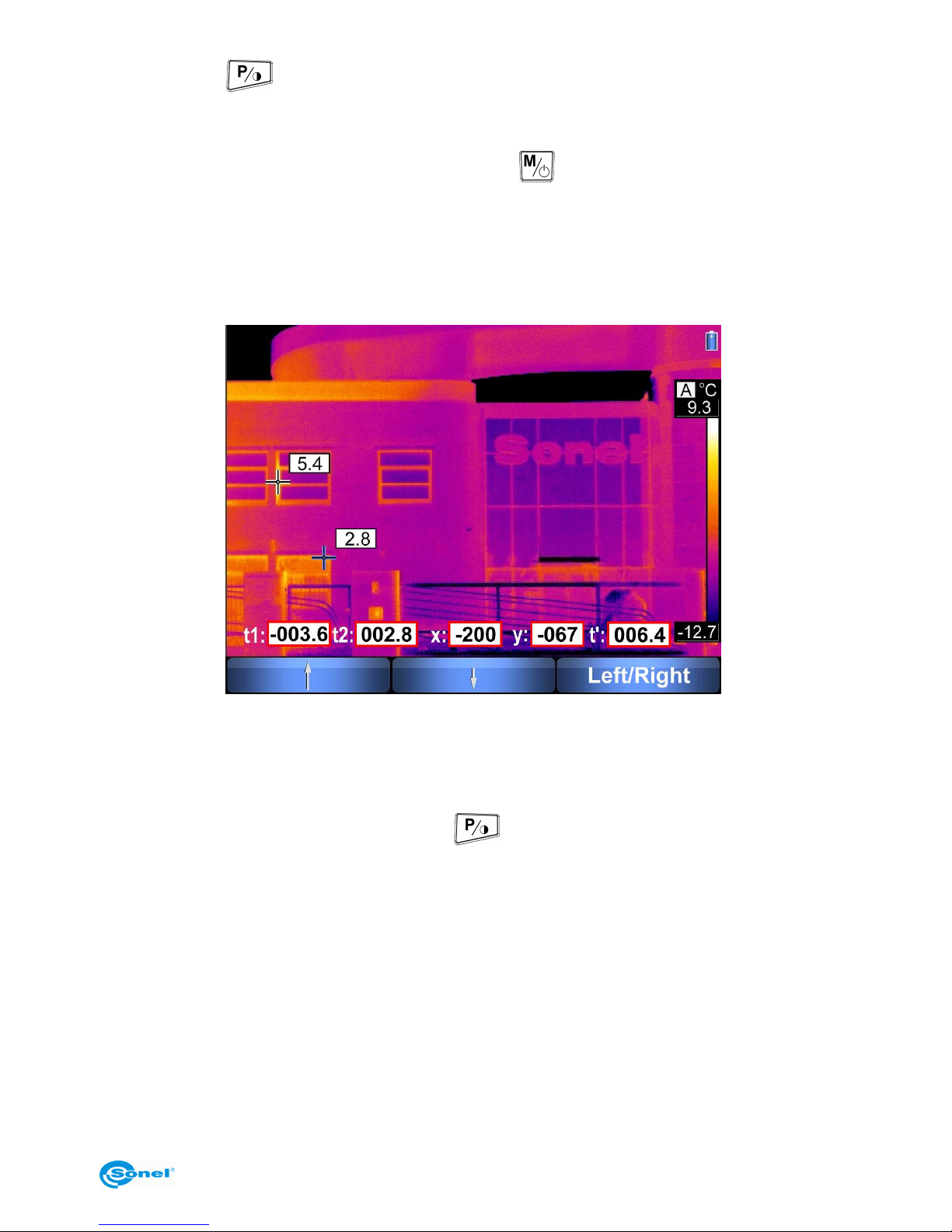
ing the button causes switching over to the "Left/Right" mode. Regardless of the
readout spot position, a pointer indicating maximal or minimal temperature is also continuously displayed on the screen.
In the ”Spot” mode after pressing simultaneously and trigger switch (10), the measured temperature (of the readout spot – center or moved; the coordinates are shown in
fields x and y) will be saved in field t1. If the location of the readout spot is changed, as
described above, or the camera is moved to other object, the next simultaneous press of
[] and trigger switch (10) will save the current temperature to field t2. The difference between t1 and t2 is displayed in field t’.
Pressing the trigger switch (10) causes leaving the "Spot" mode and the return of the
temperature readout spot to the centre of the screen.
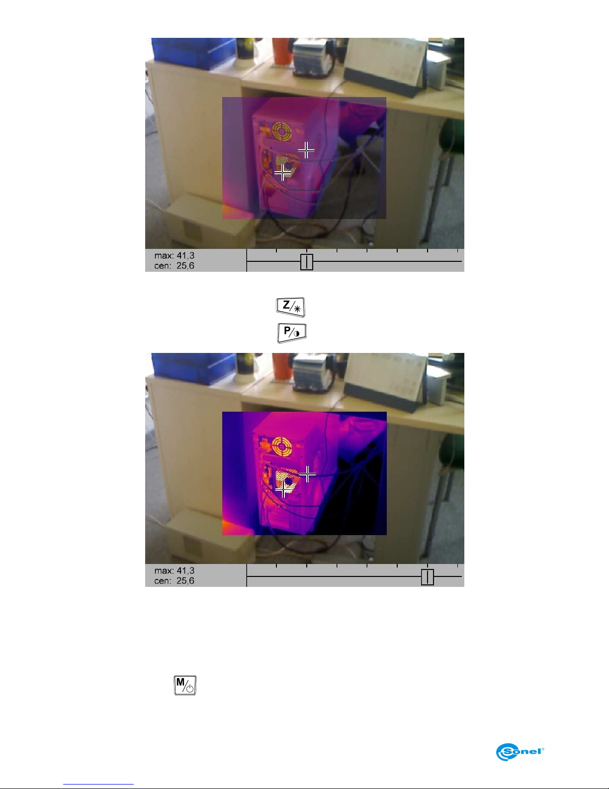
3. "Fusion" mode.
After selecting the "Fusion" mode (button ), the screen will display centrally located
thermal image fused with visible image:
Page 16
SONEL KT-384 THERMAL IMAGER
16
In the bottom part of the screen, a slider is displayed showing the value of image fusing
ratio - by sliding it to the left (button ) the thermal image intensity is decreased,
whereas by sliding it to the right (button ) the intensity is increased:
The place of maximal temperature (or minimal - depending on the chosen temperature
alarm mode - see section 3.11.2) is continuously marked as well as the central spot of the
examined area; the values of their respective temperatures are given in the bottom left
corner: "max" - maximal temperature (or "min" - minimal) as well as "cen" - central spot
temperature.
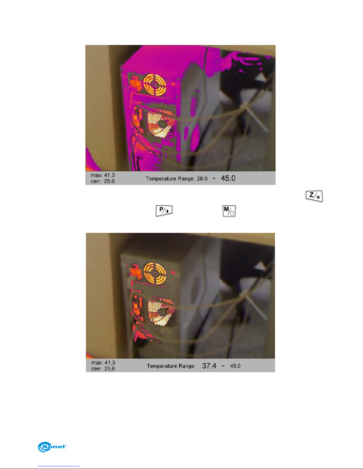
Pressing the button
causes switching over to a special mode of fused images, where
these images are displayed in full. Part of the image, with temperatures within the range
Page 17
OPERATING MANUAL
17
shown on the bottom bar, is displayed as thermal image, and the remaining part of the
image, with temperatures out of this range, is displayed as a visible image.
Adjustment of the temperature range limits is performed with buttons: pressing
causes increasing the temperature, decreasing it; toggles between adjusting
the minimal and maximal values of the range.
The temperature range can be selected freely between 0 and 400°C
Pressing the trigger switch (10) causes switching over to the infrared image mode.
NOTE:
- Using FUSION modes is recommended for distances longer than 1.5 m; in case of
shorter distances, the images are shifted vertically (parallax phenomenon).
Page 18
SONEL KT-384 THERMAL IMAGER
18
3.6 Manual calibration
During operation, the camera runs periodic auto-calibration (it is signalled with the symbol
appearing in the top left corner). Calibration can also be run manually at any time.
When no menu is displayed on the screen, press simultaneously (briefly) the button
and the trigger switch (10). Then calibration will be run and signalled just like the automatic one.
3.7 Laser pointer
The laser pointer can be turned on (when there is no menu invoked on the screen) after
pressing and holding the button (turning on occurs after approx. 1.5 sec.), and is
turned off after releasing the button or after pressing the trigger switch.
NOTE!
In case of direct contact, the laser beam can damage eyesight, therefore
DO NOT DIRECT EYESIGHT TOWARDS THE LASER BEAM,
or direct the beam towards persons or animals!
Take particular care, because the laser beam can reflect off shiny surfaces.
When the laser pointer is turned on, an additional message is displayed on the screen -
.
Due to safety reasons, the function is accessible, if the laser was previously activated in
the menu parameters settings (see section 3.11.6 - "Function settings").
3.8 LED flashlight
In order to facilitate operation of the instrument in dark spaces, the camera is equipped
with a LED flashlight. This function is invoked by simultaneous pressing the buttons
and
.
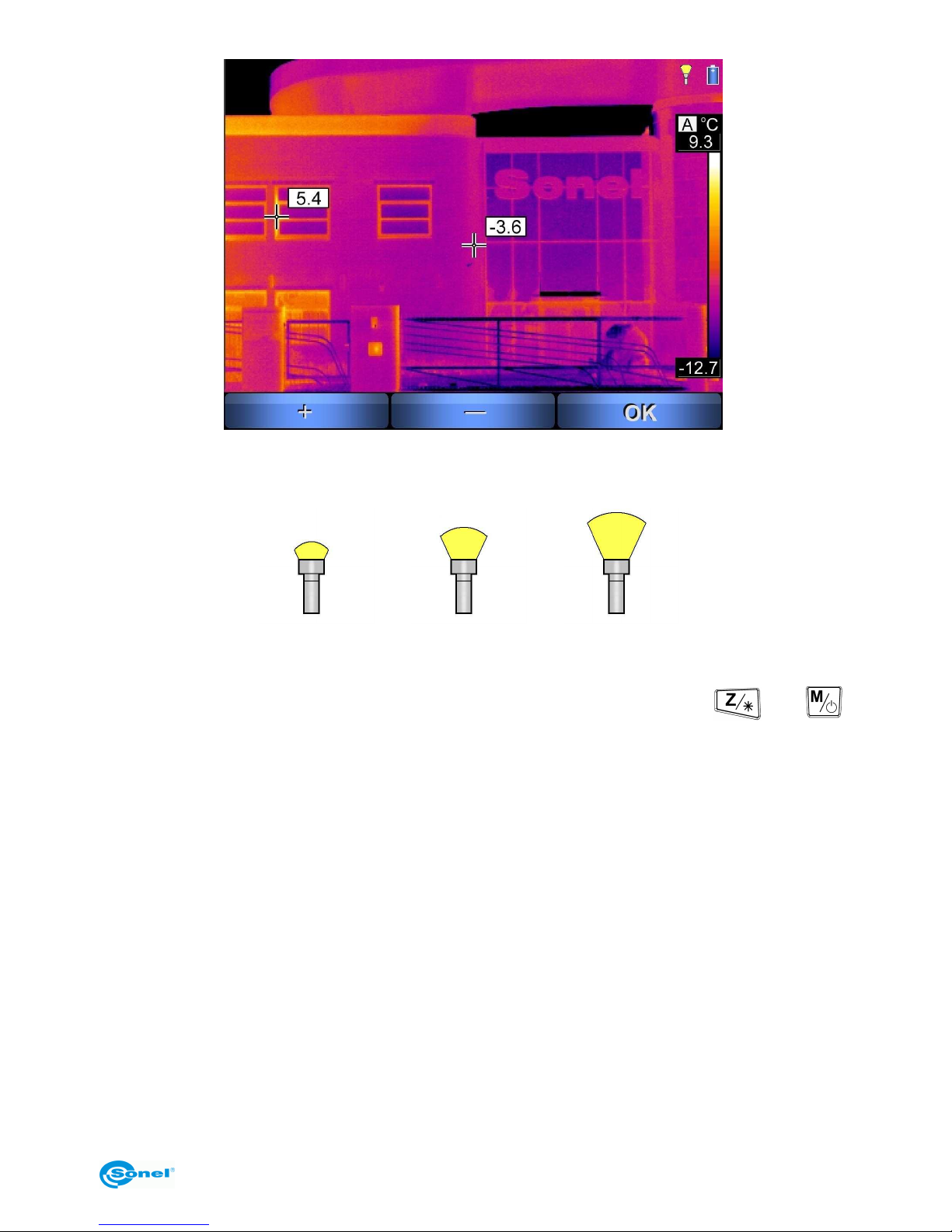
A function bar is displayed in the bottom part of the screen, where pressing "+"
(button ) causes turning the flashlight on and increasing its brightness (3 levels),
pressing "" (button ) causes decreasing its brightness until it is turned off; pressing
"OK" confirms flashlight brightness (or turning it off) and causes leaving this function. The
flashlight will be on with the set brightness until the function is invoked again or the camera is turned off.
Page 19
OPERATING MANUAL
19
Information of turned on flashlight is displayed symbolically in the top right corner of the
screen; shape of the symbol changes depending on the brightness level:
min.
max.
3.9 Dew point
The dew point value is displayed after simultaneous pressing of buttons and .
The information is calculated based on room temperature and humidity.
The dew point is an indication of moisture content in the air and defines the value of temperature at which the cooled down air becomes saturated with water vapour - thus it is the
temperature (in °C) at which water vapour turns to water under current working pressure.
When air temperature reaches dew point, condensation of water occurs on ground surface and objects as dew, hoarfrost, rime; also on walls of rooms, etc.
3.10 Capturing and saving image with a voice annotation
The camera displays image in continuous manner, refreshing it 50/60 times per second.
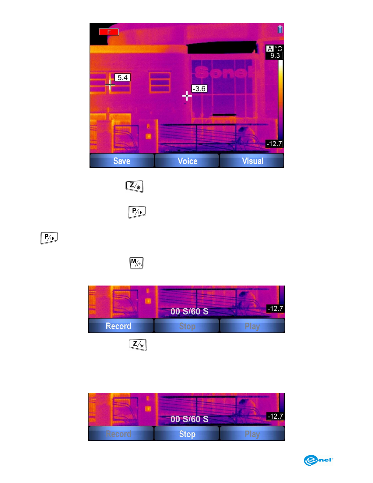
In order to capture the image at a given moment, press the trigger switch (10) - this will
freeze the image and display a screen menu:
Page 20
SONEL KT-384 THERMAL IMAGER
20
- Pressing "Save" (button ) causes saving the captured image (without a voice note)
and switching over back to the real time display mode.
- Pressing "Visual" (button ) switches the screen to visible image mode (a still visible
image corresponding to the captured thermal image is displayed), pressing the button
again or the trigger switch (10) switches the screen back to the captured thermal
image.
- Pressing "Voice" (button ) causes switching to a voice annotation recording mode
(max. 1 minute):
Selecting "Record" (button ) starts recording of a voice annotation. During recording,
the current length (in seconds) of the recording is displayed over the command bar.
The user can interrupt the process at any time by pressing the trigger switch (10); this
causes returning to the "Save - Voice - Visual" menu without recording any voice annotation.
Page 21
OPERATING MANUAL
21
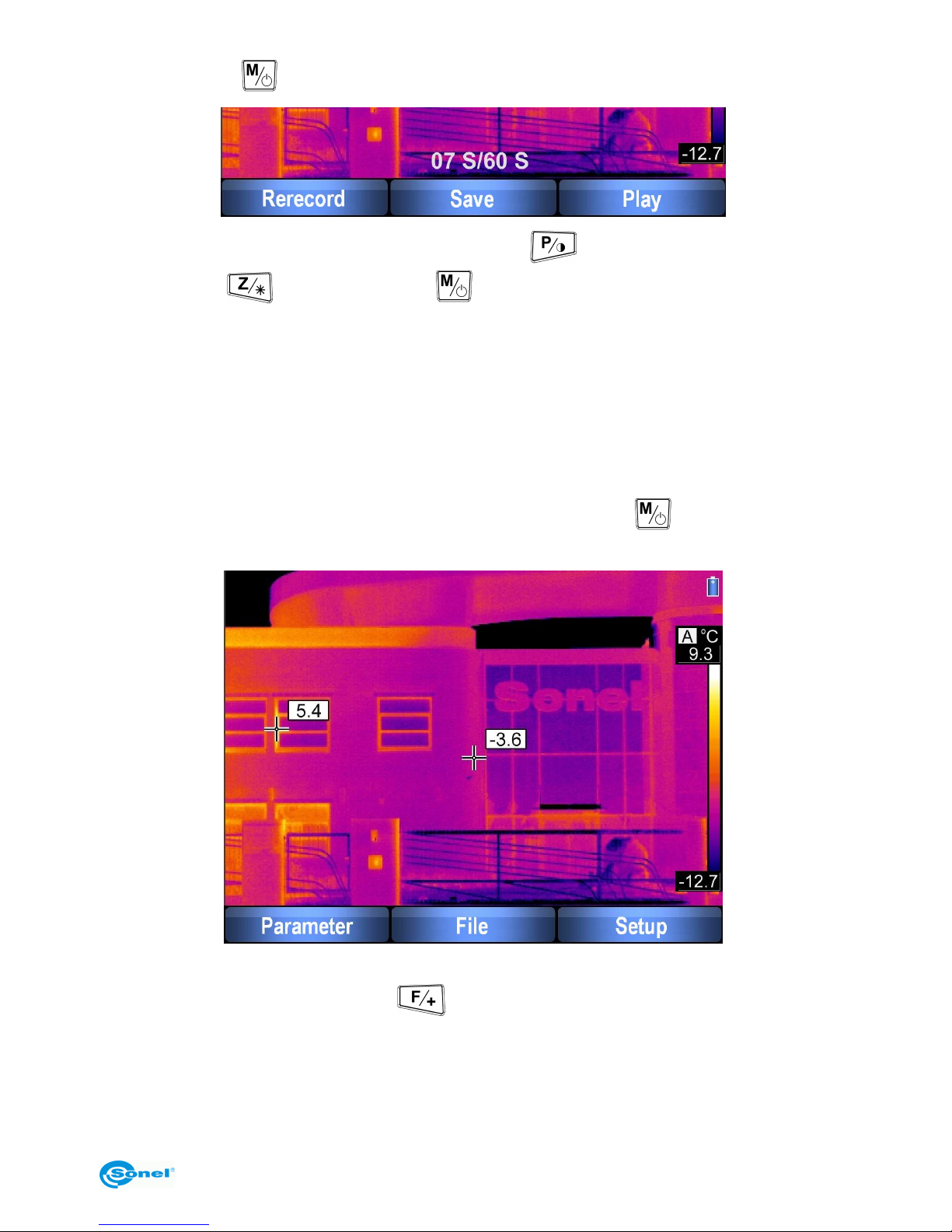
Pressing "Stop" ( ) or reaching 60 s ends recording of an annotation.
The recording can be played back ("Play" - button ) through the speaker (5), or repeated (button ). Pressing "Save" ( ) saves the captured image with the recorded
voice annotation.
NOTES:
- A voice annotation can be added only BEFORE the image is finally saved.
- Pressing the trigger switch (10) causes returning to the real time thermal image mode
without saving the captured image.
3.11 Function settings
When no menu is displayed on the screen, pressing the button causes the following
options to be displayed:
The function settings menu can be left at any time by pressing the trigger switch (10).
After selecting "Parameter" (button ), a sub-menu is opened allowing for setting pa-
rameters of the camera:
Page 22
SONEL KT-384 THERMAL IMAGER
22
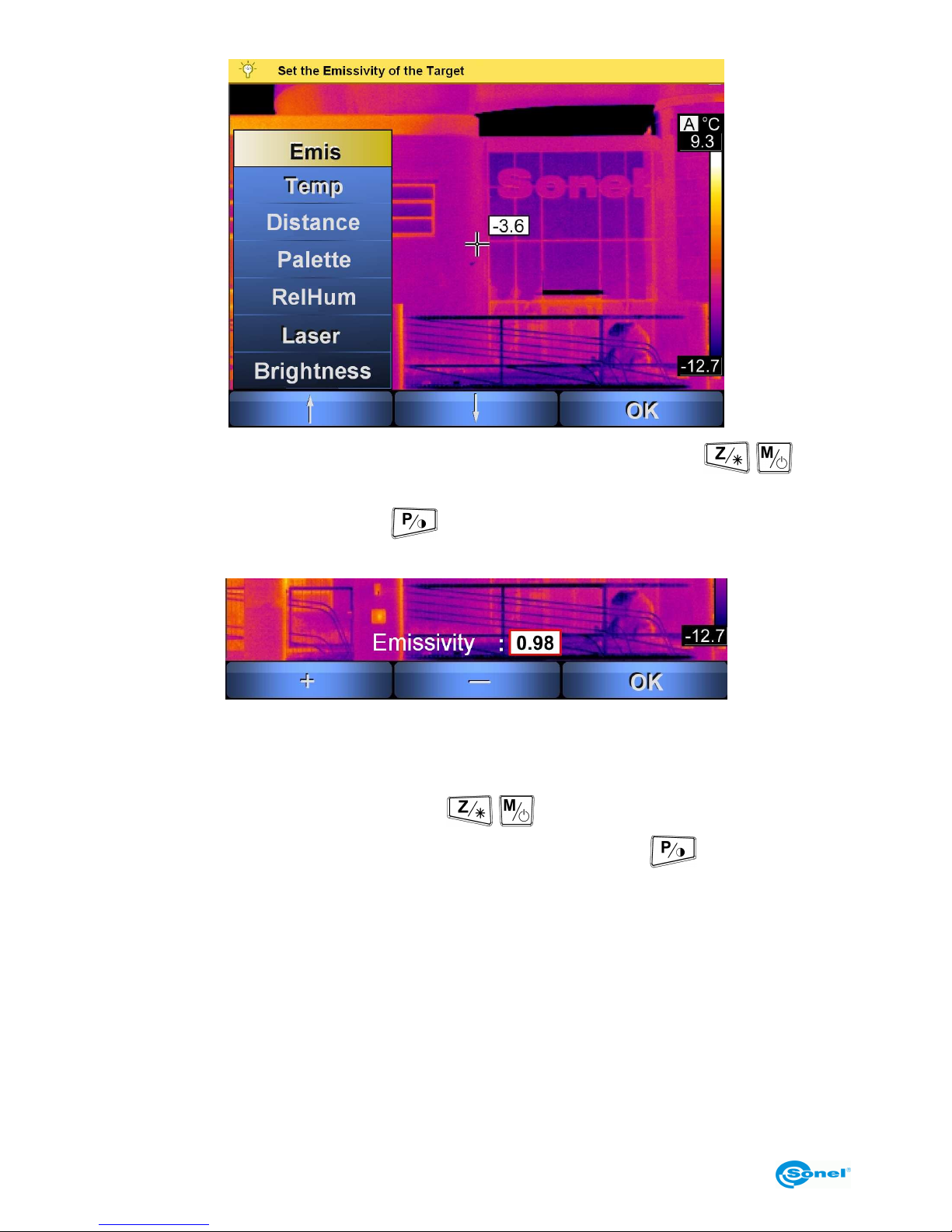
Select the desired parameter using the "up"/"down" arrows (buttons / ); after
highlighting the parameter, its full designation is displayed on the top bar of the screen.
After confirming with "OK" (button ), a sub-menu is opened allowing for adjustment
of the selected parameter:
3.11.1 Object emissivity settings
Selecting "Emis" and confirming with "OK" causes entering the sub-menu "Set the Emissivity of the Target". By pressing "+"/"-" ( / ) the emissivity coefficient can be decreased/increased within the range of 0.01...1.00. Pressing "OK" ( ) confirms the new
value.
Default value is 0.98.
Example values of the emissivity coefficient are presented in chapter 8.
3.11.2 Ambient temperature and temperature alarm settings
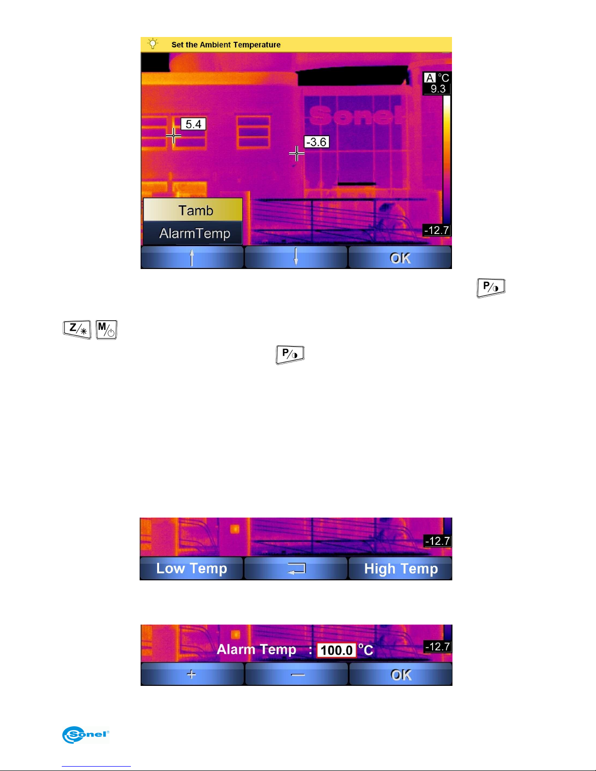
Selecting "Temp" and confirming it with "OK" allows for adjusting the values of ambient
temperature or alarm temperature settings.
Page 23
OPERATING MANUAL
23
After selecting "Tamb" (Set the Ambient Temperature) - by pressing “Setup” ( ) the
camera is switched over to manual mode, where the buttons "+" or "-" (buttons
/ ) allow for increasing/decreasing the value of ambient temperature within the
range of -40.0...+85.0°C. Pressing "OK" ( ) confirms the new value.
The function allows for setting proper relation between ambient temperature and the temperature of the examined object; it is useful when measurements are carried from a distance, e.g. from a space where temperature differs from ambient temperature of the examined object. No adjustment is required for the majority of measurements.
Another activation of the function, and then its deactivation by pressing the trigger switch
(10), causes switching over to automatic mode.
Selecting "Alarm Temp" sub-menu allows for choosing sound alarm for high temperature
(after exceeding the specified value) or low temperature (after going below the specified
temperature):
After selecting "Low Temp" or "High Temp", the required value is set by pressing "+" or "-"
and then confirmed with "OK".
Page 24
SONEL KT-384 THERMAL IMAGER
24
NOTES:
- Depending on the selected type of an alarm, the cursor on the screen will mark the point
of either the highest or the lowest temperature value (see section 2.2)
- By default, the high alarm is set to 100°C, and t he cursor indicates the point of the highest temperature.
3.11.3 Selecting distance from an object
Selecting "Distance" and confirming it with "OK" causes entering the sub-menu "Set the
Distance between Camera and Target". By pressing "+"/"-" (buttons / ), the dis-
tance between the camera and the examined object can be set within the range of 0.1...30
metres. Confirm changes with "OK" ( ).
Adjusting the distance allows for correction of the influence of medium (pollutions, fog,
smoke, gases) the infrared radiation passes through onto the accuracy of measurement.
Default value is 1.8 m.
3.11.4 Selecting colour palette
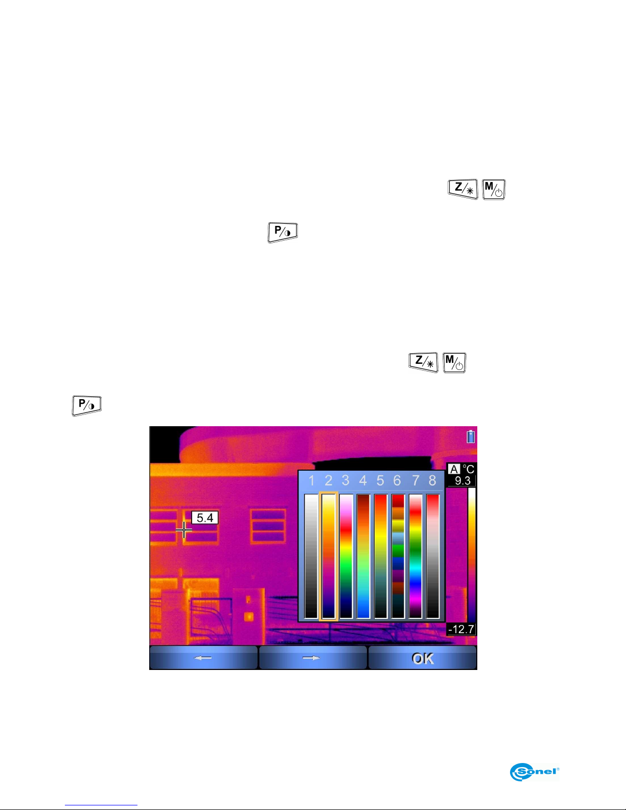
Selecting "Palette" and confirming it with "OK" causes entering the sub-menu "Select One
Palette from Eight Palettes". By pressing "←" or "→" (buttons / ) a colour palette
can be selected for the desired mapping of temperatures. Confirm changes with "OK"
( ):
Page 25
OPERATING MANUAL
25
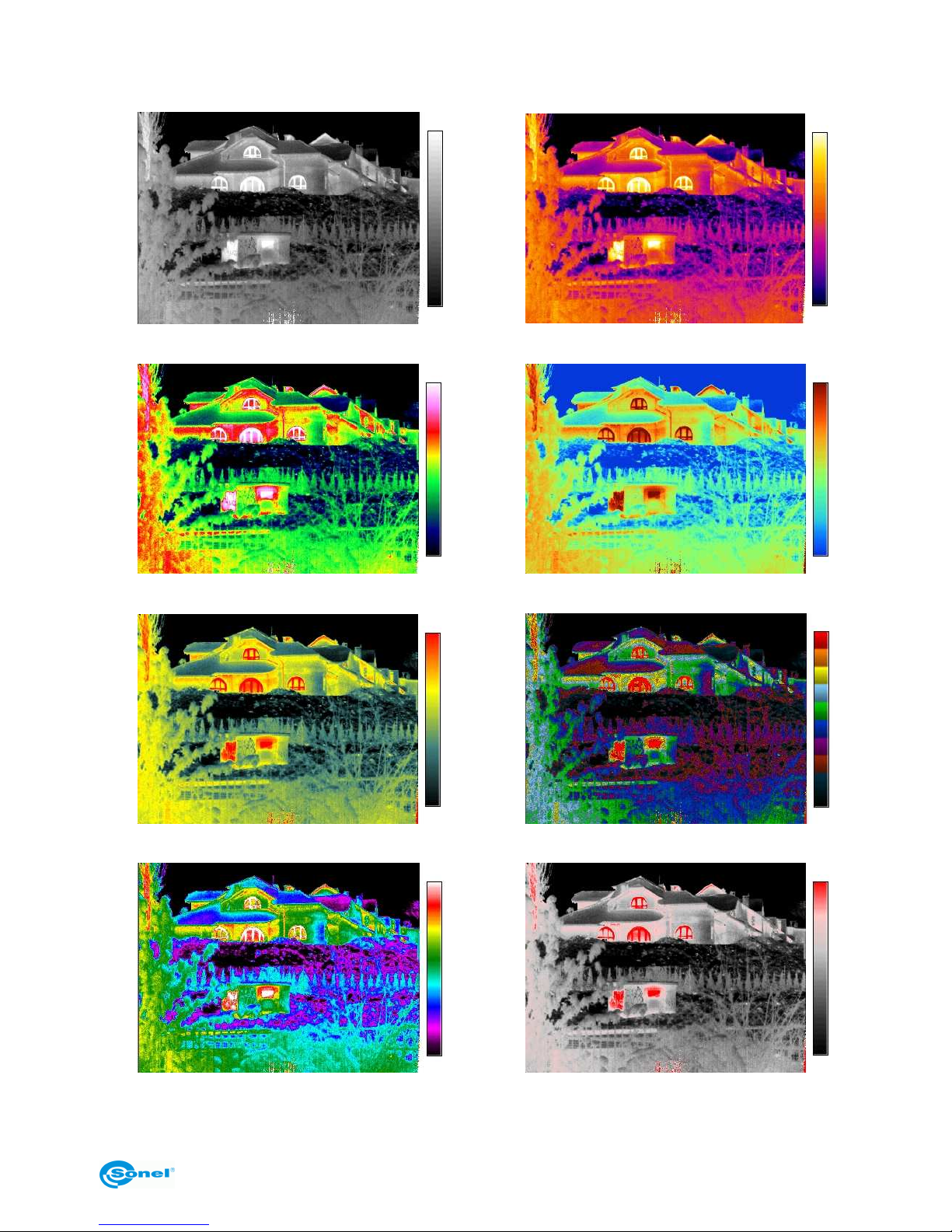
Available colour palettes:
1
2
3
4
5
6
7
8
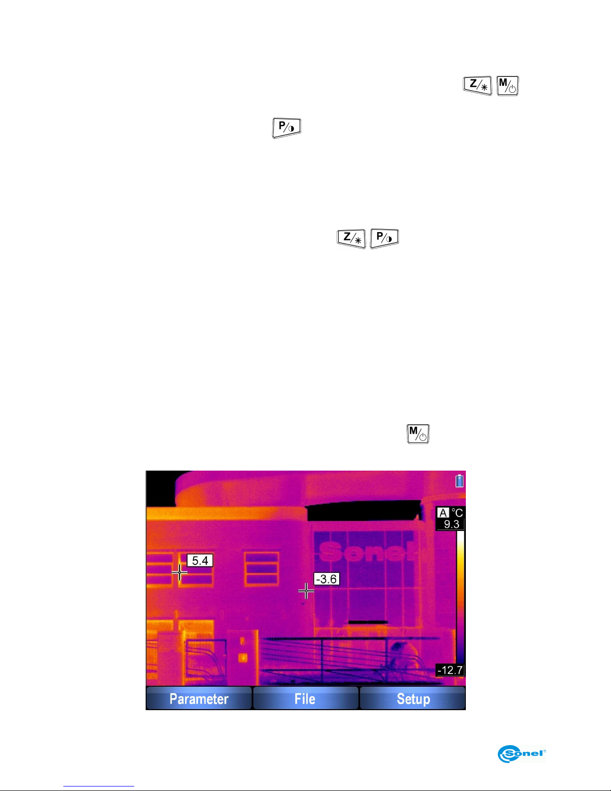
By default, colour palette no. 2 is selected.
Page 26
SONEL KT-384 THERMAL IMAGER
26
3.11.5 Setting relative humidity
Selecting "RelHum" and confirming it with "OK" causes entering the sub-menu "Set the
Relative Humidity of the Environment". By pressing "+" or "-" (buttons / ) the
value of relative humidity can be set, depending on ambient condition, within the range of
0...100%. Confirm changes with "OK" ( ).
Default value is 70%.
3.11.6 Activation of laser pointer
Option "Laser" allows the user to enable or disable turning on the laser pointer - targeting
device. After entering the sub-menu "Enable or Disable the Laser Pointer", enable or dis-
able the laser pointer function using the buttons /
(current state is displayed
above the menu bar). Additionally, in the top left corner of the screen, information about
the laser pointer readiness status will be displayed for 2 seconds after making the selection.
By default the laser is disabled.
3.11.7 Brightness
This option allows for selecting one of 3 brightness levels of the screen. Select "+" to increase, "-" to decrease, and "OK" to confirm the selected level of brightness.
3.12 Camera settings
When no menu is displayed on the screen, pressing the button causes the "Parameter - File - Setup" options to be displayed.
Page 27
OPERATING MANUAL
27
The settings menu can be left at any time without any changes by pressing the trigger
switch (10).
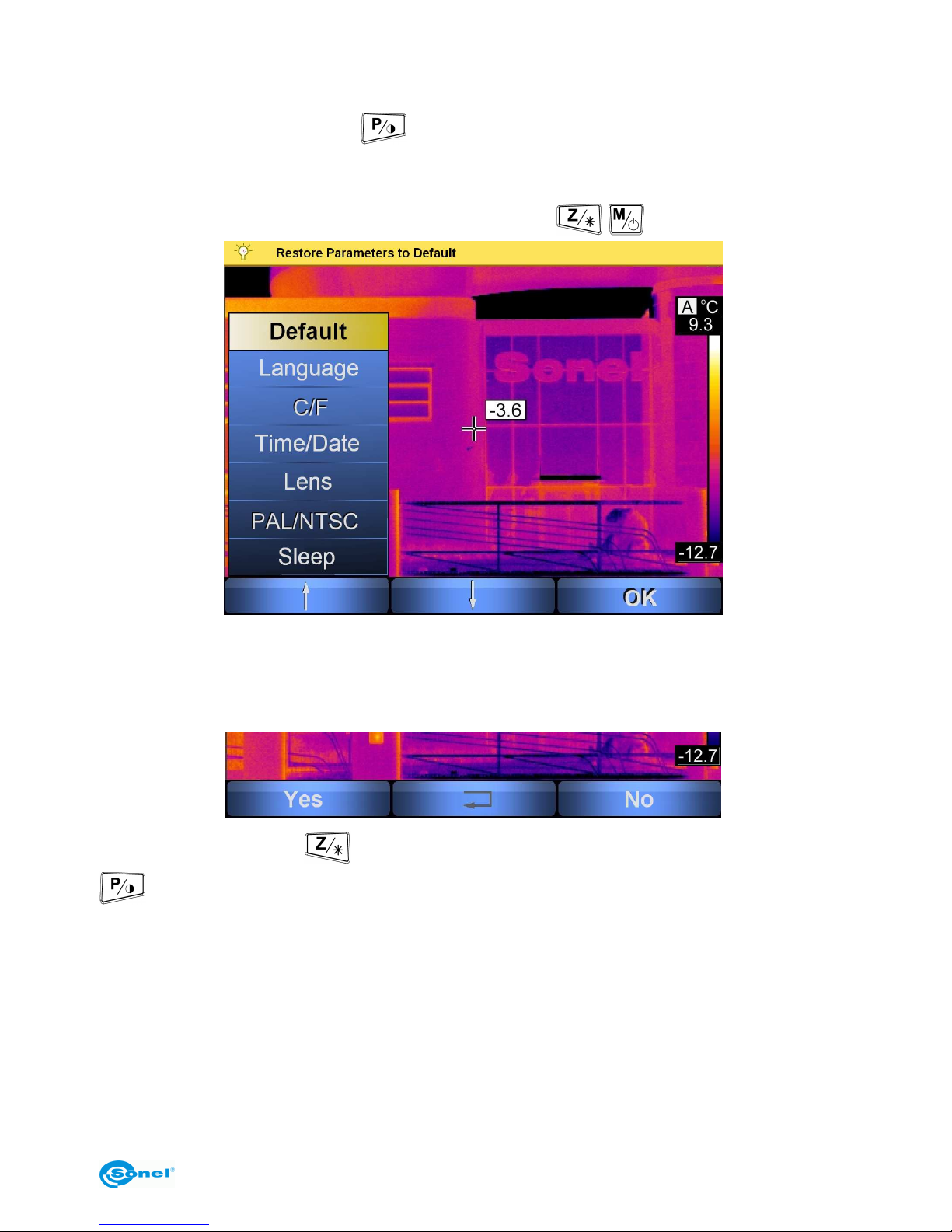
After selecting "Setup" (button ) a sub-menu is opened allowing for setting own parameters of the camera (language, temperature units, time/date, type of lens, type of output video signal, temperature alarm thresholds) or restoring default values of settings. An
option is selected with the "up"/"down" arrows (buttons / ):
3.12.1 Restoring default settings
Selecting "Default" and confirming it with "OK" causes entering the sub-menu "Restore
Parameters to Default".
Selecting "Yes" (button ) confirms restoring factory settings, whereas "No" (button
) or pressing the trigger switch (10) causes leaving the sub-menu without any
changes.
The following parameters are restored after choosing to restore default values:
- emissivity coefficient: 0.98;
- distance to the object: 1.8 m;
- colour palette: 2;
- relative humidity: 70%;
- laser pointer: disabled;
- alarm temperature value: 100°C (212°F);
- lens: standard (25 mm);
Page 28
SONEL KT-384 THERMAL IMAGER
28
- screen brightness - medium;
- hibernation - disabled;
3.12.2 Selecting the user interface language
Selecting "Lang" and confirming it with "OK" causes entering the sub-menu "Select the
Language of the User Interface". The user can select the Polish, English, Spanish or Rus-
sian language. Selection is made with arrows (buttons / ), and requires confirming it with "OK" (button ).
3.12.3 Selecting the units of temperature
Selecting "C/F" and confirming it with "OK" causes entering the sub-menu "Select the Unit
of the Temperature", where the user can choose between "C" (button ) - degrees
Celsius, or "F" (button ) - degrees Fahrenheit.
Pressing the button or the trigger switch (10) causes leaving without any changes.
3.12.4 Setting time and date
Selecting "Time/Date" and confirming it with "OK" causes entering the sub-menu "Setup
Time and Date" allowing for setting internal clock of the camera. Files will be saved with
date and time stamp according to this clock.
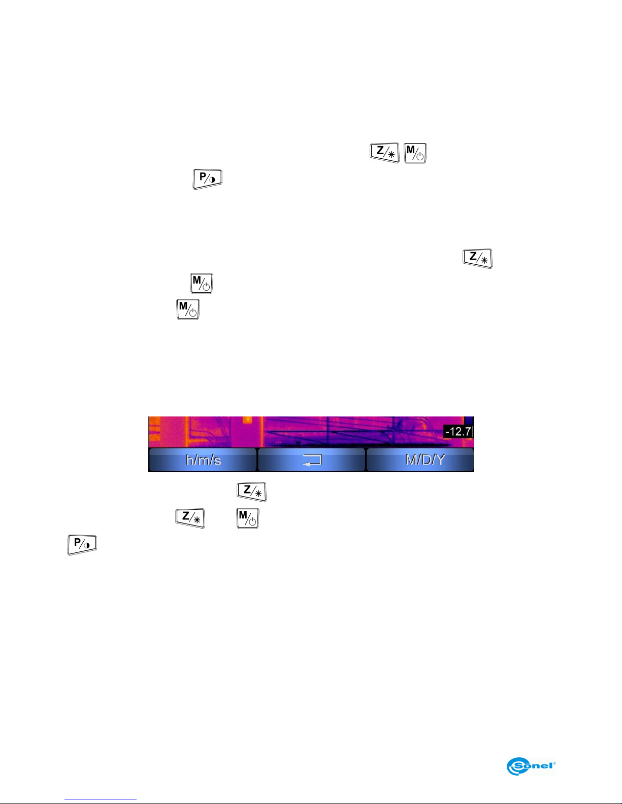
After selecting "h/m/s" (button ), the clock setting sub-menu is presented: Pressing
„+” or „” (buttons and ) allows for setting hours, the "Minute" option (button
) allows for setting minutes in similar manner, or for setting seconds. The new clock
setting (displayed during setting over the menu bar) can be saved with "OK", or this submenu can be left by pressing the trigger clock (10).
Similarly, after entering the date sub-menu ("M/D/Y"), year can be set („+” and „”), following by month and day. Save the settings or leave the menu without saving by pressing the
trigger switch (10).
NOTE: Date is displayed in the month/day/year format.
3.12.5 Selecting lens
The "Lens" option allows for setting the type if installed lens - choose between standard
25 mm lens (21.7°x16.4°) or optional 42 mm lens 13. 04°x9.8°), wide-angle 13 mm lens
(40.53°x30.96°), or telephoto 70 mm lens (7.85°x5.8 9°).
Page 29
OPERATING MANUAL
29
If the 1-lens version of the camera was purchased, this option may be inactive.
3.12.6 External display monitor and selecting the type of video signal
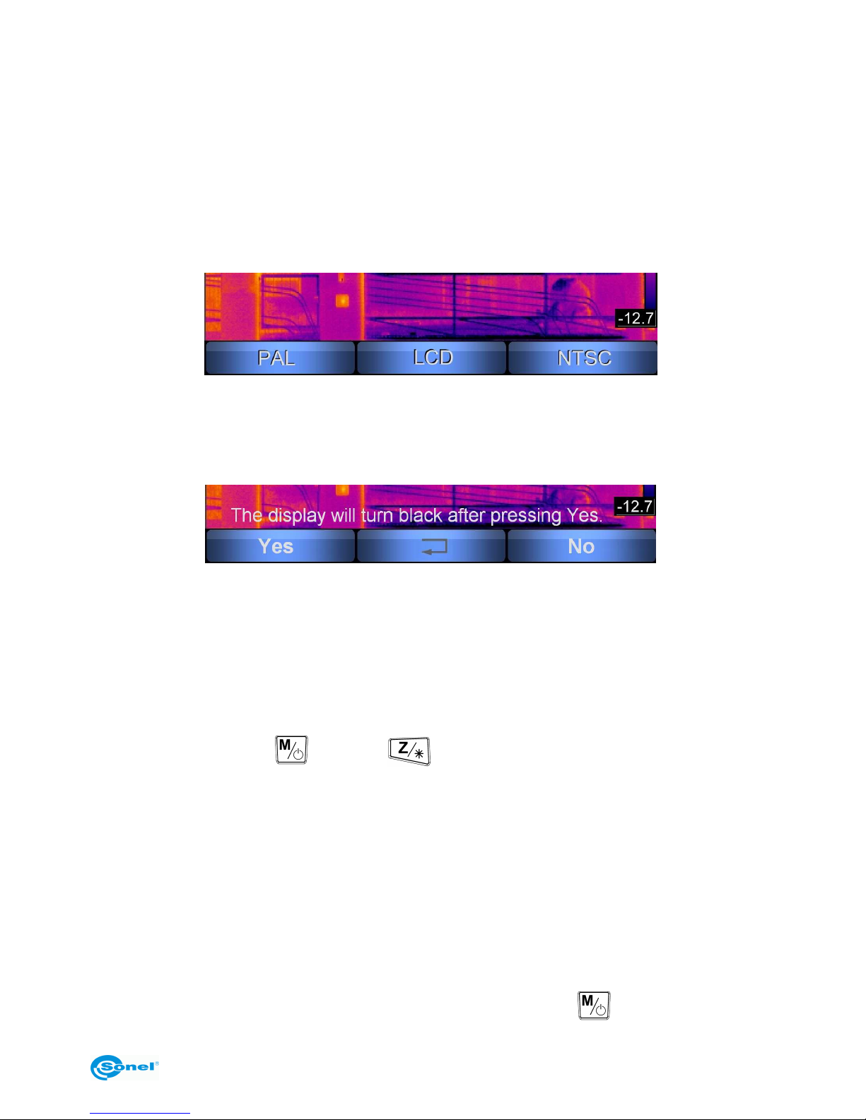
Selecting the "PAL/NTSC" option allows for redirecting display from the built-in LCD display to an external display monitor as well as selecting the type of video signal (PAL or
NTSC).
The external display monitor should be connected to the camera socket (12) over the
supplied cable.
After selecting this option:
Additional confirmation or rejection - "Yes" or "No" is required, because in case of selecting "PAL" or "NTSC" the image is no longer displayed on the built-in display, but on the
connected external monitor only (including menu bars - descriptions of button functions).
Therefore, in case of selecting "PAL" or "NTSC", an additional warning is displayed:
After confirming the selection the camera is switched to the external display monitor
("PAL" or "NTSC") or to the built-in display ("LCD"). Selecting "No" causes returning to the
selection screen, whereas pressing the trigger button (10) causes leaving the menu without changes.
After making the selection and confirming it, the camera is still in the "PAL/LCD/NTSC"
selection mode - to leave it, press the trigger switch. Until then, if an external display
monitor has been selected and there are problems with displaying image from the cam-
era, pressing the button , and then restores operation of the built-in display.
NOTE: Before connecting / disconnecting the camera it is recommended to turn it off.
3.12.7 Auto-off function (hibernation)
This allows for defining the amount of idle time elapsing before the camera turns off the
display and enters hibernation state. Selecting "Enabled" allows for defining the time (5,
10, 30 minutes); "0" causes entering hibernation state instantly. "Disabled" inactivates this
function.
3.13 Files - viewing, settings, information, video mode
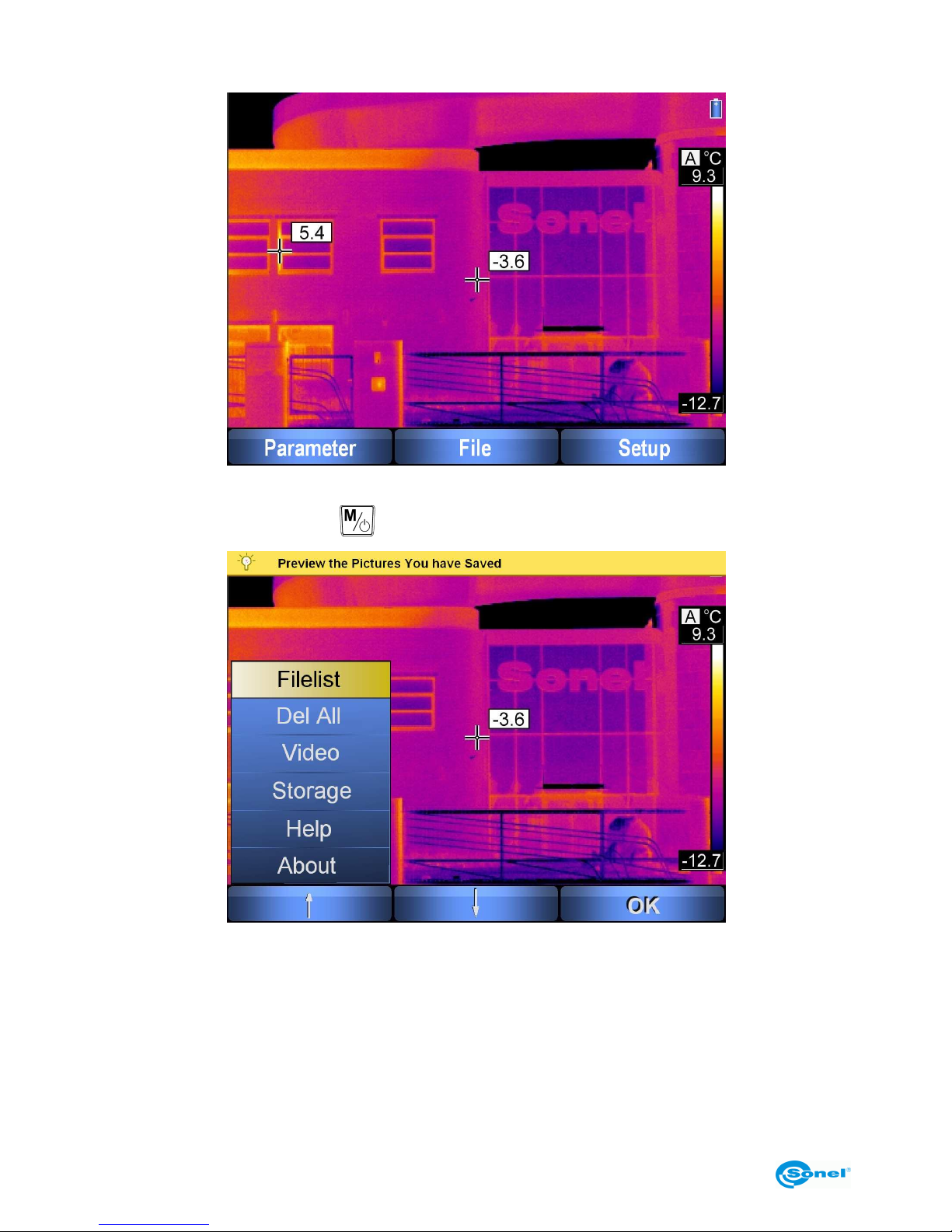
When no menu is displayed on the screen, pressing the button causes the following
Page 30
SONEL KT-384 THERMAL IMAGER
30
options to be displayed:
The settings menu can be left at any time by pressing the trigger switch (10).
After selecting "File" (button ), the following sub-menu is opened:
3.13.1 Viewing saved images or video files and removal of single files from
memory
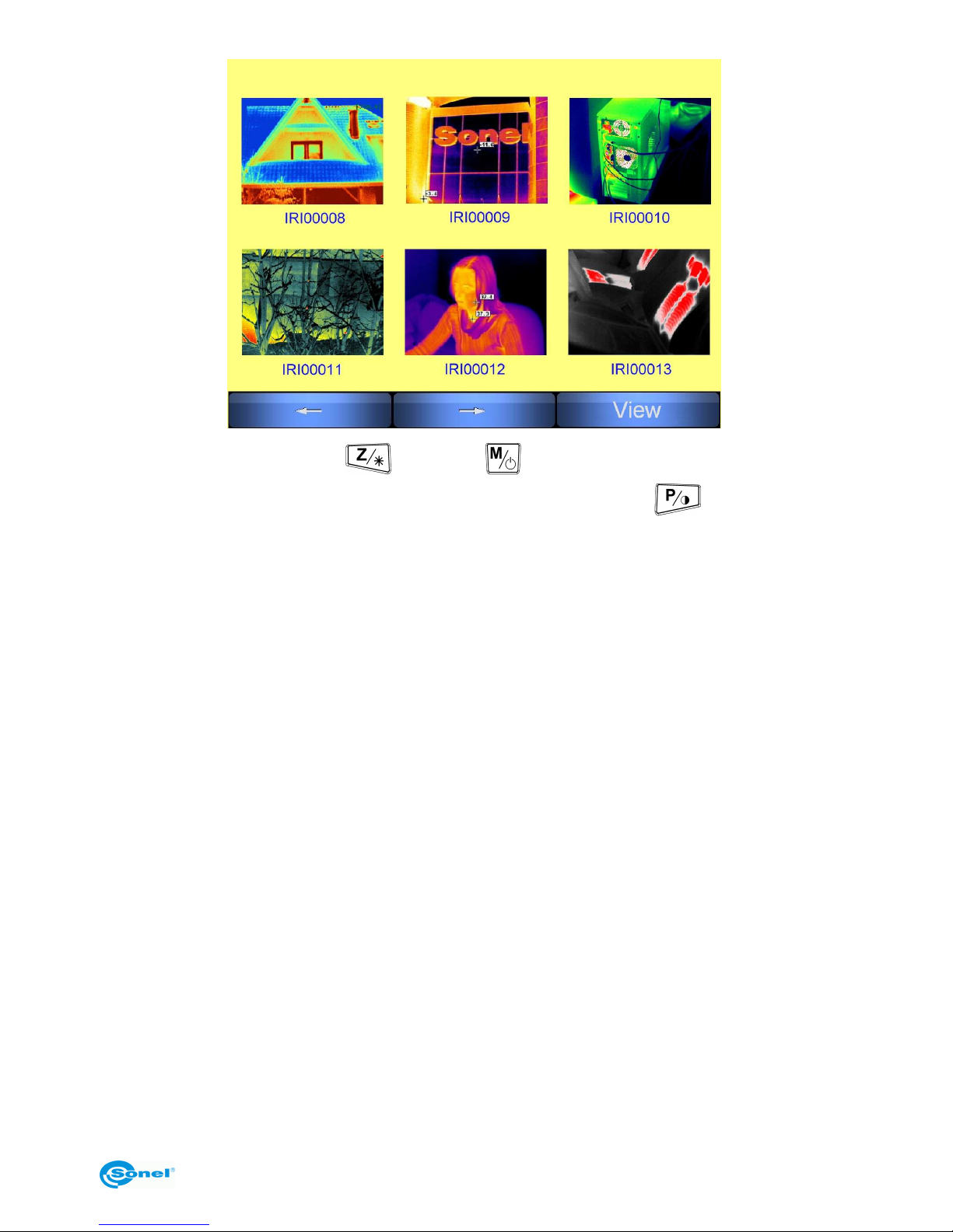
Selection of "Files", and then "Images" causes displaying a preview of images recorded in
memory defined as default (selected folder on the SD memory card or the built-in memory, see section 3.13.4):
Page 31
OPERATING MANUAL
31
Select file using arrows "←" ( ) and "→" ( ). When a given image is highlighted, it
can be displayed in full screen mode by pressing "View" (button ); 3 more options
are then available. Selecting "Delete" allows for removal of selected image file (after confirming it with "Yes"; pressing "No" cancels the command and restores image view); besides that, the visible image, saved with the thermal image, can also be previewed ("Visual"), and the voice annotation ("Voice") can be played, if only was recorded. Pressing the
trigger switch (10) causes returning to the preview mode and selecting saved images.
Selecting "Files" followed by "Video" allows for viewing or deleting thermal video files recorded on the SD memory card. This function is active, given the SD card is selected for
storage.
3.13.2 Deleting all saved images
After selecting the "Del All", option choose between "Del all Image" and "Del all Video".
Depending on the selection, the "Delete All the Images?" (or "... the Videos") question will
be displayed on a bar in the top part of the screen. Selecting "Yes" confirms and removes
all images saved in the built-in memory or the current folder on the SD memory card (depending on the selected storage, see section 3.13.4), or all video files on the card. Selecting "No" causes returning to the "File" menu.
3.13.3 Video
Detailed description of the infrared video recording function can be found in chapter 5.
3.13.4 Selecting storage medium
The "Storage" option allows for choosing, whether images will be saved to the built-in
Uflash memory, or to the removable SD memory card.
Page 32
SONEL KT-384 THERMAL IMAGER
32
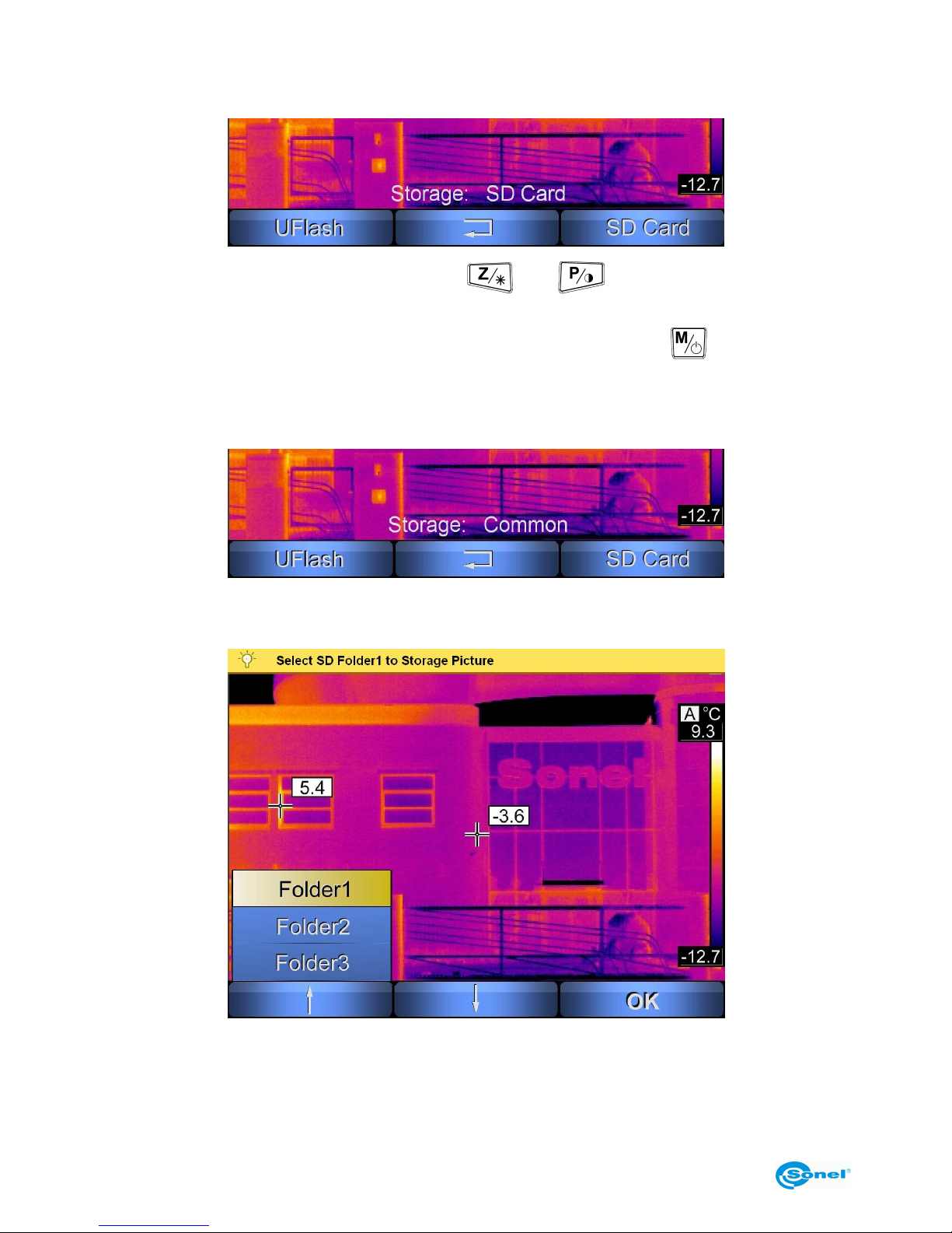
After selecting the "Storage" command, current state is displayed above the menu bar Uflash (saving and all operations in the built-in memory) or "SC Card":
To select working storage use the buttons and corresponding to "Uflash" or
"SD Card". Selecting "SD Card", when no card is present in the SD card slot (14) of the
camera, causes displaying the "No SD Card" message. Pressing
or trigger switch
(10) causes leaving menu without any changes.
After selecting "SD Card", if installed in the camera, select the "Common" (to save all files
in 1 folder) or "Folder" mode:
After selecting the "Folder" mode, a folder on the SD card can be selected for saving
thermal images:
NOTES:
- After placing an SD card in the slot (14), the camera automatically switches storage over
to the SD card in the last saved mode ("Common", "Folder1", "Folder2" or "Folder3").
- The camera is capable of using SD memory cards of size not exceeding 8 GB.
Page 33
OPERATING MANUAL
33
- Size of the built-in Uflash memory is 150 MB, and it allows for saving up to 100 images.
- Selecting "Folder1", "Folder2", ... corresponds to a respective folder on the SD card
named as "PICTURE1", "PICTURE2", ... In the "Common" mode, files are saved in the
"PICTURE" folder.
- In case of recording to the SD card, video files are saved in the "VIDEO" folder.
- The SD card must be formatted with the FAT32 file system.
3.13.5 Help
Selecting the "Help" option activates a quick guide displayed on the screen, including basic information related to operating the camera.
3.13.6 Information about hardware and software versions
Selecting the "About" option causes displaying the information about the versions of
hardware and software of the camera on the bar in the top part of the screen.
3.14 Power supply, charging batteries
The camera is powered by 6 alkaline, AA type batteries or rechargeable batteries, and
may also be powered from an AC power supply adapter.
The rechargeable batteries are charged without removing them from the instrument.
In order to start charging, plug the power supply to the socket (13) of the camera. The batteries are charged when the camera is turned off.
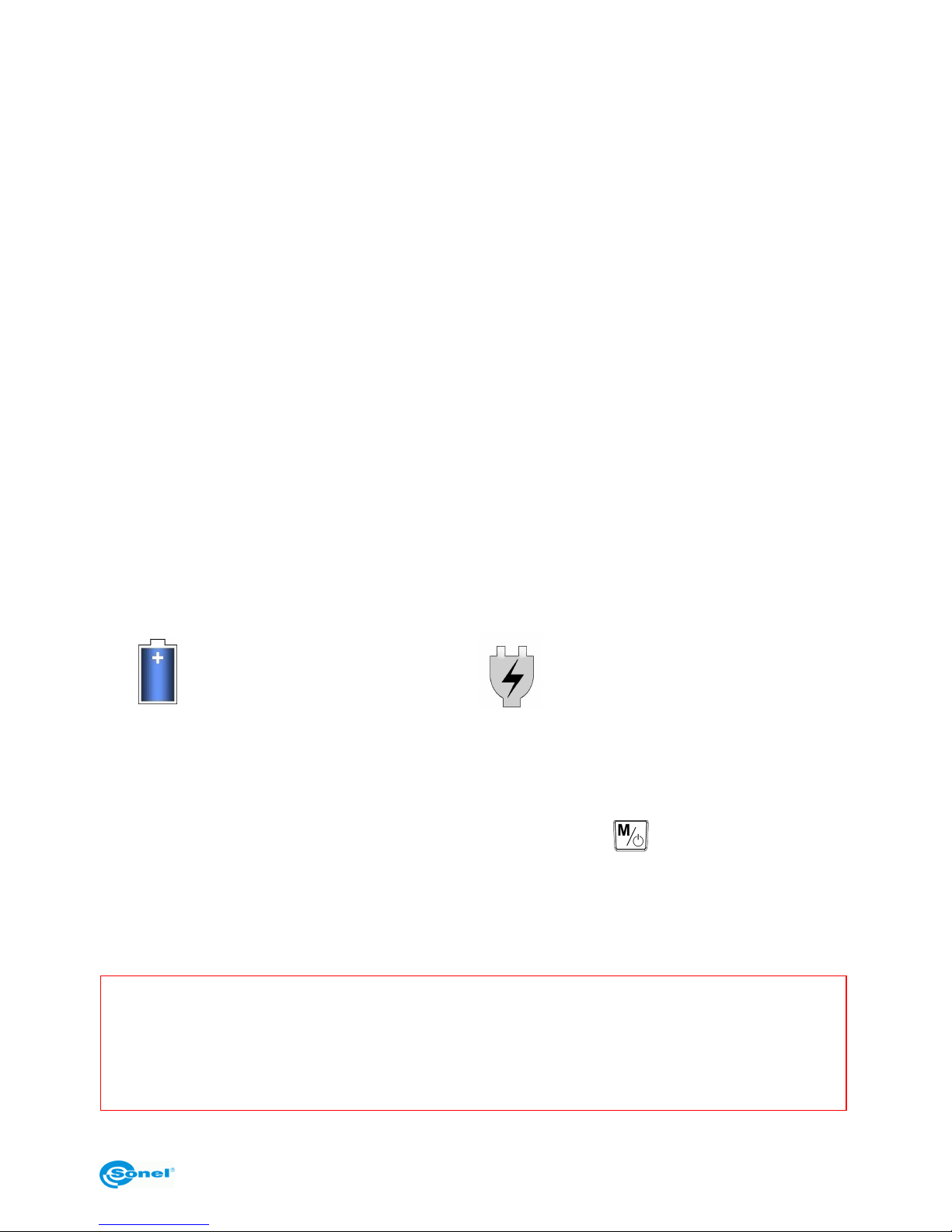
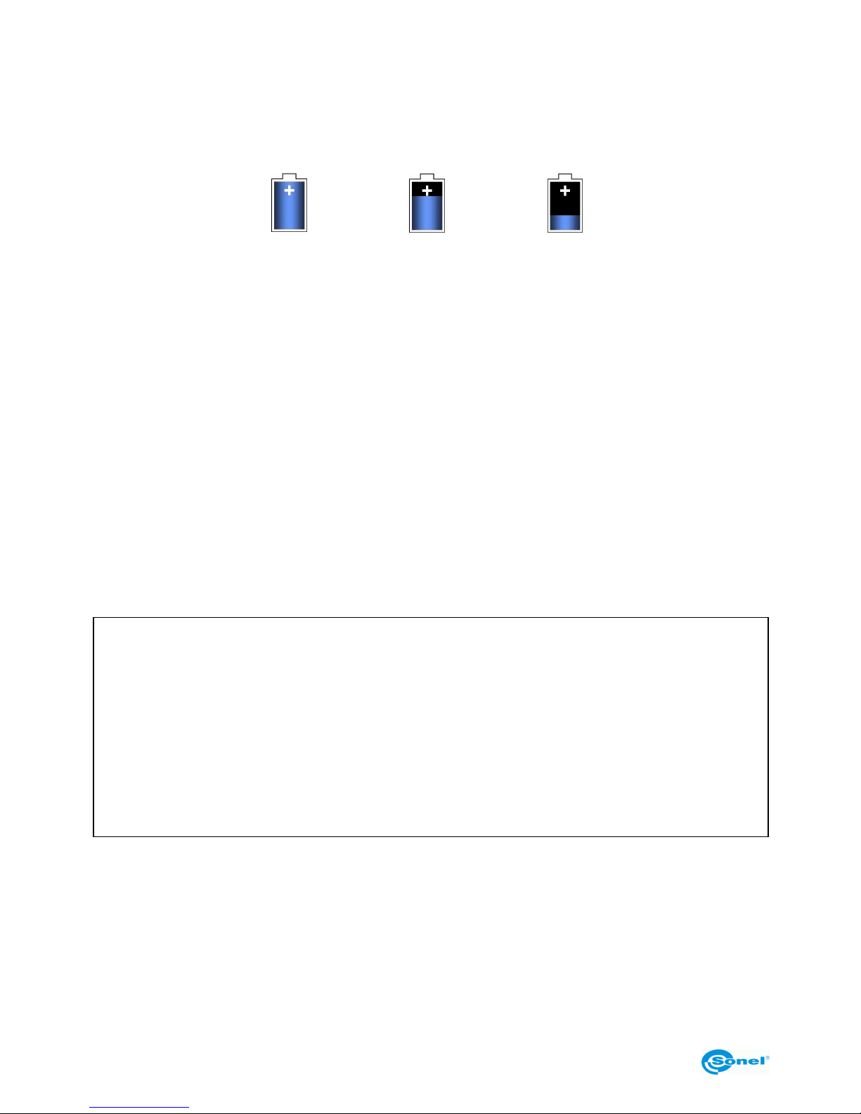
When the camera is turned on, a power status indicator is displayed in its top right corner:
- operation on battery power,
- operation on AC power supply.
3.14.1 Using the AC power supply adapter
Connection the AC power supply adapter is signalled by the indicator light (2). When the
camera is turned off, this indicator light signals charging state of rechargeable batteries.
After turning the camera on (pressing and holding the button for 2 seconds) the indicator light flashes (green/red) 3 times per second, and then (during self-test) switches to
solid red light.
After turning the camera off, if the AC power supply adapter is still connected, the indicator light signals charging the batteries.
NOTE!
Do not connect the AC power supply adapter, if regular batteries are installed in
the camera (non-rechargeable). Connecting the AC power supply adapter can lead
to explosion of batteries and destruction of the camera.
Page 34
SONEL KT-384 THERMAL IMAGER
34
3.14.2 Operation on regular/rechargeable batteries
After turning on the camera on battery power, the indicator light flashes alternating
green/red for a few seconds. During operation, the indicator light is turned off.
During operation of the camera, the charge level of rechargeable batteries is presented in
real time in the top right corner of the screen:
max.
min.
3.14.3 Charging rechargeable batteries
When the camera is turned off, and rechargeable batteries are installed, connecting the
AC power supply adapter and starting charging process is signalled by slower (approx. 1
per second) flashing on the indicator light (2). When the rechargeable batteries are
charged, the indicator light switches to solid green.
Quick flashing during charging indicates an abnormality (e.g. reversed polarity or damage
of rechargeable batteries) - in such case the charging process must be terminated immediately, and the cause of the abnormality must be checked.
In the case, where the signalled abnormality is due to high temperature of the rechargeable batteries, the charging process must be interrupted until the batteries cool down.
The Ni-MH rechargeable batteries do not require a full charge-discharge cycle during operation, however it is recommended to charge them fully during the first 3 charging sessions.
Rechargeable batteries must be replace all at once - do not use new and used ones or
mixed types together.
NOTE!
- Use only the AC power supply adapter supplied with the camera.
- Pay attention to polarity of batteries (regular or rechargeable)
while installing them in the camera.
- Rechargeable batteries must be charged in temperature 0...40°C.
- Do not remove rechargeable batteries from the camera while they are being
charged.
- To maintain required parameters of rechargeable batteries, unused rechargeable
batteries should be charged every 3 months.
3.14.4 General rules of using the Ni-MH rechargeable batteries
In case the instrument is not used for a prolonged time, it is necessary to remove the rechargeable batteries and store them separately.
Rechargeable batteries must be stored in dry, cool and well ventilated place and protected from direct sunlight. In case of storing rechargeable batteries for a prolonged time,
Page 35

OPERATING MANUAL
35
their ambient temperature must be kept below 30°C. If they are stored in high temperature
for a long time, then their lifespan can be reduced due to their chemical processes.
The Ni-MH rechargeable batteries can usually last for 500-1000 charging cycles. These
batteries reach their maximal performance after forming them (2-3 full charge-discharge
cycles). The depth of discharge is the most important factor influencing the lifespan of rechargeable batteries. The deeper the discharge, the shorter the lifespan of rechargeable
batteries.
Memory effect occurs in the Ni-MH rechargeable batteries only to a limited extent. There
batteries can be recharged without significant negative consequences. However, it is recommended to perform a full discharge every few cycles.
During storage, the Ni-MH batteries undergo a self-discharge process at the rate of
approx. 30% a month. Storing the batteries in high temperatures can accelerate this process as much as by the factor of two. In order to prevent excessive discharge of rechargeable batteries, and the necessity to form them, they should be charged once in a while
(also when not in use).
Modern, fast chargers detect both too low and too high temperature of rechargeable batteries and react to this appropriately. Too low temperature should prevent from starting
the charging process, which could lead to irreversible damage to the battery. Rise in the
charged battery temperature is typical and is a signal to stop the process of charging.
However, charging in high temperature causes, besides reduction of lifespan, faster rise
of temperature of the battery, which will prevent it from being charged to its full capacity.
Remember that during fast charging the batteries are charged to approx. 80% of their capacity, and better results can be achieved by continuing the charging process - the
charger enters a trickle-charging mode and, after a few hours, the batteries are charged to
their full capacity.
Do not charge or use the batteries in extreme temperatures. Extreme temperatures reduce the lifespan of both regular and rechargeable batteries. Avoid placing devices powered with rechargeable batteries in very warm places. Their nominal working temperature
must be strictly observed.
Page 36

SONEL KT-384 THERMAL IMAGER
36
4 Accurate measurement of temperature
The accuracy of temperature measurement depends mainly on the following factors. During measurement, the camera makes corrections based on signals from its sensors.
However, in certain situations, manual correction of parameters might be necessary.
Emissivity. Infrared radiation measurements are based on reception of infrared radiation
emitted by objects. The amount of radiated energy depends on two base factors: the temperature and the emissivity of the surface of an object. Default value of the emissivity coefficient is 0.98 and it is applicable to most surfaces.
Values of the emissivity coefficient for some materials are presented in chapter 8.
Improper value of the emissivity coefficient can cause significant errors of the temperature
readout, therefore the camera allows for adjustment of the emissivity coefficient value within
the range of 0.01...1.00 (see section 3.11.1).
When changing the emissivity coefficient value, it is crucial to check the readout of ambient
temperature in the camera (see below).
Accuracy of measurement also depends on ambient temperature. By default, the tempera-
ture measured by the camera is used, however it might be improper, especially during operation in low temperature or measurements from a location of temperature differing from
ambient temperature of the examined object. In order to maintain accuracy of measurements, proper value of ambient temperature should be accounted for - especially, if the
emissivity coefficient is changed or these changes will be performed by processing a
thermal image with computer program. This value should be changed manually in order
to determine proper relation of the examined object temperature and the temperature of certain types of surroundings (e.g. the sky, snow). Adjustment of ambient temperature is described in 3.11.2.
The influence of distance from the examined object onto the accuracy of measurement can
be significant, depending on the medium the object is placed in (air, for, smoke, etc.) and its
reducing properties related to thermal radiation. It is possible to correct the default value (1.8
m) within the range of 0.1...30 m. The method of adjustment is described in section 3.11.3.
Relative humidity can also influence the accuracy of measurement; the default value (70%)
can be changed to any value within the range of 0...100% (this function is described in section 3.11.5).
Additionally, to achieve an accurate temperature readout, hold the camera stably and adjust
focus properly (see sections 3.2 and 3.3). Before capturing the image, it is recommended to
invoke the auto-calibration of the camera (by simultaneously pressing the button
and
the trigger switch (10)).
Page 37
OPERATING MANUAL
37
5 Recording thermal video
Thermal video can be recorded both to the SD memory card and to the hard drive of a
computer over the USB2.0 interface (recommended method) - in the former case, the
length of recording is limited exclusively by the capacity of the hard drive of the computer
(1 minute of thermal video recording corresponds to approx. 185 MB). The recorded video
can be subjected to analysis both during and after recording, using the data stored on the
hard drive. In the mode of recording directly to the hard drive, recording and analysis is
performed with the supplied "Sonel ThermoAnalyze®" software, and is possible after installing the driver provided on the DVD with software.
5.1 Recording to the SD card.
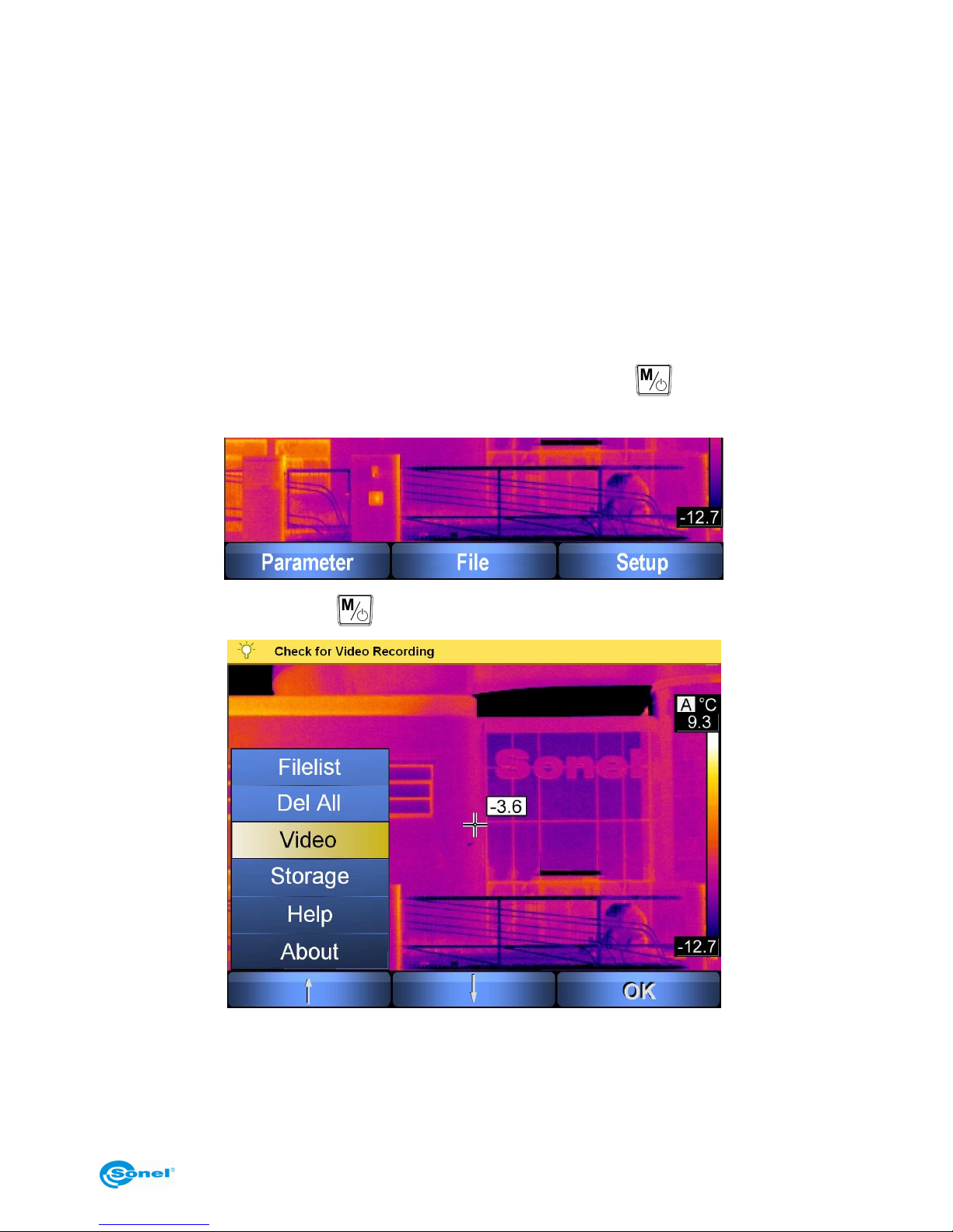
When no menu is displayed on the screen, pressing the button causes the following
options to be displayed:
After selecting "File" (button ), the following sub-menu is opened:
After selecting "Video" the camera is ready for recording thermal video. Select "Record" to
start recording, "Stop" to stop it, and "Play" to playback the last recording. During recording, remaining time and length of the recording are displayed in the top left corner of
the screen. Press the trigger switch (10) to leave this function. Every started recording is
Page 38
SONEL KT-384 THERMAL IMAGER
38
automatically saved in the SD card. Saved recordings can be viewed on the screen, or deleted from the card as single recordings (see section 3.13.1) or all recordings (see section
3.13.2), or subjected to analysis with the Sonel ThermoAnalyze® program.
5.2 Installing camera driver
5.2.1 Hardware requirements
Operating system: Microsoft® Windows 2000 or higher (IE5.0 or higher)
Processor: Pentium 4 2.4GHz or higher
RAM: at least 512 MB
5.2.2 Installation
It is recommended to install the driver before connecting the camera to the computer,
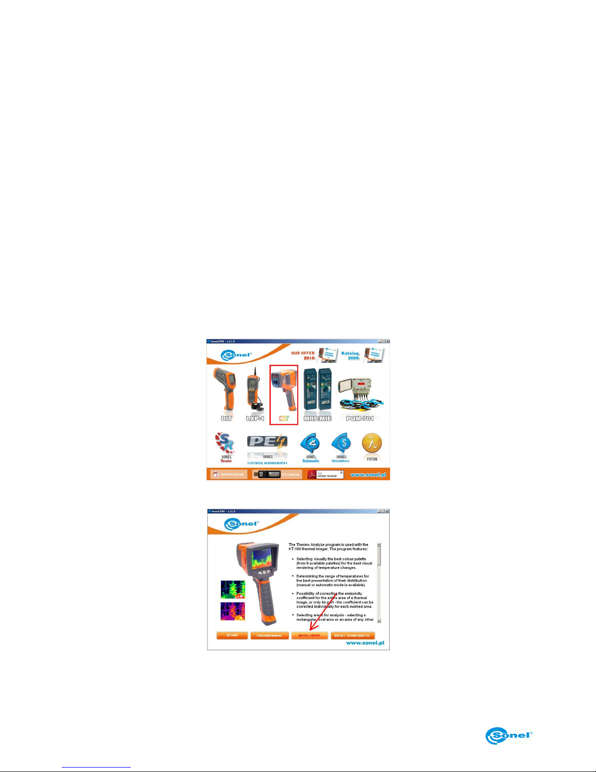
Installer program should start automatically after placing the DVD with software (supplied
with the camera) in the computer drive. If it does not start automatically, run the "autorun.exe" program located in the root directory on the DVD.
After selecting language, a window is opened, where "Thermal Vision Cameras" should
be selected:
and then the "Install Driver" window:
as well as the type of driver, depending on the operating system (32 or 64 bit):
Page 39
OPERATING MANUAL
39
If the camera has been connected to the computer before the installation of the driver, or
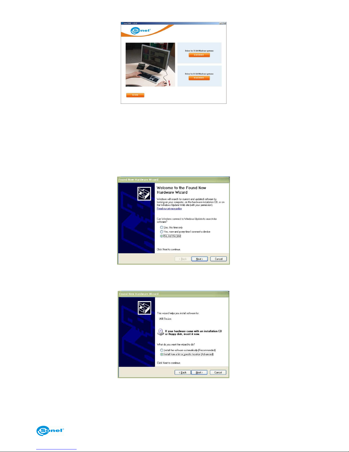
when the original installation disc is not available, the installation process can be performed manually with the available drivers (e.g. downloaded from www.sonel.pl). After
connecting the camera to a USB port of the computer, a Found New Hardware Wizard is
launched; answer "No, not this time" to the question concerning connecting to Windows
Update, and click "Next". Then allow for automatic search for the driver - the Wizard will
search the available media:
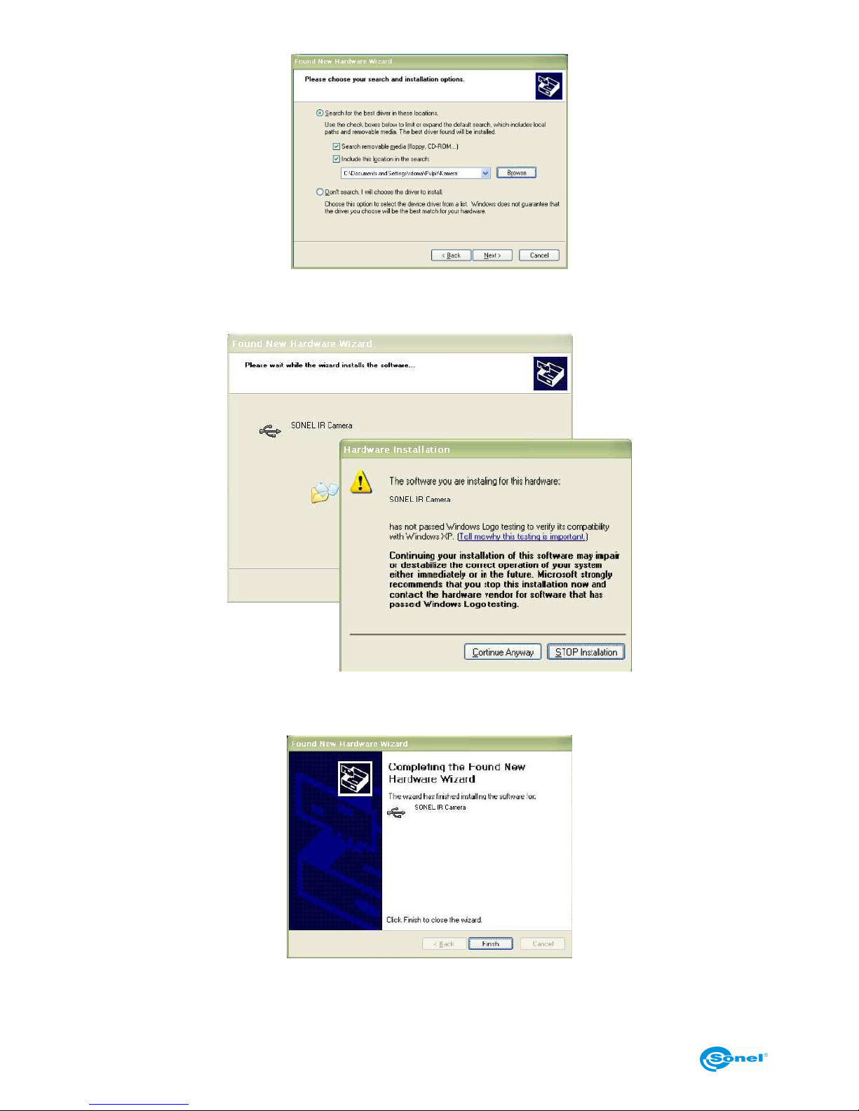
If the driver is not found automatically, select "Install from a list or specific location (Advanced)":
Then point to a folder (drive), where driver files are located and click "Next" to continue:
Page 40
SONEL KT-384 THERMAL IMAGER
40
The installation will start. After reaching the stage presented below, select "Continue Anyway":
When the installation has completed, an appropriate message is displayed - click the "Finish" button.
Page 41
OPERATING MANUAL
41
5.3 Installing the "Sonel ThermoAnalyze®" software
Before starting the installation, it is recommended to close all running programs.
Installer program should start automatically after loading the DVD with software (supplied
with the camera) in the computer drive. If it does not start automatically, run the "autorun.exe" program located in the root directory on the DVD.
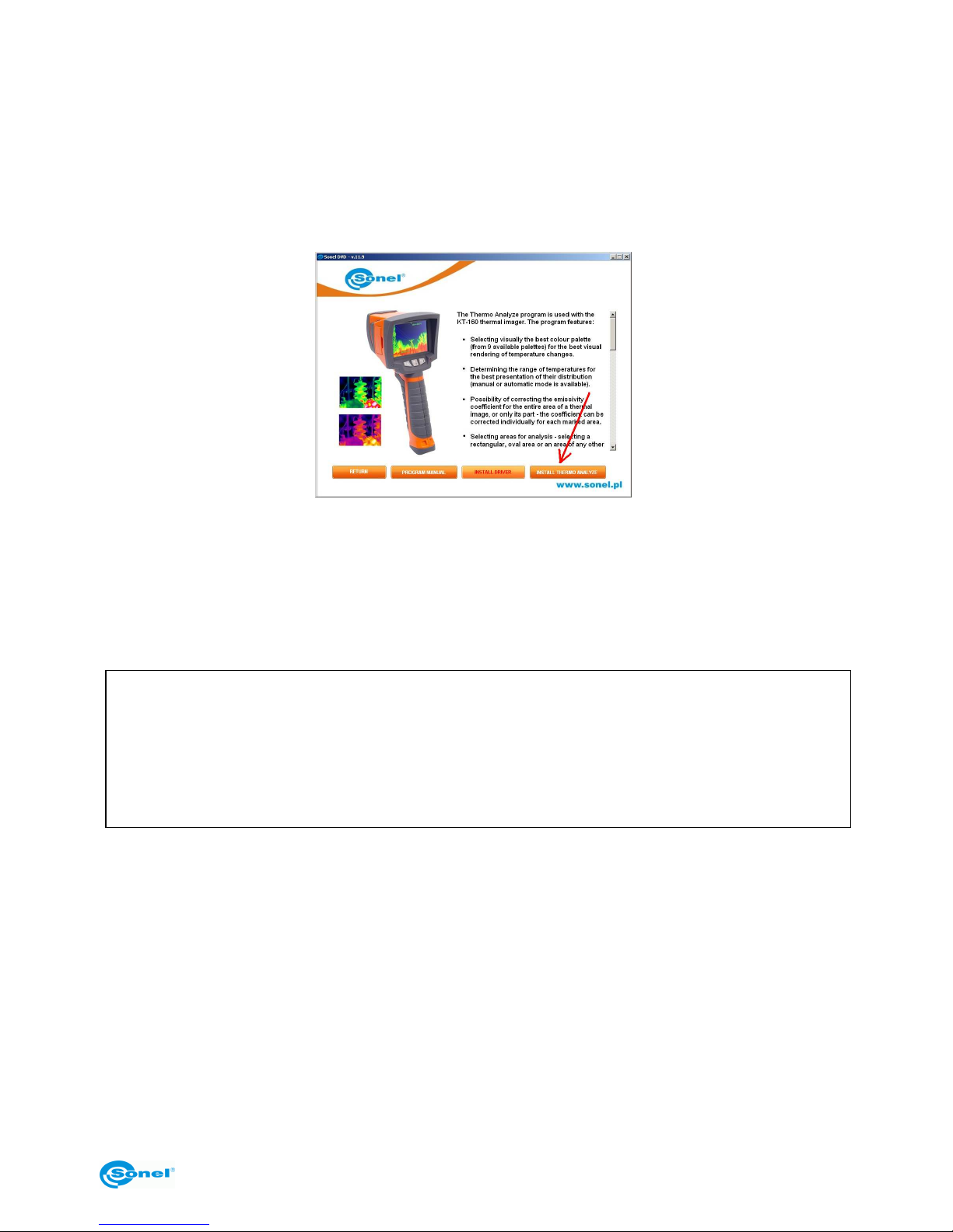
After selecting language, a window is opened, where "Thermal Vision Cameras" should
be selected, and then the "Install Thermo Analyze" window.
The installer will start; follow instructions displayed on the screen.
NOTE: If the default installation folder is not changed, the software will be installed in
C:\Program Files\Sonel ThermoAnalyze. During installation, program shortcuts will be installed on the Desktop as well as in the Start menu.
5.4 Configuring the "Sonel ThermoAnalyze®" software
NOTE.
Below described are only some functions of the "Sonel ThermoAnalyze®"
software, containing instructions related to registering thermal video.
Detailed description of all functions is included in the software manual.
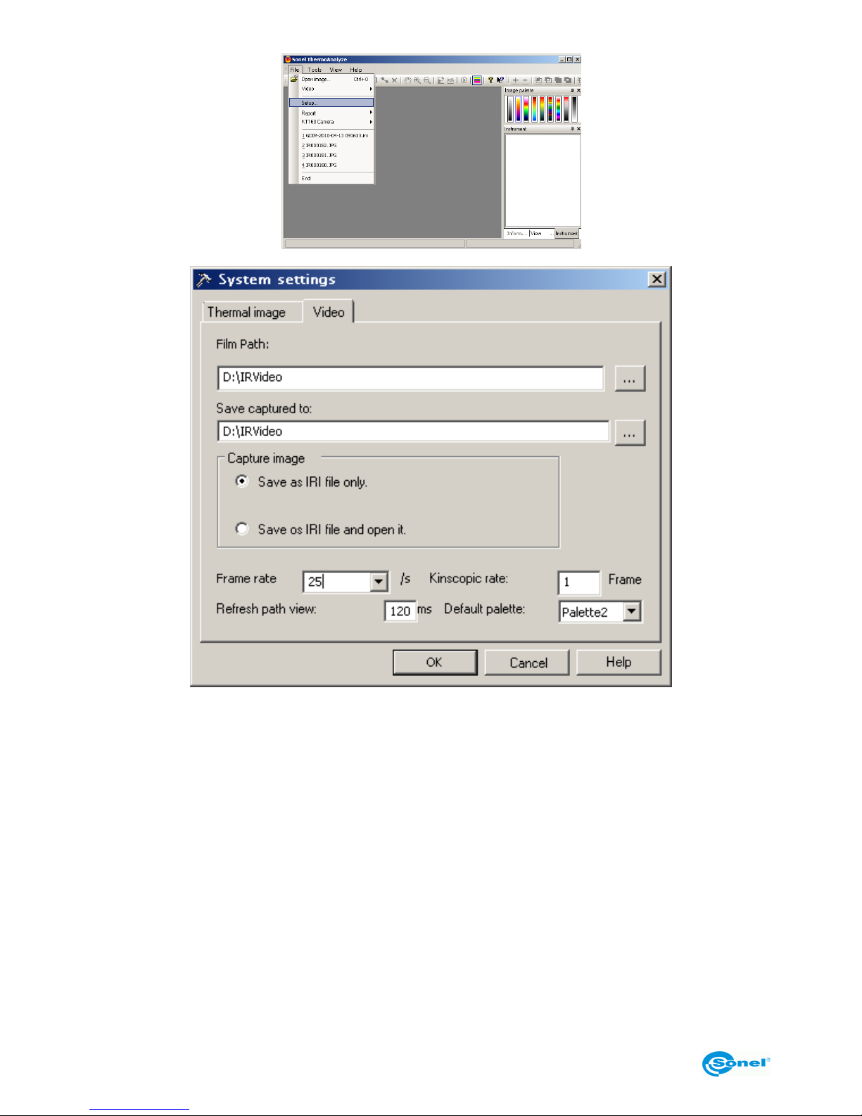
Command "Setup" ("File" menu) is used for defining the location for saving video recordings, captured sequences and images as well as other parameters related to video
recording:
Page 42
SONEL KT-384 THERMAL IMAGER
42
Film Path: sets the path to directory where video recordings will be saved (by default it is
the sub-folder "\IR Video" of the software installation folder).
Save captured to: defines the directory for saving captured images.
Frame rate: defines the number of recorded frames per second (default value 25).
Default palette: sets the palette used in video mode.
Kinescopic rate: defines which consecutive frame is saved (e.g. 1 - every frame; 5 -
every 5th frame). In some situations there is no need to record all frames, this allows for
saving disk space.
Refresh path view: defines the frequency of refreshing information for each point.
Page 43
OPERATING MANUAL
43
5.5 Recording directly to hard disk and playing back thermal video
recordings
5.5.1 Real time thermal video
Command "Firewire Video..." allows for sourcing image directly from the camera.
The camera must be connected to the computer through the port (11) with the supplied
USB cable. The camera should be in the real time mode, no menu or command can be
invoked.
NOTES:
- Before connecting, the camera must be turned on, with all internal tests completed; it is
recommended to connect it to the computer before starting the program.
Page 44
SONEL KT-384 THERMAL IMAGER
44
- During operation in video mode, the camera cannot use the SD memory card - before
starting operation in video mode and connecting the camera to the computer, remove the
card or switch storage location to the built-in "Uflash" memory (see section 3.13.4).
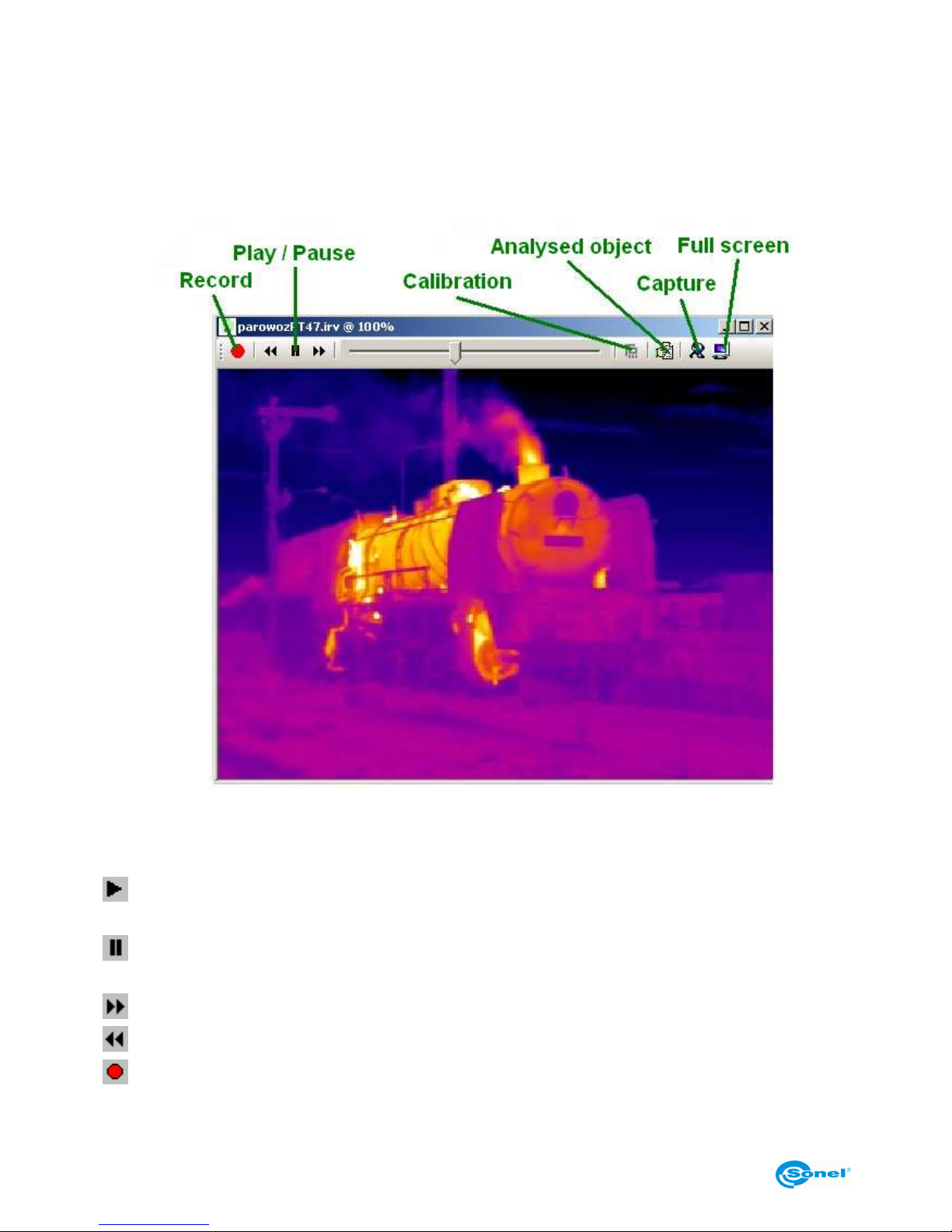
After selecting "KT-384" and with proper connection, a window with real time video image
is opened:
Recording can be started or stopped in real time, the shutter can be operated, and adjustments can be made.
Symbolic functions with short descriptions in video window:
: Starts online preview in the "Firewire Video" mode. Plays back the saved video image
in the video playback mode.
: Stops online preview in the "Firewire Video" mode. Stops playback in the playback
from hard drive mode.
: Fast Forwards frame-after-frame in the playback mode.
: Rewinds frame-after-frame in the playback mode.
: Records video images and saves in continuous mode in the specified directory.
The program saves a file with automatic naming. After stopping and pressing it
Page 45
OPERATING MANUAL
45
again, another recording is made.
NOTE: The button is used for both starting and stopping the recording of ther-
mal video sequence.
NOTE: After placing the cursor over any point, current temperature of this point is dis-
played.
5.5.2 Commands available in thermal video mode only
After performing the procedure described in section 5.4.1, the appearance of the menu
bar (top part of the Sonel ThermoAnalyze® window) changes; functions specific for thermal video mode become available. Described below are only commands related to realtime operation; all commands, including these related to playback and analysis of the recorded material are described in detail in the program operating manual.
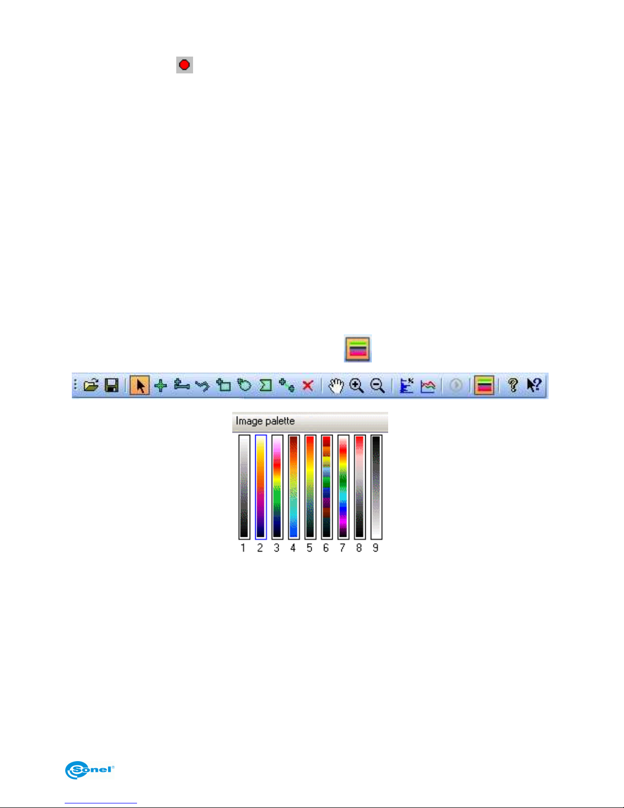
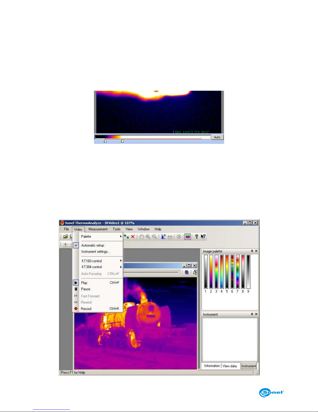
Menu "Video" - command "Palette"
Allows for selecting the palette for rendering thermal image in real time. 9 colour palettes
are available.
Palette change is also available through the "Image palette" window (if the window is not
displayed, it can be invoked by pressing the button on the button bar:
An example image presented in different colours is presented in section 3.11.4, palette 9
is a negative of palette 1.
Menu "Video" - command "Automatic setup"
Allows for automatic or manual setup of the range of colours corresponding to temperatures.
In automatic mode, the system automatically selects optimal settings.
In manual mode, the user can select temperature range for a palette by defining minimal
and maximal temperatures rendered as colours.
NOTE:
Page 46
SONEL KT-384 THERMAL IMAGER
46
Every adjustment of range (see the next command) changes the range and switches the
image into manual mode. Selecting "Automatic setup" at any moment restores automatic
mode.
Menu "Video" - command "Instrument settings..."
Enables adjustment of colour to temperature mapping for each open video file. When selected, an adjustment bar appears under the image (as shown below) allowing for adjustment of range of rendered temperatures:
Optimal settings can be restored at any moment by pressing "Cancel" or with the "Automatic Setup" command (see the above paragraph).
NOTE:
The adjustment bar appears (and vanishes) after double-click on the thermal video image
area.
Other functions available in the "Video" menu
Functions are described in section 5.5.1.
Page 47
OPERATING MANUAL
47
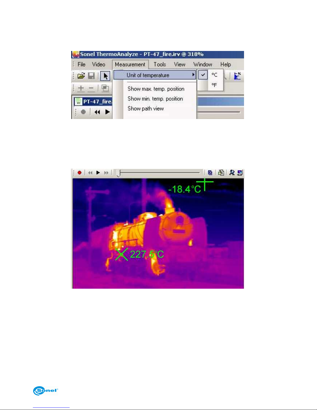
Menu "Measurement" - command "Unit of temperature"
Allows for selecting the unit for displaying temperature (Celsius or Fahrenheit degrees):
Menu "Measurement" - commands "Show max. temp. position" and "Show min.
temp. position"
After selecting any of these commands, the following will be marked on the thermal video
area: symbol "x" - the point of maximal temperature, symbol "+" - the point of minimal
temperature, as well as values of these temperatures:
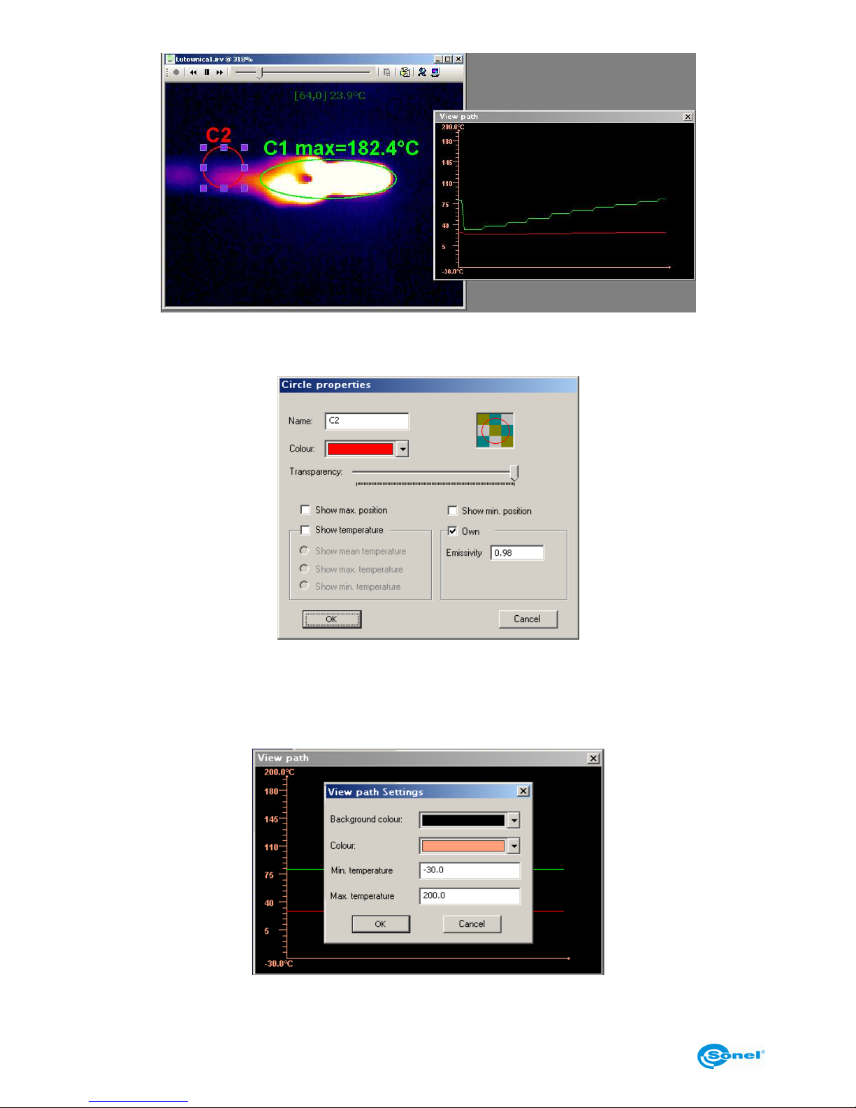
Menu "Measurement" - command "Show path view"
Shows a graph of temperature changes for the marked object of the image (point, section,
area) in real time.
For a point, current temperature is displayed.
For sections and areas maximal, minimal or mean temperature is displayed.
The command should be selected after placing on the image an object defining the area
to be analysed.
Page 48
SONEL KT-384 THERMAL IMAGER
48
After clicking on a given object, a window is opened allowing for changing line colour as
well as transparency of the marked object.
Double-clicking with the left mouse button on the "View path" window opens a dialogue
window, where its settings can be changed: background colour, graph axis colour, minimal and maximal temperatures on the axis. Click "OK" to confirm changes, or "Cancel" to
return to previous values of settings.
NOTE: The graph line is of the same colour as the selected colour of the object.
Page 49
OPERATING MANUAL
49
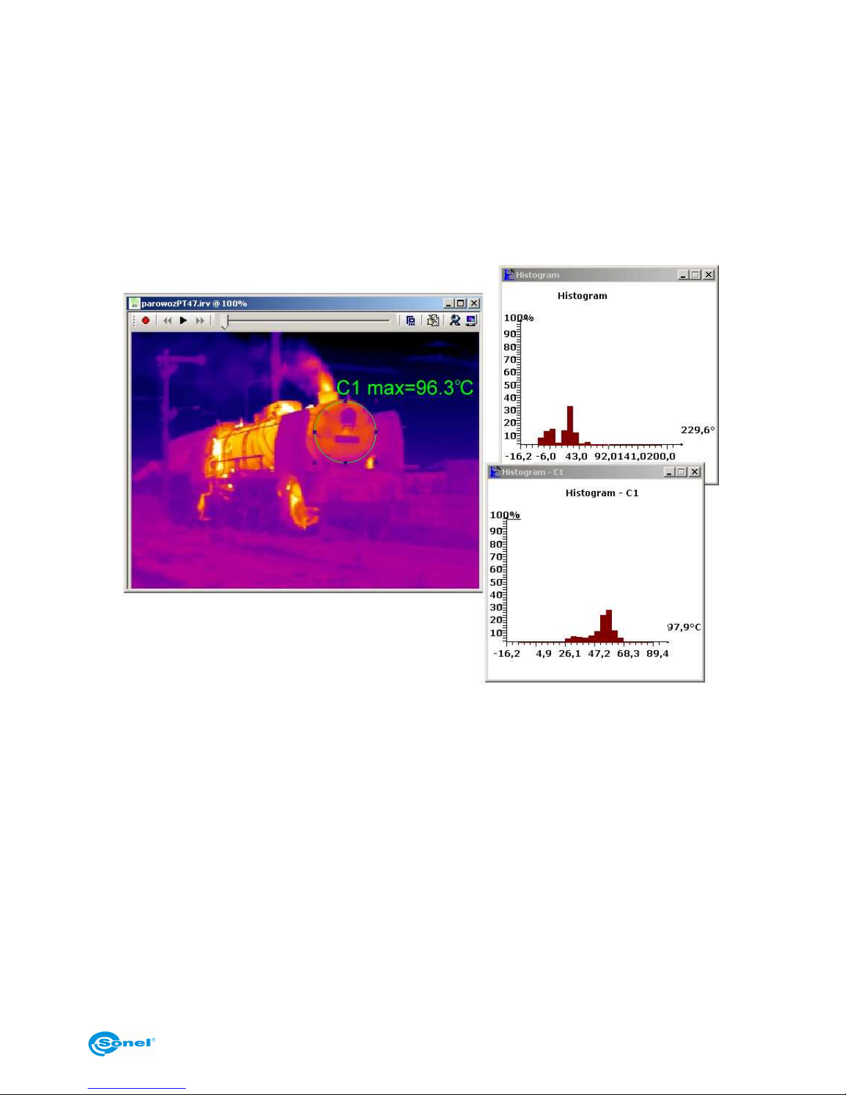
Due to the fact that the colour of graph line depends on the colour of the object, temperature changes in many points and areas can be analysed in one window.
Pressing the F11 function key allows for saving the interim view of the "Path View" window
as a JPG graphic file in the folder with captured video images (see section 5.4).
Menu "Measurement" - command "Histogram"
Selecting the "Image histogram" or "Other histogram" allows for displaying distribution of
temperatures in real time for the entire thermal video image or its specified area:
NOTE: A detailed description of commands allowing for input and handling of areas of
analysis, including description of thermal image analysis capabilities, can be found in the
Sonel ThermoAnalyze® operating manual.
NOTE: The "Isotherm" command is not available in video mode.
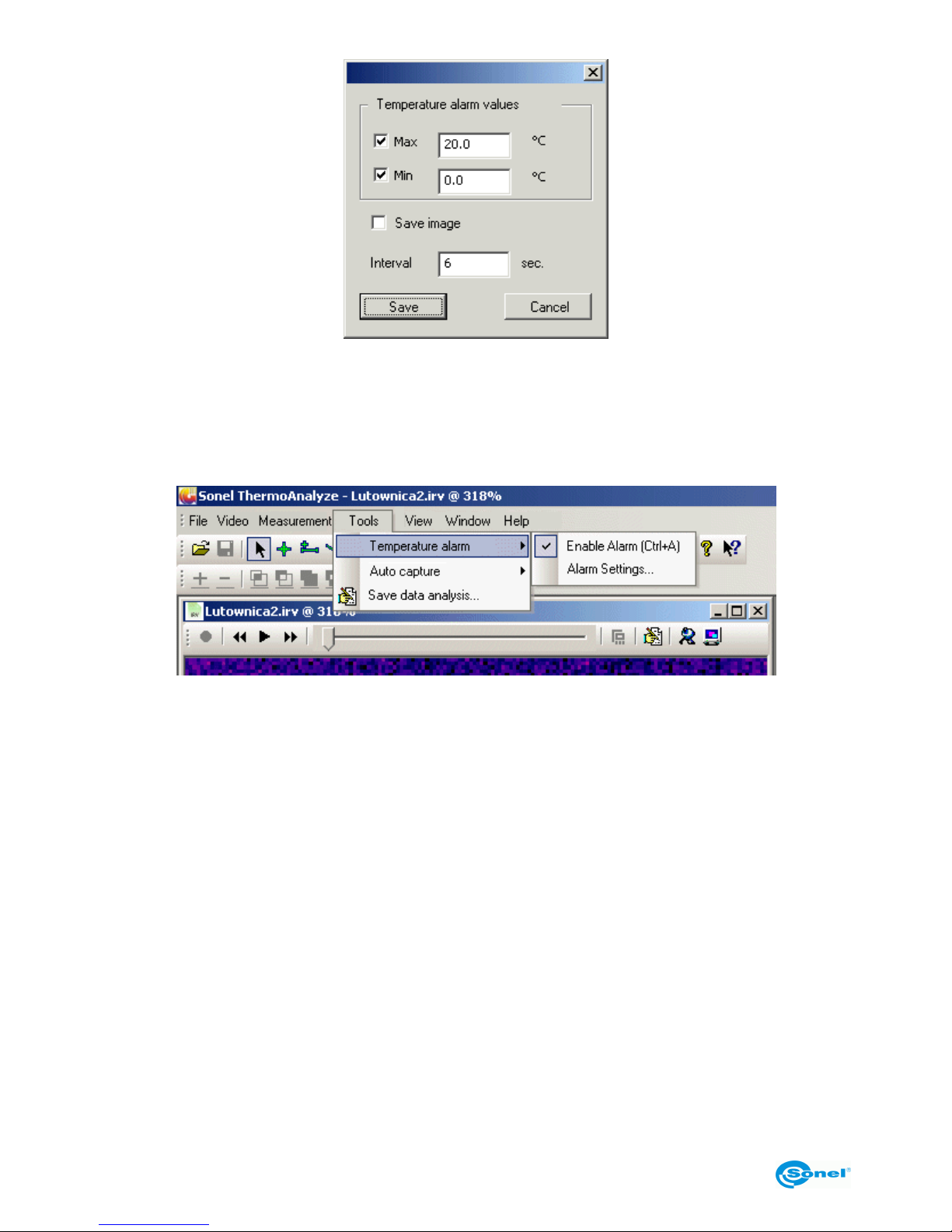
Menu "Tools" - command "Temperature alarm"
This function allows for enabling an alarm, when the specified temperature level is
crossed.
The command "Alarm settings" sets threshold temperatures for the alarm. If "Max" is selected, the alarm will be activated when temperature exceeds the specified value. If "Min"
is selected, the alarm will (also) be activated when temperature falls below the "Min"
value.
Page 50
SONEL KT-384 THERMAL IMAGER
50
If the "Save image" option is selected, when the temperature alarm is triggered, an image
will be captured and saved in the folder with captured images (see section 5.4). Capturing
will be repeated as long as alarm triggering conditions are met, at the interval defined in
the "Interval" field.
The function is enabled by selecting "Enable alarm" from the menu:
Enabled alarm is signalled with the "√" mark.
Method for changing temperature alarm sound is described in the operating manual of the
program.
NOTE: This command can also be invoked with the Ctrl+A key combination.
5.5.3 Saving and analysing data
The "Save data for analysis..." command ("Tools" menu) allows for exporting the results of real time temperature analysis to a TXT file or a graph. It is possible to display a
scatter plot, line or surface graphs of minimal, mean and maximal temperatures with the
use of selected time interval. Detailed description of all functions and examples of analysis can be found in the software manual.
Page 51
OPERATING MANUAL
51
6 Transmitting and analysing data
In order to transmit thermal images saved in the camera, the driver and (in case of using
the built-in memory) the Sonel ThermoAnalyze® software must be installed on the computer (see section 5.2, 5.3).
6.1 Reading external memory (SD memory card)
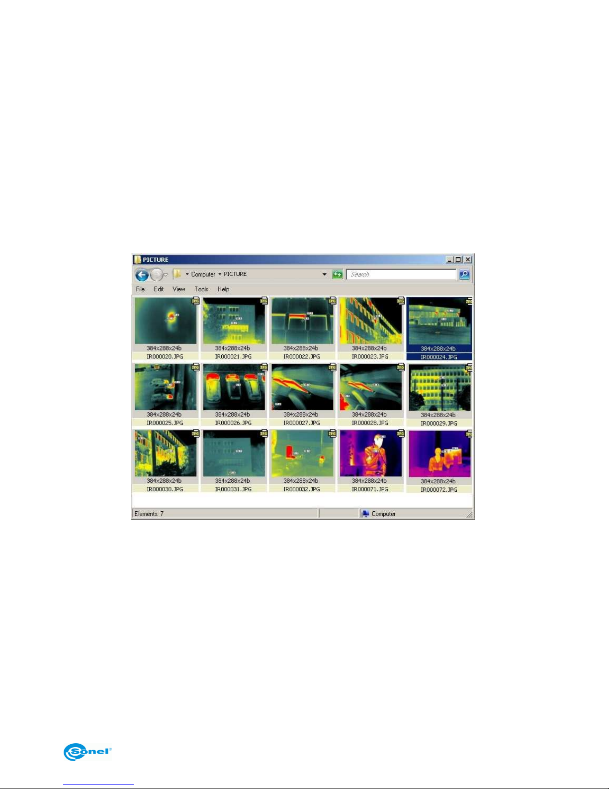
With the SD memory card installed in its slot (14) and the camera is configured for memory card storage (see section 3.13.4), connecting the camera to the computer will make
the card available just as another drive mounted on the computer. Depending on the
mode (see section 3.13.4), the thermal image files are located in the "PICTURE" folder, or
in folders "PICTURE1", "PICTURE2", PICTURE3"; thermal video files are in the "VIDEO"
folder:
NOTES:
- In order to transmit data using the method described above, the "Sonel ThermoAnalyze®" program must not be started.
- When the camera is configured for memory card storage during connecting to the computer, working with the camera is not possible.
- The SD card can also be red with an external card reader (supplied with the camera)
connected to the computer.
6.2 Reading the built-in Uflash memory
Reading data from the built-in (Uflash) memory is possible only through the Sonel ThermoAnalyze® program.
NOTE: Reading the built-in memory is possible only if there is no SD card in the slot (14)
Page 52
SONEL KT-384 THERMAL IMAGER
52
or the camera is configured for built-in memory storage (see section 3.13.4).
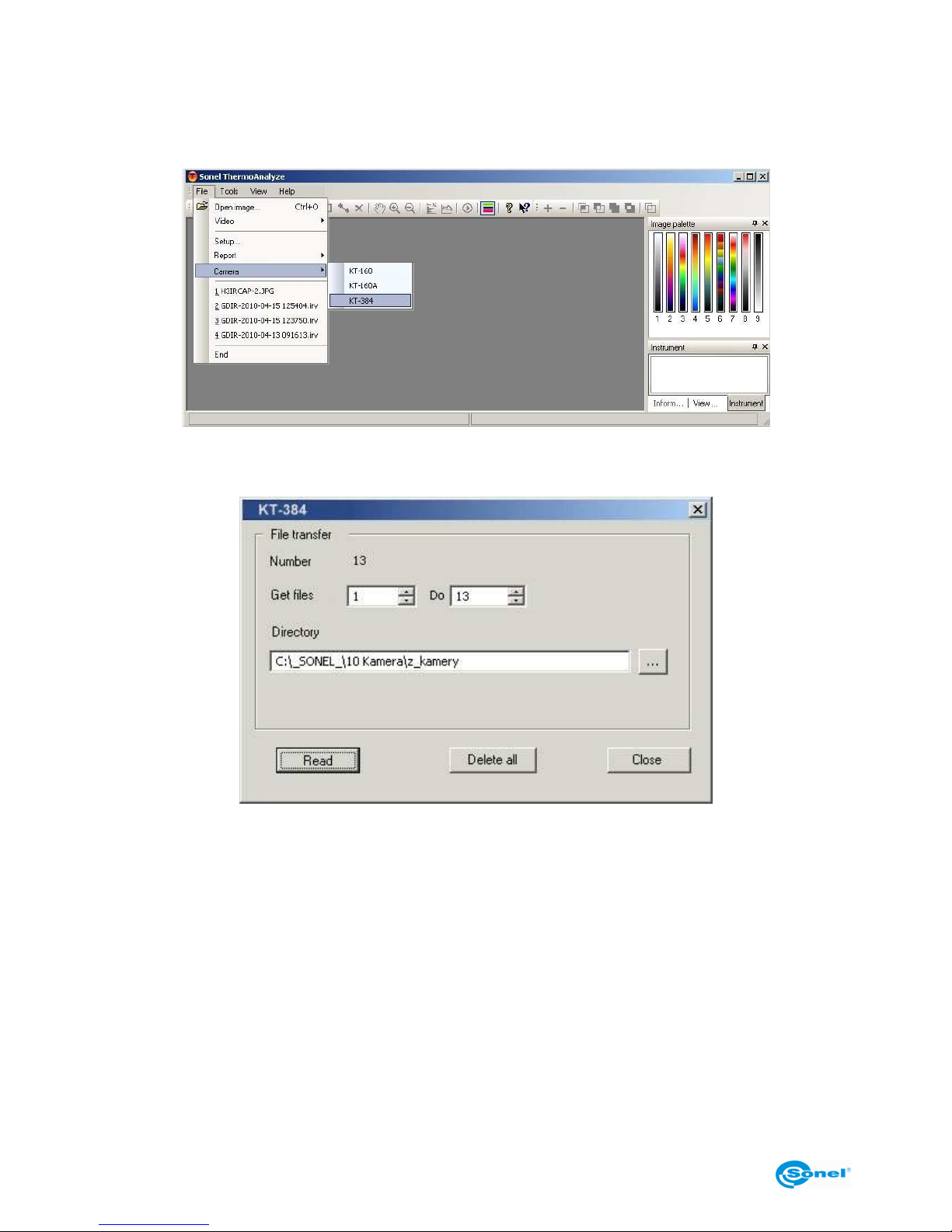
In order to read (copy) the saved thermal images, start the program and connect the
camera (the camera must be turned on with no active menu).
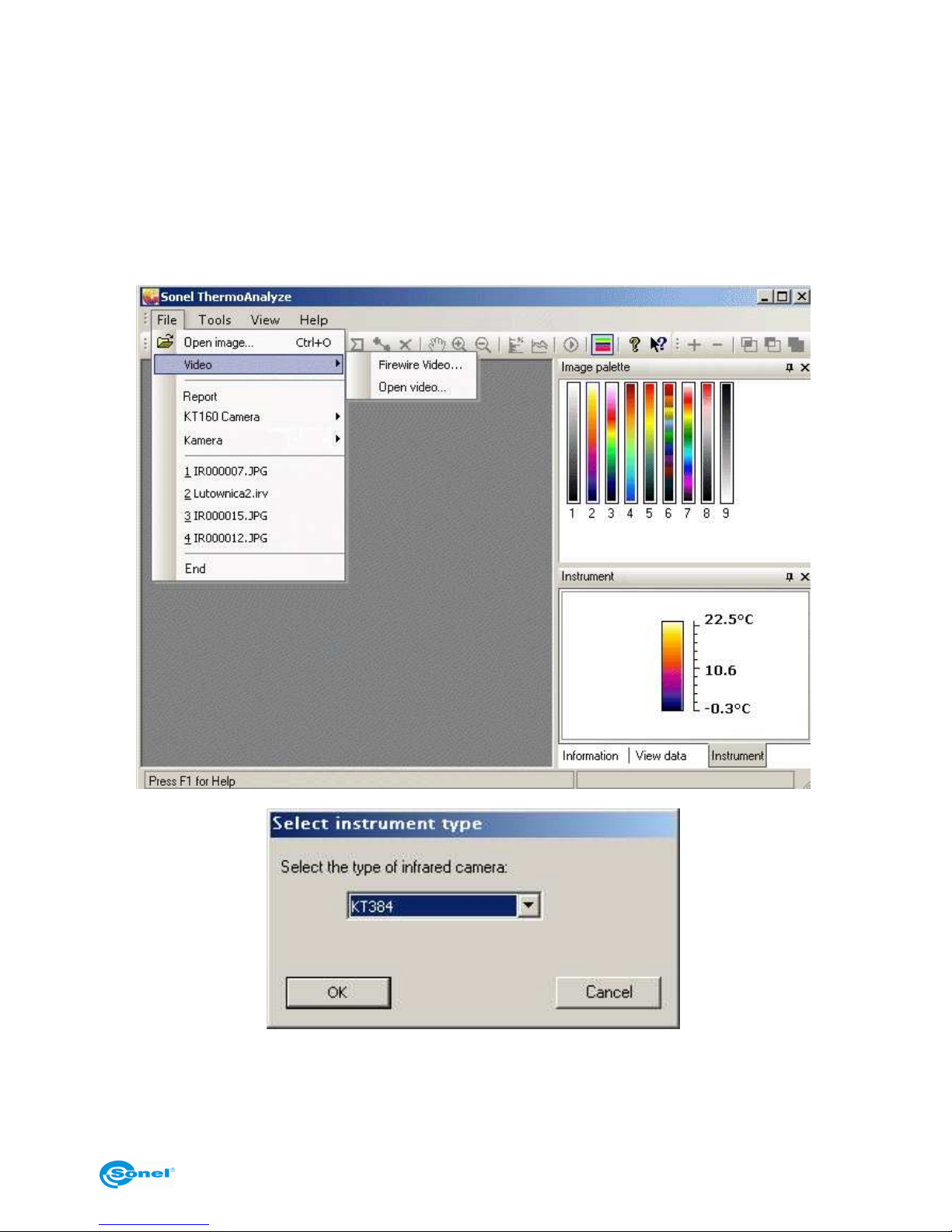
Then select the type of the camera from the "File" menu:
A window will appear allowing for downloading files (all or some of them) saved in the
Uflash memory to a specified folder.
NOTES:
- This function also allows for deleting all files saved in the built-in memory. In order to
remove only some files, follow the procedure described in section 3.13.1.
- The camera can be disconnected from the computer only after the file transfer manager
window is closed.
6.3 Analysing data
The supplied "Sonel ThermoAnalyze®" program allows for performing detailed analysis of
saved thermal images concluded with a report. Detailed description can be found in the
operating manual of the program.
Page 53
OPERATING MANUAL
53
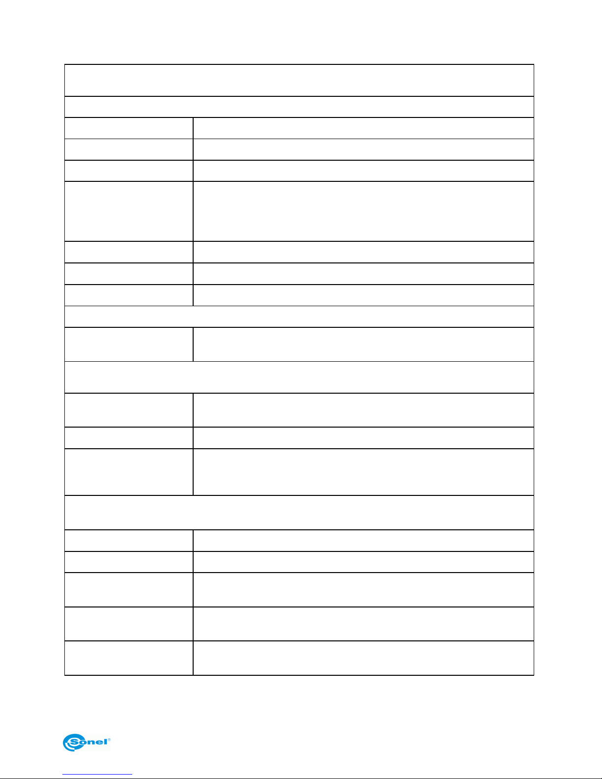
7 Technical specifications
Rendering properties
THERMAL
Detector type Uncooled microbolometric array (384 × 288 pixels, 25 µm)
Spectral range 8-14 µm
Thermal sensitivity ≤0.08°C at 30°C
Field of view /
/ focal length
21.7° X 16.4° / 25 mm (bundled or as an option)
40.53° X 30.96° / 13 mm (bundled or as an option)
13.04° X 9.8° / 42 mm (bundled or as an option)
7.85° X 5.89° / 70 mm (bundled or as an option)
Focus adjustment Manual
Screen refresh rate 50/60Hz
Digital zoom x2, x4 (for focus adjustment)
VISUAL
Recording of
visible image
CMOS sensor, 1600x1200 pixels, "true colour" mode (24 bit)
Image display
External
Display
LCD TFT 3.6 inches, 640*480
Video output PAL / NTSC
InfraFusion
technology
1. Fusion of visible and thermal image - picture-in-picture
2. Fusion of visible and thermal image for a specified range of
temperatures
Measurement
Temperature range -20°C to 400°C
Accuracy * ±2°C or ±2% of readout
Correction of emissiv-
ity
Variable from 0.01 to 1.00 (in increments of 0.01)
Measurement properties
Automatic correlation based on distance, relative humidity, atmospheric transmission and external optics
Correction of atmospheric transmission
Automatic, based on signals received from sensors
*
For non-standard lenses, the manufacturer guarantees the measurement error to be
within specified values only in the central point of the image.
Page 54
SONEL KT-384 THERMAL IMAGER
54
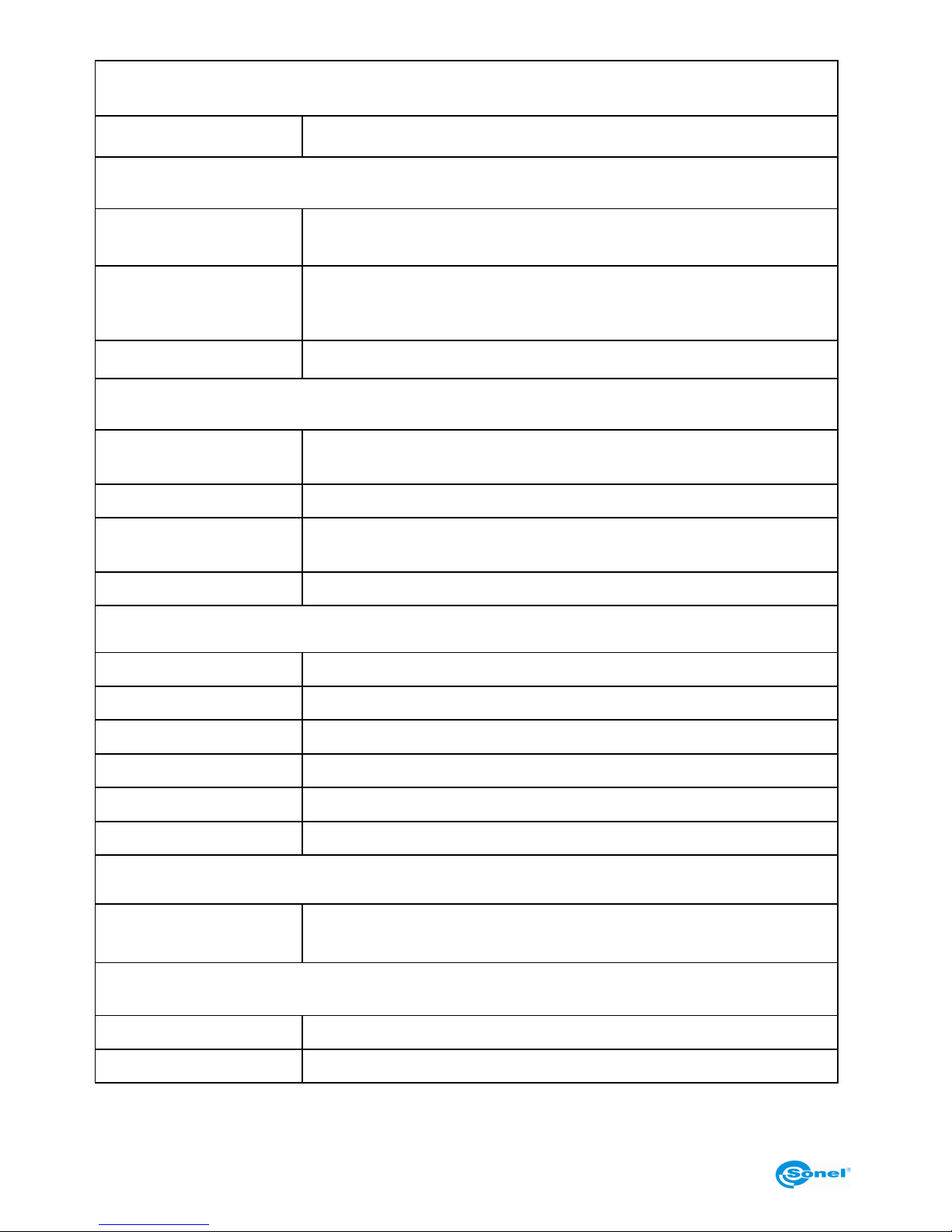
Laser pointer
Classification Semiconductor A1 GalnP, diode laser
Storage of images
Media type
1. Removable SD memory card, 4 GB (optionally 8 GB)
2. Built-in memory 150 MB
Format of files
JPG with thermal data, visible view of the
captured image and voice annotation
Thermal video - IRV format
Voice note Up to 60 seconds / image
Power supply system
Type of batteries
AA rechargeable batteries, capability of using alkaline AA batter-
ies
Charging system Built-in charger
Time of battery opera-
tion
Over 2 hours of continuous operation
External power supply AC power supply adapter 110/230 VAC, 50/60 Hz
Environmental specifications
Working temperature -10°C to 50°C
Storage temperature -20°C to 60°C
Humidity Working and storage: 10% to 95%, without condensation
Enclosure IP54 IEC 60529 enclosure
Shocks Working: 25 G, IEC 60068-2-29
Vibrations Working: 2 G, IEC 60068-2-6
Communications
USB 2.0
Image (thermal and visible), measurement and voice transfer to
a computer; live video image transfer to a computer.
Physical characteristics
Weight 0.79 kg (with rechargeable batteries)
Dimensions 112 mm x 182 mm x 252 mm (with 25 mm lens)
Page 55

OPERATING MANUAL
55
8 Example values of emissivity coefficient
aluminium............................................... 0.05
rough aluminium..................................... 0.07
anodised aluminium................................ 0.25
oxidized aluminium................................. 0.30
asphalt................................................... 0.90
asbestos (sheets, slate)......................... 0.96
asbestos (fibre)...................................... 0.78
Bakelite.................................................. 0.93
dull, matted bronze................................. 0.22
polished bronze...................................... 0.10
rough, porous bronze ............................. 0.55
glazed, rough, regular brick.................... 0.85
rough fireproof brick............................... 0.94
cement................................................... 0.54
cement (concrete).................................. 0.90
chromium............................................... 0.15
polished chromium................................. 0.10
tin........................................................... 0.09
zinc......................................................... 0.05
red brick................................................. 0.93
oil paint................................................... 0.94
fired clay ................................................ 0.91
clay ........................................................ 0.40
graphite.................................................. 0.85
frozen soil............................................... 0.93
rubber..................................................... 0.93
cobalt..................................................... 0.18
quartz..................................................... 0.93
white lacquer.......................................... 0.87
black glossy lacquer............................... 0.87
black dull lacquer ................................... 0.97
silver lacquer.......................................... 0.31
ice.......................................................... 0.97
magnesium............................................. 0.12
oxidised copper...................................... 0.65
black oxidised copper............................. 0.88
polished copper...................................... 0.07
annealed polished copper..............0.01..0.02
brass...................................................... 0.10
oxidised brass........................................ 0.61
polished nickel ....................................... 0.05
shiny lead...............................................0.08
grey lead ................................................0.28
oxidised lead ..........................................0.63
white paper.............................................0.90
black glossy paper..................................0.90
black dull paper......................................0.94
tar paper.................................................0.92
black plastic............................................0.95
platinum..................................................0.10
glazed porcelain .....................................0.92
mercury..................................................0.10
soot ........................................................0.95
lamp soot................................................0.96
silver.......................................................0.03
galvanised steel......................................0.28
oxidised steel..........................................0.88
freshly rolled steel ..................................0.24
rolled steel..............................................0.56
rough steel..............................................0.96
red-rusty steel ........................................0.69
nickel plated steel...................................0.11
enamel....................................................0.90
glass.......................................................0.92
frosted glass...........................................0.96
snow.......................................................0.80
electrical insulation tape......................... 0.95
textiles....................................................0.85
titanium...................................................0.30
carbon....................................................0.90
powdered charcoal................................. 0.96
tungsten .................................................0.13
oxidised tungsten ...................................0.11
gold ........................................................0.02
shiny iron................................................0.16
hot rolled iron..........................................0.77
oxidised iron...........................................0.74
polished iron...........................................0.23
oxidised iron and steel............................0.85
rough casting cast iron ...........................0,81
polished cast iron ...................................0.21
Page 56
SONEL KT-384 THERMAL IMAGER
56
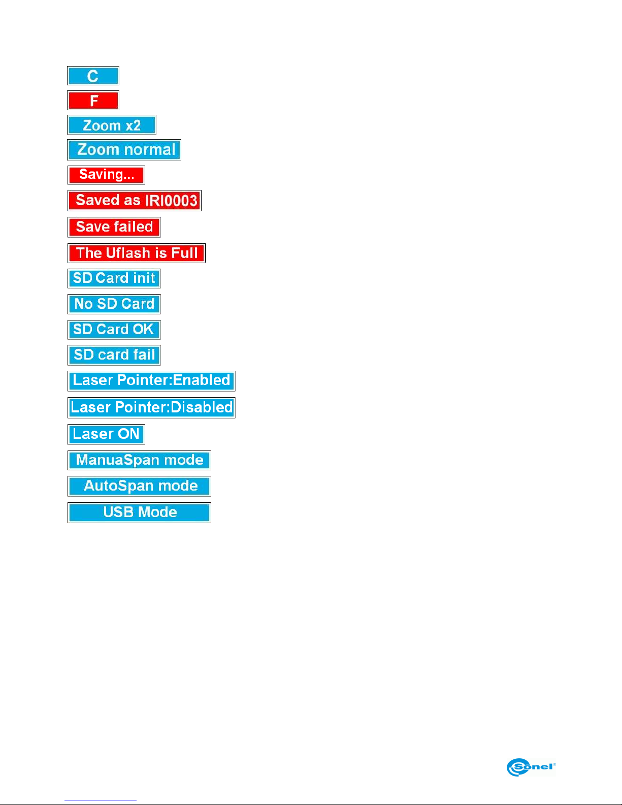
9 Listing of on-screen messages
- camera auto-calibration
- on-screen image frozen, ready for saving
- image enlargement mode (focus adjustment only)
- normal image mode
- saving image
- image saved as ...
- write error, check SD card
- internal memory full
- SD card initialisation mode
- SD card removed
- SD card installed properly
- error during SD card initialisation
- laser pointer ready for use
- laser pointer disabled
- laser pointer is turned ON
- manual mode of temperature mapping
- automatic mode of temperature mapping
- camera connected to the computer, local button control dis-
abled
Page 57
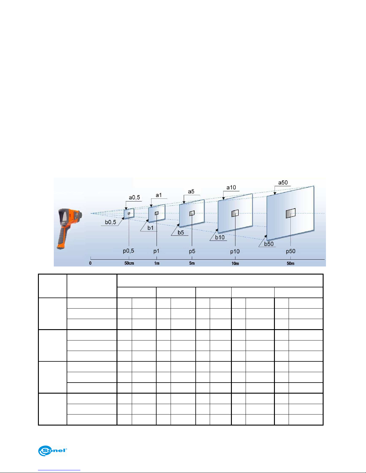
OPERATING MANUAL
57
10 Use of additional accessories
Additional accessories can be used in measurements. To buy the accessories, please
contact the manufacturer or a distributor of Sonel S.A. equipment. Listing of standard and
additional accessories can be found in chapter 13.
10.1 Lens
Depending in the ordered bundle, the camera is equipped with one or several lens from
the following list:
- standard 25 mm, with field of view 21.7° X 16.4°,
- wide angle 40.53° X 30.96° / 13 mm,
- telephoto 13.04° X 9.8° / 42 mm,
- telephoto 7.85° X 5.89° / 70 mm.
The following table presents a comparison of individual lens characteristics (a, b - dimensions of recorded image, p - pixel size):
Distance (m)
Lens Dimensions
0.5 1 5 10 50
width (mm)
a0.5
191.5
a1
383.0
a5
1915
a10
3830
a50
19150
height (mm)
b0.5
144.8
b1
289.5
b5
1448
b10
2895
b50
14475
25 mm
pixel (mm)
p0.5
0.5
p1
1.0
p5
5
p10
10
p50
50
width (mm)
a0.5
357.7
a1
715.4
a5
3577
a10
7154
a50
35770
height (mm)
b0.5
273.3
b1
546.5
b5
2733
b10
5465
b50
27325
13 mm
pixel (mm)
p0.5
1.0
p1
1.9
p5
10
p10
19
p50
95
width (mm)
a0.5
115.1
a1
230.2
a5
1151
a10
2302
a50
11510
height (mm)
b0.5
86.5
b1
173.0
b5
865
b10
1730
b50
8650
42 mm
pixel (mm)
p0.5
0.3
p1
0.6
p5
3
p10
6
p50
30
width (mm)
a0.5
69.3
a1
138.6
a5
693
a10
1386
a50
6930
height (mm)
b0.5
52.0
b1
103.9
b5
520
b10
1039
b50
5195
70 mm
pixel (mm)
p0.5
0.2
p1
0.4
p5
2
p10
4
p50
20
Page 58
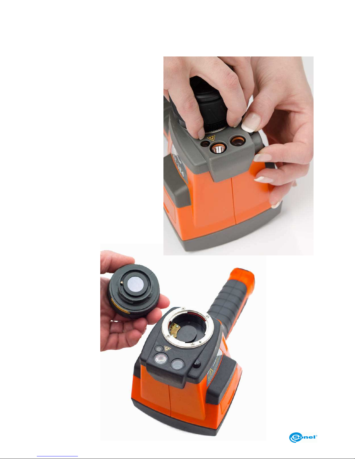
SONEL KT-384 THERMAL IMAGER
58
NOTE! For non-standard lenses, the manufacturer guarantees the measurement error to
be within specified values only in the central point of the image.
Wide-angle lenses may distort the image outside the central area, which is natural and
results from their physical properties.
Replacement of lens must be performed after turning the camera off
and installing the protective lens
cover. To replace the lens, press the
lens lock (18) and turn the lens (16)
clockwise. Note! When turning, do not
hold by the focus adjustment ring (9):
Then mount the new lens by turning it
counter-clockwise, until the lock (18)
snaps in place.
NOTE! Exercise caution to not to
touch any elements inside the camera.
Having changed the lens, change the
"Select lens" setting to correspond to
the new lens (see section 3.12.5).
Page 59
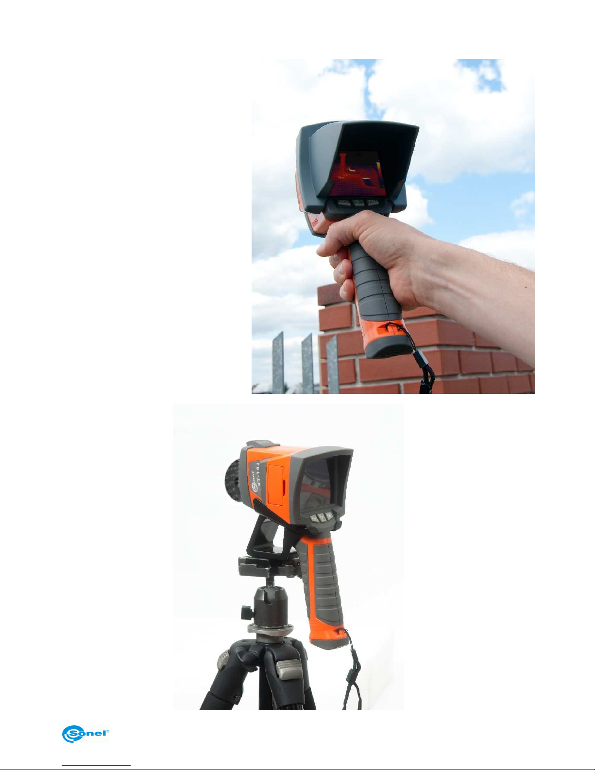
OPERATING MANUAL
59
10.2 Working in intensive
lighting conditions
When working in well lighted
places (strong sunlight or indoor
artificial lighting), the on-screen
image can be barely visible. An
additional sun visor
(WAPOZOSL2) mounted over the
LCD display makes working in
such disadvantageous conditions
easier.
10.3 Working with a tripod
Holding the camera while working
for prolonged time can be tiresome - additionally, any vibrations
cause blurring of captured images. An additional bracket
(WAADASTATYW1) allows for
mounting the camera on a tripod.
Page 60

SONEL KT-384 THERMAL IMAGER
60
11 Cleaning and maintenance
NOTE!
Use the below specified methods of maintenance only.
Camera enclosure - all surfaces, except for optical elements of the camera, can be
cleaned with a soft and moist cloth with generally available mild detergents. Do not use
any solvents or cleaning agents that could scratch the enclosure (powder, paste, etc.).
During cleaning, the camera must be turned off.
Due to the applied anti-reflective coating, optical lens are the most sensitive and at the
same time the most expensive part of the camera (the lens is of key importance to radiometric capabilities of the infrared system). Therefore it is important to close the protective
lens cover after each use of the camera. Optical surfaces should be cleaned only, when
they are visibly fouled. Do not touch exposed surfaces of optical lens with fingers, because fouling left with fingerprints can be harmful to coatings and glass of the lens.
Chemical agents must not be used for cleaning the optical viewfinder, and particularly optics and accessories of the camera. Use a clean, dry and soft cloth for cleaning the body
of the viewfinder; for cleaning the lens, use only the supplied lens cleaning cloth.
12 Calibration
In order to ensure the accuracy and reliability of the thermal imaging camera it is recommended to calibrate the instrument once every 12 months.
For detailed information related to laboratory services call +48 74 85 83 879 or send an
inquiry to [email protected]
NOTE:
The KT-384 thermal imaging camera does not comprise any parts serviceable by the
user. Do not attempt to dismantle or modify the camera on your own. Opening the instrument voids the warranty.
13 Storage
When storing the instrument, observe the following guidelines:
• make sure the camera and its accessories are dry,
• when storing the camera for a prolonged time, remove the batteries,
• allowed are storage temperatures specified in technical specifications,
• in order to avoid complete discharging of rechargeable batteries during prolonged
storage, charge them once in a while.
Page 61

OPERATING MANUAL
61
14 Equipment
Standard bundle supplied by the manufacturer includes:
• KT-384 camera.
• Depending on configuration:
- Replaceable infrared lens of focal length 25 mm (21.7°x16.4°) – bundled or as an
option (WAADAO25)
- Replaceable infrared lens of focal length 13 mm (40.53°x30.96°) – bundled or as
an option (WAADAO13)
- Replaceable infrared lens of focal length 42 mm 13.04°x9.8°) – bundled or as an
option (WAADAO42)
- Replaceable infrared lens of focal length 70 mm (7.85°x5.89°) – bundled or as an
option (WAADAO70)
• Lens cover.
• 4 GB SD Memory Card.
• 2 sets of 6 AA rechargeable batteries.
• Universal AC power supply adapter 110/230 V (WAZASZ8).
• USB cable(WAPRZUSBMNIB5).
• Video cable.
• DVD with the Sonel ThermoAnalyze® software and the driver.
• Operating manual for the camera.
• Operating manual for the Sonel ThermoAnalyze program.
• Hand strap (WAPOZPAS1).
• Carrying case (WAFUTM6).
• Transport bag (WAWALL3).
• External memory card reader with a USB cable (WAADAUSBMEM).
• Gloves, cloth.
Page 62
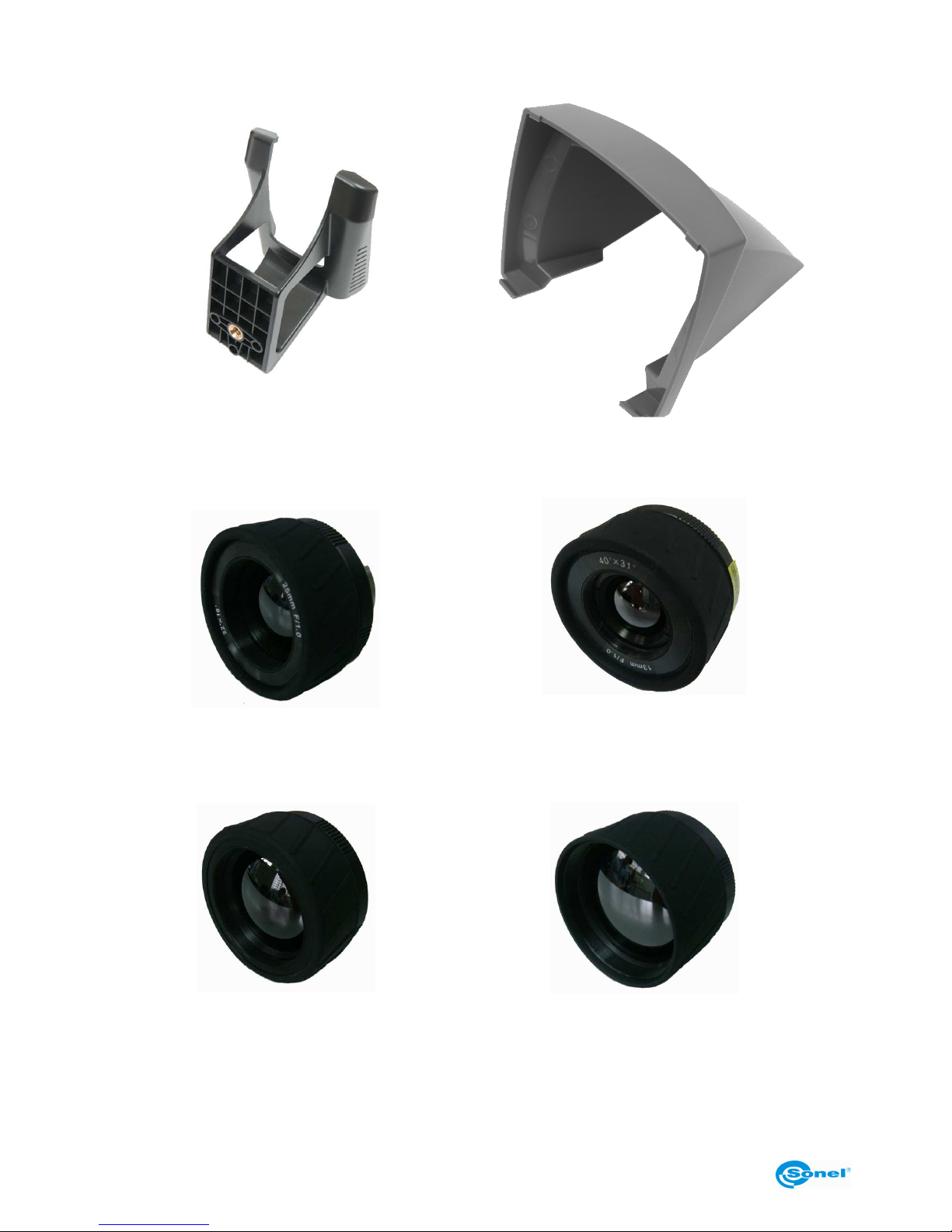
SONEL KT-384 THERMAL IMAGER
62
Optional accessories:
• Bracket for mounting the camera on a
tripod
(WAADASTATYW1)
• Sun visor
(WAPOZOSL2)
• 25 mm IR lens (21.7°x16.4°) – bundled
or as an option
(WAADAO25)
• 13 mm wide angle IR lens
(40.53°x30.96°) – bundled or as an
option
(WAADAO13)
• 42 mm IR lens (13.04°x9.8°) – bundled
or as an option
(WAADAO42)
• 70 mm telephoto IR lens (7.85°x5.89°)
– bundled or as an option
(WAADAO70)
Page 63
OPERATING MANUAL
63
15 Dismantling and disposal
Used-up electrical or electronic equipment must be collected selectively, i.e. must not be
mixed with waste of other types.
Used-up electronic equipment must be delivered to an appropriate collection centre in accordance with regulations related to used-up electrical or electronic equipment.
Before delivering the equipment to the collection centre do not attempt to dismantle any of
its parts.
NOTE:
Follow local regulations related to disposing of packaging, used-
up batteries and rechargeable batteries.
16 Manufacturer
The manufacturer and provider of warranty and post-warranty services for the instrument
is:
SONEL S.A.
ul. Wokulskiego 11
58-100 Świdnica
Poland
tel. +48 74 858 38 60
fax +48 74 858 38 09
E-mail: [email protected]
Web page: www.sonel.pl
NOTE:
Only the manufacturer is authorized
to provide repair services.
Written by Grzegorz Jasiński
Manufactured in PRC
 Loading...