

Page 1

OPERATING INSTRUCTION
NON-CONTACT INFRARED
THERMOMETER
DIT-500
Version 1.6
Page 2

2
Main features of the DIT-500 device are the following:
• rapid detection of temperature changes,
• precise non-contact measurements,
• dual laser lighting,
• modern housing design,
• automatic Data Hold,
• ºC / ºF switch,
• emissivity digitally adjustable from 0.10 to 1.00,
• MAX, MIN, AVG, DIF temperature displays,
• backlight LCD display,
• automatic selection range
• display resolution 0.1ºC (0.1ºF),
• trigger lock,
• set high and low alarms,
• data logger (LOG),
• transmit data to pc with USB.
WIDE RANGE APPLICATION:
Temperature measurements of electric devices, food preparation, safety and fire inspectors, plastic molding, asphalt, marine and
screen printing, measure ink and dryer temperature, Diesel and
fleet maintenance.
Page 3

3
1 INTRODUCTION ..................................................... 25
2 SAFETY .................................................................... 26
3 FUNCTIONAL DESCRIPTION ............................... 27
3.1 D
EVICE DESCRIPTION
..................................................... 27
3.2 LCD
SYMBOLS
............................................................... 28
3.3 B
UTTONS
....................................................................... 29
3.4 D
ISTANCE & SPOT SIZE
................................................... 30
4 HOW IT WORKS...................................................... 30
5 MEASUREMENT OPERATION ............................. 32
6 FUNCTIONAL DESIGN .......................................... 33
6.1 F
UNCTIONALITY
. ........................................................... 33
6.2 F
UNCTIONS OF MODE BUTTON
........................................ 33
6.2.1 MAX,
MIN, DIF, AVG DISPLAY
.............................................. 35
6.2.2 E
MISSIVITY
(ε)
ADJUSTMENT
............................................... 35
6.2.3 C
ONTINUOUS MEASUREMENT (LOCK) ON/OFF
...................... 35
6.2.4 H
IGH ALARM (HAL) ON/OFF
................................................. 35
6.2.5 HAL
ADJUSTMENT
............................................................... 35
6.2.6 L
OW ALARM (LAL) ON/OFF
.................................................. 35
6.2.7 LAL
ADJUSTMENT
............................................................... 35
6.2.8
o
C
/
o
F
..................................................................................... 35
6.3 D
ATA LOGGER
............................................................... 36
6.3.1 S
AVING DATA TO MEMORY
.................................................. 36
6.3.2 R
ECALLING DATA FROM MEMORY
....................................... 36
6.3.3 M
EMORY CLEAR FUNCTION
................................................. 36
6.3.4 USB
FUNCTION
.................................................................... 37
7 BATTERY REPLACEMENT ................................... 37
8 CLEANING AND MAINTENANCE ....................... 38
9 STORAGE ................................................................ 38
10 DISMANTLING
AND UTILIZATION .................... 38
11 ATTACHMENTS ..................................................... 39
11.1 T
ECHNICAL DATA
. ......................................................... 40
11.2 S
TANDARD EQUIPMENT
.................................................. 41
11.3 M
ANUFACTURER
........................................................... 42
Page 4

4
1 Introduction
Thank you for purchase of the IR Thermometer DIT-500. This is
capable of non-contact (infrared) temperature measurements at the
touch of a button. The built-in laser pointer increases target accuracy while the backlight LCD and handy push-buttons combine for
convenient, ergonomic operation.
The Non-contact Infrared Thermometers can be used to measure the temperature of objects’ surface that is improper to be measured by traditional (contact) thermometer (such as moving object,
the surface with electricity current or the objects which are uneasy
to be touched.)
Proper use and care of this meter will provide years of reliable
service.
In the present manual we apply three kinds of warnings. These
are texts in frames, which describe possible dangers both for the
user and the meter itself. The messages starting from the word
‘WARNING:’ describe situations which imply a risk for life or health
should the recommendations presented in the present manual not
be observed. The word ‘ATTENTION!’ introduces a description of a
situation where non-observance of the recommendations presented
in the present manual may imply damage for the meter. Indications
of possible problems are preceded by the word ‘Attention:’.
WARNING:
Before using the instrument acquaint yourself with the present manual and observe the safety regulations and recommendations specified by the manufacturer.
Page 5

5
2 Safety
In order to guarantee proper operation and correctness of the
obtained results it is necessary to observe the following recommendations:
• Use extreme caution when the laser beam is turned on.
• Do not let the beam enter your eye, another person’s eye or the
eye of an animal.
• Be careful no to let the beam on a reflective surface strike your
eye.
• Do not allow the laser light beam impinge on any gas which can
explode.
• It is prohibited to operated the meter:
⇒ If it is damaged and completely or partially out of order.
⇒ If it has been stored for an excessive period of time in inad-
equate conditions (e.g. if it is humid).
• Before commencing a measurement make sure the correct
measurement function has been selected.
• Repairs must be realised solely by an authorised service work-
shop.
Page 6
6
3 Functional description
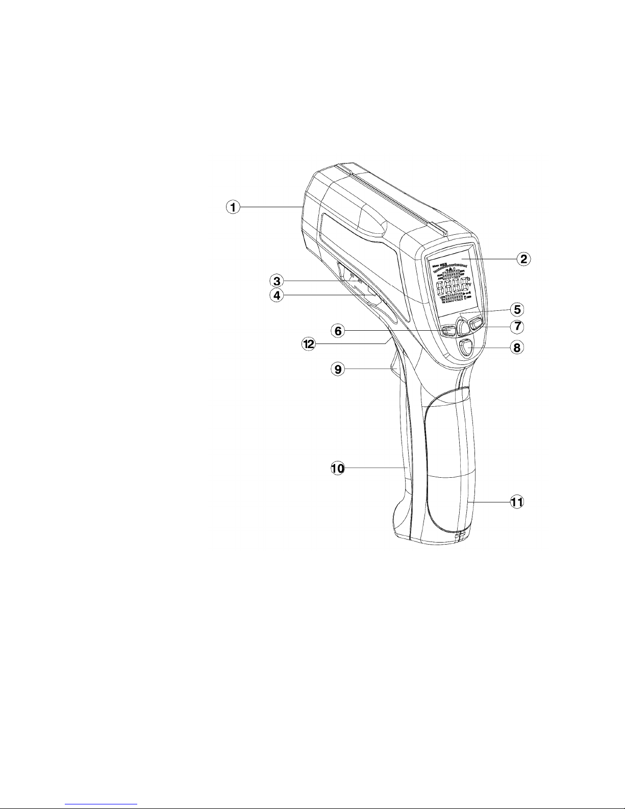
3.1 Device description
① IR sensor
② LCD Display
③ TYPE K IN
④ USB IN
⑤ LIGHT/LASER BUTTON
⑥ UP BUTTON
⑦ DOWN BUTTON
⑧ MODE BUTTON
⑨ MEASUREMENT TRIGGER
⑩ BATTERY COVER
⑪ HANDLE GRIP
⑫ BATTERY COVER BUTTON
Page 7
7
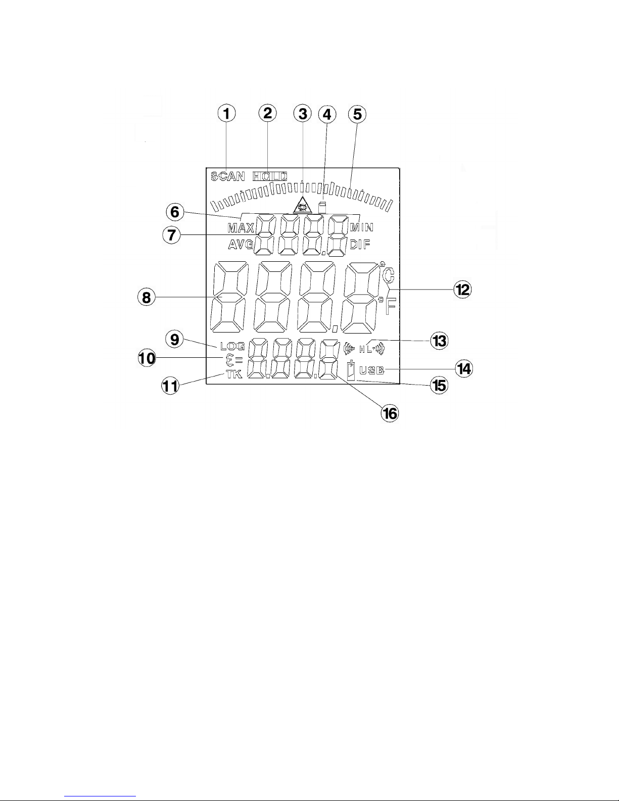
3.2 LCD symbols
① Measuring indication
② Data hold
③ Laser ”on” symbol
④ LOCK symbol
⑤ Analogue scale
⑥ MAX, MIN, AVG, DIF symbols
⑦ Temperature values for the MAX, MIN, AVG, DIF
⑧ Current temperature value
⑨ Data logger symbol
⑩ Emissivity (ε) symbol
⑪ Probe Type K symbol
⑫
O
C or OF symbols
⑬ High alarm (HAL) and low alarm (LAL) symbols
⑭ USB symbol (transmit data to PC)
⑮ Low battery symbol
⑯ Emissivity value, temperature from Type K probe or tempera-
ture from memory
Page 8
8
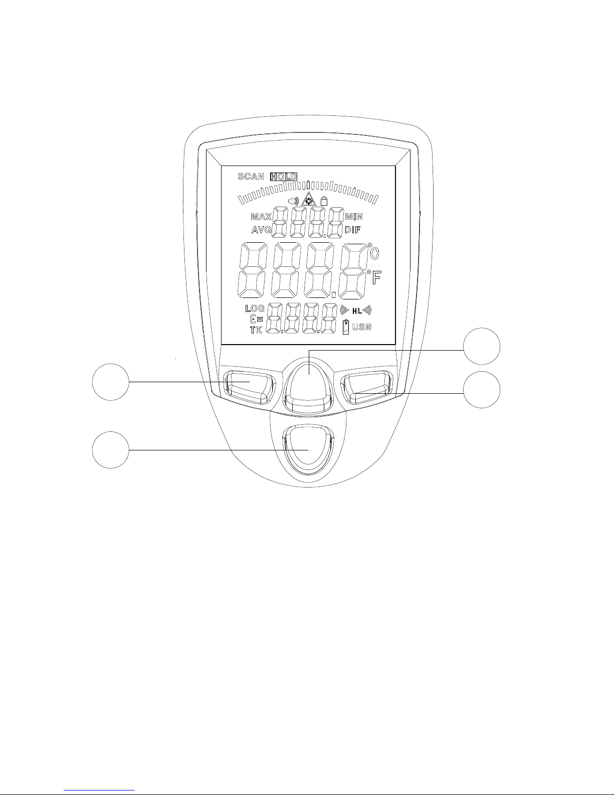
11.1 Buttons
① Laser/Backlight on/off button
② Down button (for ε, HAL, LAL)
③ Up button (for ε, HAL, LAL)
④ Cyclic MODE button
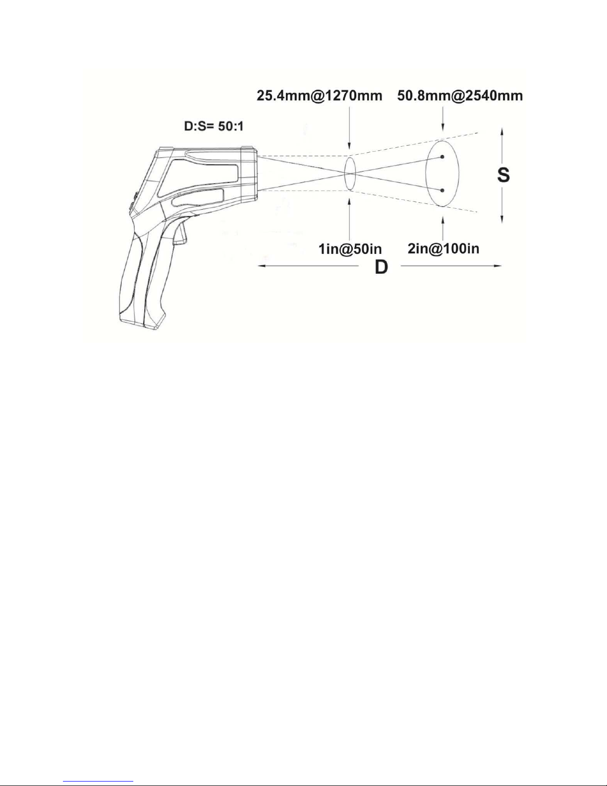
3.4 Distance and spot size
As the distance (D) from the object increases, the spot size (S)
of the area measured by the unit becomes larger. The relationship
between distance and spot size for each unit is listed below. The
focal point of unit is 914mm (36”).
3
4
2
1
Page 9
9
4 How it works
• Infrared
Infrared thermometers measure the surface temperature of an
object. The unit’s optics sense emitted, reflected, and transmitted energy, which is collected and focused onto a detector.
The unit’s electronics translate the information into a temperature reading, which is display on the unit. In units with a laser,
the laser is used for aiming purposes only.
• Field of View
Make sure that the target is larger than the unit’s spot size.
The smaller the target, the closer you should be to it. When
accuracy is critical, make sure the target is at least twice as
large as the spot size.
• Distance and spot size
As the distance (D) from the object increases, the spot size
(S) of the area measured by the unit becomes larger.
• Locating a hot Spot
To find a hot spot aim the thermometer outside the area of interest, then scan across with an up and down motion until you
locate hot spot.
Page 10

10
• Reminders
- Not recommended for use in measuring shiny or polished
metal surfaces (stainless steel, aluminum, etc.). See Emis-
sivity.
- The unit cannot measure through transparent surfaces such
as glass. It will measure the surface temperature of the glass
instead.
- Steam, dust, smoke, etc., Can prevent accurate measurement by obstructing the unit’s optics.
• Emissivity
Emissivity is a term used to describe the energy-emitting
characteristics of materials.
Most (90% of typical applications) organic materials and
painted or oxidized surfaces have an emissivity of 0.95 (preset in the unit). Inaccurate readings will result from measuring
shiny or polished metal surfaces. To compensate, cove the
surface to be measured with masking tape or flat black paint.
Allow time for the tape to reach the same temperature as the
material underneath it. Measure the temperature of the tape
or painted surface.
The DIT-500 can compensate additional error of emissivity
other than 0.95. In this purpose, enter correct value of measured substance emissivity.
Page 11

11
Emissivity values
Substance
Thermal
emissivity
Substance
Thermal
emissivity
Asphalt 0,90 to 0,98 Cloth (black) 0,98
Concrete 0,94 Human skin 0,98
Cement 0,96 Lather 0,75 to 0,80
Sand 0,90 Charcoal
(powder)
0,96
Earth 0,92 to 0,96 Lacquer 0,80 to 0,95
Water 0,92 to 0,96 Lacquer (matt) 0,97
Ice 0,96 to 0,98 Rubber (black) 0,94
Snow 0,83 Plastic 0,85 to 0,95
Glass 0,90 to 0,95 Timber 0,90
Ceramic 0,90 to 0,94 Paper 0,70 to 0,94
Marble 0,94 Chromium oxides 0,81
Plaster 0,80 to 0,90 Copper oxides 0,78
Mortar 0,89 to 0,91 Iron oxides 0,78 to 0,82
Brick 0,93 to 0,96 Textiles 0,90
5 Measurement operation
• Hold the meter by it’s handle grip and point it toward the sur-
face to be measured.
• Pull and hold the trigger to turn the meter on and begin testing.
The display will light if the battery is good. Replace the battery
if the display does not light.
• Release the trigger and the HOLD display icon will appear on
the LCD indicating that the reading is being held. In HOLD sta-
tus, press the ①①①① button to turn on/off the laser and turn on/off
backlight.
• The meter will automatically power down after approximately 7
seconds after the trigger is released (unless the unit is locked
on).
Page 12

12
Note: Measurement considerations
Holding the meter by its handle, point the IR Sensor toward the
object whose temperature is to be measured. The meter automatically compensates for temperature deviations from ambient temperature. Keep in mind that it will take up to 30 minutes to adjust to
wide ambient temperatures are to be measured followed by high
temperature measurements.
Some time (several minutes) is required after the low (and before the high) temperature measurements are made. This is a result
of the cooling process, which must take place for the IR sensor.
6 Functional design
6.1 Functionality
• In the measuring time, pressing MODE keys to display MAX
value, MIN value, DIF value , AVG value or LOG value.
• In the measuring time, if the Type K thermocouple is not
connected, you can adjust ε by pressing up/down key.
• In the HOLD mode, you can adjust OC/OF by pressing up/down
key.
• You can turn on/off the backlight/laser by pressing
LIGHT/LASER key ①
① ①
① at any state.
• To set values for the high alarm (HAL), low alarm (LAL) and
emissivity (ε), press the MODE button until the appropriate code
appears in the display, press the UP and DOWN buttons to
adjust the desired values.
6.2 Functions of MODE button
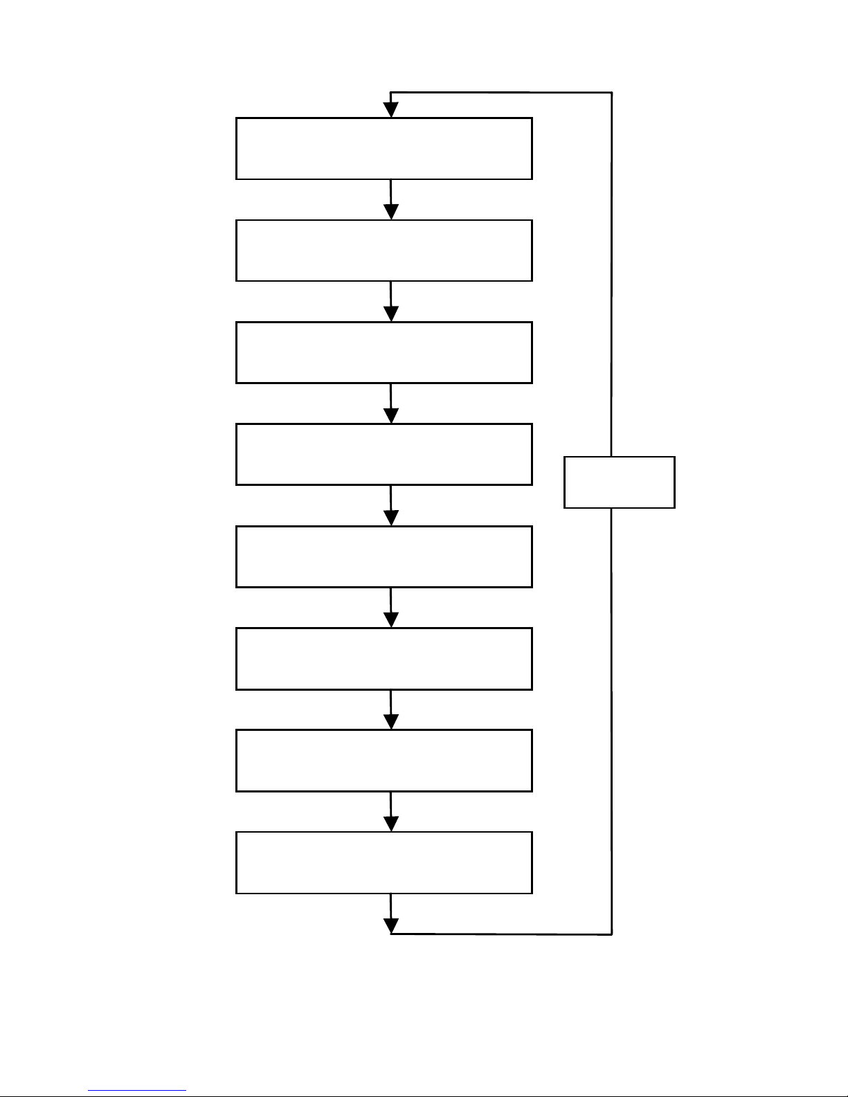
In the HOLD mode, press the mode button also allows you to
access the set state: MAX, MIN, DIF, AVG or LOG display ->
emissivity (ε) -> lock on/off (continuos measuremet) -> high alarm
(HAL) on/off -> HAL adjustment -> low alarm (LAL) on/off -> LAL
adjustment -> OC/OF.
Each time you press set you advance through the mode cycle.
The diagram shows the sequence of functions in the mode cycle.
Page 13
13
LAL on/off
HAL adjustment
MAX, MIN, DIF, AVG, LOG
OC/O
F
LAL adjustment
ε
adjustment
LOCK on/off
HAL on/off
MODE
Fig. 1.
Sequence of MODE button.
Page 14

14
6.2.1 MAX, MIN, DIF, AVG display
MAX (maximum) - Maximum value of measurement.
MIN (minimum) - Minimum value of measurement.
DIF (difference) - Difference value of measurement.
AVG (average) - Average value of measurement.
Adjustable display by pressing UP/DOWN button
6.2.2 Emissivity (εεεε) adjustment
The emissivity (ε) digitally adjustable from 0,10 to 1,0 by
pressing UP/DOWN button.
6.2.3 Continuous measurement (LOCK) on/off
The lock mode is particularly useful for continuous monitoring of
temperatures. Press the UP button or DOWN button to turn on or
off. Press the measurement trigger to confirm the lock
measurement mode. The IR thermometer will continuously display
the temperaure until press again the measurement trigger.
6.2.4 High alarm (HAL) on/off
Turn on or off high alarm by pressing UP/DOWN button.
6.2.5 HAL adjustment
Please adjust high alarm value by pressing UP/DOWN button.
6.2.6 Low alarm (LAL) on/off
Turn on or off low alarm by pressing UP/DOWN button.
6.2.7 LAL adjustment
Please adjust low alarm value by pressing UP/DOWN button.
6.2.8 OC/OF
Pressing UP/DOWN button to change the temperature unit (℃
or ℉).
Page 15

15
6.3 Data logger
6.3.1 Saving data to memory
Your thermometer is capable of storing up to 100 measurements.
To store data from an infrared reading, pull the trigger. While
holding the trigger, press the MODE button until LOG appears in
the lower left corner of the display (a log location number will be
shown in upper display).
Aim the unit at the target area you want to record and press the
LASER/BACKLIGHT button. The recorded temperature will appear
in the lower display. To select another log location, press the UP or
DOWN keys.
If no temperature has been recorded in the shown LOG location, four dashes will appear in the lower display.
6.3.2 Recalling data from memory
To recall stored data after the unit shuts off, press the MODE
button until blinking MAX appears on the LCD. Press the UP or
DOWN button to call blinking LOG symbol on LCD. Press trigger to
accept.
A LOG location number will be shown on upper display and the
stored temperature for that location will be display on lower display.
To move to another LOG location, press the UP or DOWN keys.
6.3.3 Memory clear function
This function can only be used when the unit is in LOG mode.
You should only use the LOG clear function if you want to clear all
the Log location data that is stored in unit’s memory. The “LOG
clear” function works as follows:
• while in LOG mode, press and hold the trigger, and then press
the DOWN arrow button until you reach LOG location “000”.
Note: This can only be done when the trigger is pulled. LOG loca-
tion “000” cannot be accessed, by using the UP arrow button.
• when LOG location “000” shows in the display, press the
LASER/BACKLIGHT button. A tones will sound, and the LOG
Page 16
16
location will automatically change to “001”, signifying that all
data locations have been cleared.
6.3.4 USB function
This device affords transmitting the IR and Type K
measurement data to the PC via USB.
For turn on or off USB function: press LIGHT/LASER button
until “USB” sign appears in the right lower corner of the LCD. The
USB function turn on. Then, press the LIGHT/LASER button again
until “USB” sign disappears. Thus, the USB function shut off.
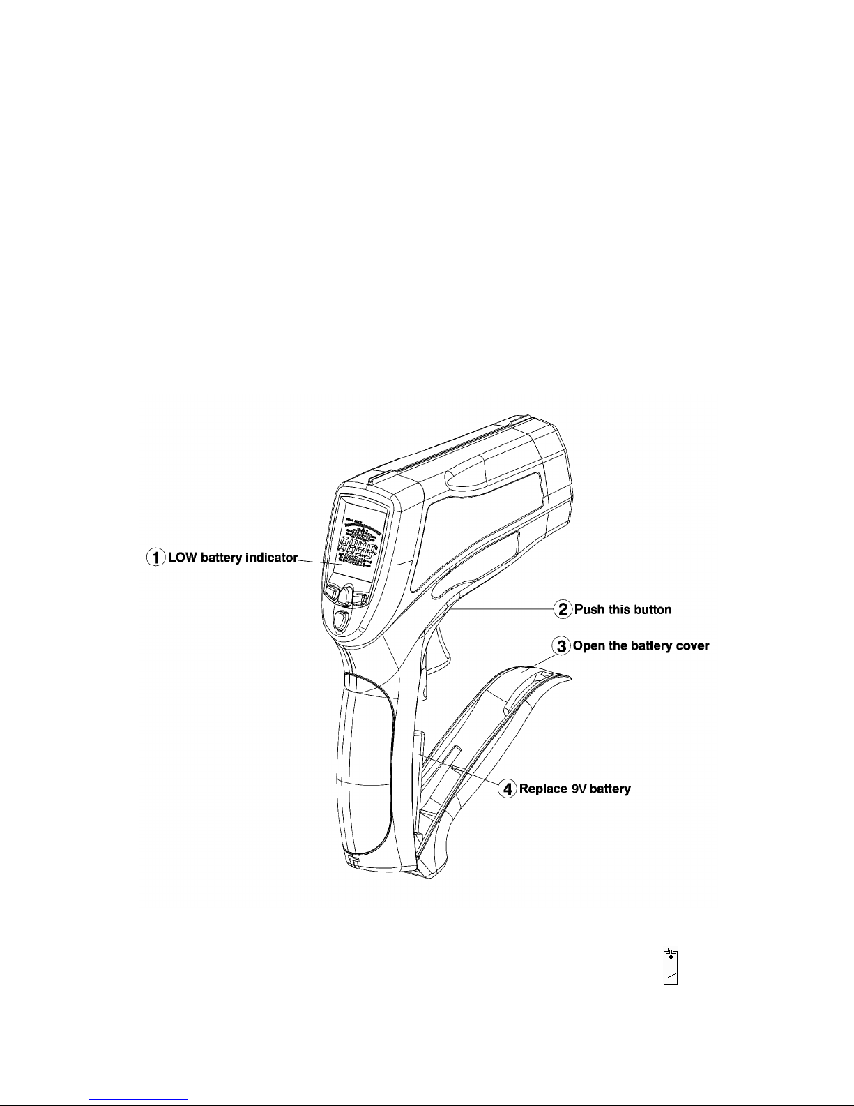
7 Battery replacement
As battery power is not sufficient, LCD will display “ ”. Replacement with one new battery type 9V is required.
Page 17

17
Attention:
When making measurements with a battery's mnemonic on,
one must take into account additional indefinite measurement uncertainty or unstable working of the meter.
Open battery cover, then take out the battery from instrument
and replace with a new 9-Volt battery and place the battery cover
back.
8 Cleaning and maintenance
• Repairs or service are not covered in this manual and should
only be carried out by qualified trained technician.
• Periodically, wipe the body with a dry cloth. Do not use
abrasives or solvents on this instrument.
• For service, use only manufacturer’s specified parts.
9 Storage
In the case of storage of the device, the following recommendations must be observed:
• Make sure the meter and its accessories are dry.
• In the case the meter is to be stored for a prolonged period of
time, the batteries must be removed from the device.
10 Dismantling and utilization
Worn-out electric and electronic equipment should be gathered
selectively, i.e. it must not be placed with waste of another kind.
Worn-out electronic equipment should be sent to a collection
point in accordance with the law of worn-out electric and electronic
equipment.
Before the equipment is sent to a collection point, do not dismantle any elements.
Observe the local regulations concerning disposal of packages,
worn-out batteries and accumulators.
Page 18

18
11 Attachments
11.1 Technical data
Type K temperature range
IR temperature range
Temperature
range
D:S
Reso-
lution
Basic accuracy
-50,0…999,9℃
-58,0…999,9℉
50:1
0,1℃
0,1℉
-50…20℃
-58℉…68℉
±2,5℃
±4,5℉
1000…1600℃
1000…2912℉
1℃
1℉
20…400℃
68…752℉
±(1,0% m.v.
+ 1℃ or
1,8℉)
400…800℃
752…1472℉
±(1,5% m.v.
+ 2℃
or 3,6℉)
800…1600℃
1472…2912
℉
±2,5% m.v.
Operating temperature of: 23 to 25℃ (73 to 77℉)
“m.v.” means measured value of standard.
Other technical data
Temperature
range
Resolution
Basic accuracy
-50,0…999,9℃
-58,0…999,9℉
0,1℃
0,1℉
±(1,5% m.v. + 3℃)
±(1,5% m.v. + 5℉)
1000…1370℃
1000…2498℉
1℃
1℉
±(1,5% m.v. + 2℃)
±(1,5% m.v + 3,6℉)
Page 19

19
a) response time ………………….………….…………...….…150ms
b) spectral response …………….…………….…………….8…14µm
c) emissivity…………………...digitally adjustable from 0.10 to 1.00
d) over range indication……..….……..…………LCD will show “----”
e) polarity………………..….automatic, (-) sign for negative polarity
f) diode laser……………output <1mW, wavelength 630~670nm,
class 2 laser product
g) operating temperature………..…………...0 to 50℃ (32 to
122℉)
h) storage temp…………………….……...–10 to 60℃ (14 to 140℉)
i) relative humidity……………………..…..10%~90% RH operating
…………………………………………………….<80% RH storage
j) memory……………………………………………………..100 cells
k) PC interface……………………………………………………..USB
l) power supply……………9V battery, NEDA 1604A or IEC 6LR61
m) safety…………………………………….…“CE” Comply with EMC
n) weight ..................................................................................350g
o) size..……………………………………….…… 230 x 155 x 54mm
11.2 Standard equipment
The standard set provided by the manufacturer includes the following components:
• The DIT-500 meter,
• 9V battery (1 piece),
• USB cable,
• PC software,
• K Type probe,
• mini tripod,
• carrying case,
• user manual,
• warranty card.
Page 20

20
11.3 Manufacturer
The manufacturer of the device, which also provides guarantee
and post-guarantee service is the following company:
SONEL S. A.
ul. Wokulskiego 11
58-100 Świdnica
Tel: +48 74 858 38 60
Fax: +48 74 858 38 09
E-mail: [email protected]
Web page: www.sonel.pl
Note:
Service repairs must be realised solely by the manufacturer.
Made in China for SONEL S.A.
 Loading...