

Page 1

OPERATING MANUAL
AC CLAMP METER
CMP-400
Version 1.6
Page 2

2
The CMP-400 digital clamp meter has been designed for the
purpose of clamp measurements of alternative current.
Furthermore, the meter may be used to measure direct and alternative voltages, resistance, frequency, temperature and to test
diodes.
Main features of the CMP-400 device are the following:
• automatic or manual regulation of the measurement range,
• DATA HOLD function, which facilitates readings of measure-
ments in the case of insufficient lighting or in inaccessible places,
• ZERO function, which allows you to make measurements rela-
tive to a stored reference value,
• the function of automatic switching of the meter into the standby
mode in order to prolong the durability of batteries,
• circuit continuity sound signalling (Beeper),
• 3 ¾ digits display,
• safe, protected clamp jaws,
• double molded housing.
Page 3

3
1
INTRODUCTION ................................................... 5
2
SAFETY ................................................................... 6
2.1 I
NTERNATIONAL SAFETY SYMBOLS
........................................... 8
3
PREPARATION OF THE METER FOR
OPERATION .................................................................... 8
4
FUNCTIONAL DESCRIPTION............................ 9
4.1 M
EASUREMENT SOCKETS AND ELEMENTS OF SELECTION OF THE
MEASUREMENT FUNCTION
.................................................................... 9
4.1.1
Sockets .............................................................................. 10
4.1.2
Elements of selection of the measurement function ........... 10
4.2 LCD
DISPLAY
........................................................................... 10
4.3 T
EST LEADS
.............................................................................. 12
5
MEASUREMENTS ............................................... 12
5.1 AC
CURRENT MEASUREMENTS
................................................. 12
5.2 AC
AND
DC
VOLTAGE MEASUREMENTS
................................... 13
5.3 R
ESISTANCE MEASUREMENTS
.................................................. 14
5.4 C
ONTINUITY MEASUREMENTS
................................................. 15
5.5 D
IODE MEASUREMENTS
........................................................... 15
5.6 F
REQUENCY OR % DUTY CYCLE MEASUREMENTS
.................... 16
5.7 T
EMPERATURE MEASUREMENTS
.............................................. 17
5.8 NON-C
ONTACT
AC V
OLTAGE MEASUREMENTS
...................... 18
6
SPECIAL FUNCTIONS ....................................... 18
6.1 M
ANUAL RANGE SELECTION
.................................................... 18
6.2 R
ELATIVE MODE
....................................................................... 19
6.3 DATA HOLD F
UNCTION AND BACKLIGHT DISPLAY
............... 19
6.4 MODE
BUTTON
....................................................................... 19
7
BEFORE YOU SEND THE METER TO BE
SERVICED ...................................................................... 20
8
REPLACEMENT OF THE BATTERIES .......... 21
9
CLEANING AND MAINTENANCE .................. 21
10
STORAGE ............................................................. 22
Page 4

4
11
DISMANTLING AND UTILIZATION .............. 22
12
ATTACHMENTS .................................................. 22
12.1 T
ECHNICAL DATA
..................................................................... 22
12.2 S
TANDARD EQUIPMENT
............................................................ 25
12.3 M
ANUFACTURER
...................................................................... 26
Page 5

5
1 Introduction
We appreciate your having purchased our digital clamp meter.
The CMP-400 meter is a modern, high-quality measuring device,
which is easy and safe to use. Please acquaint yourself with the
present manual in order to avoid measuring errors and prevent
possible problems related to operation of the meter.
In the present manual we apply three kinds of warnings. These
are texts in frames, which describe possible dangers both for the
user and the meter itself. The messages starting from the word
‘WARNING:’ describe situations which imply a risk for life or health
should the recommendations presented in the present manual not
be observed. The word ‘ATTENTION!’ introduces a description of a
situation where non-observance of the recommendations presented
in the present manual may imply damage for the meter. Indications
of possible problems are preceded by the word ‘Attention:’.
WARNING:
Before using the instrument acquaint yourself with the present manual and observe the safety regulations and recommendations specified by the manufacturer.
WARNING:
The purpose of the CMP-400 meter is to realise measurements of the current, directs and alternative voltages, resistance, frequency, temperature and diode testing. Using
the meter in a manner which does not comply with the recommendations specified in the present manual may lead to
its damage and constitutes a source of a serious risk for the
user.
Page 6

6
WARNING:
The CMP-400 meter may be operated solely by qualified and
properly authorised personnel for work at electric installations. Using the meter by unauthorised personnel may lead
to its damage and constitutes a source of a serious risk for
the user.
2 Safety
In order to guarantee proper operation and correctness of the
obtained results it is necessary to observe the following recommendations:
• Before commencing operation of the meter please acquaint
yourself thoroughly with the present manual,
• The instrument should be operated solely by properly qualified
personnel, who also must be trained regarding the industrial
safety regulations,
• Use great care when making measurements if the voltages are
greater than 25V AC rms or 35V DC. These voltages are considered a shock hazard,
• Before use for non-contact AC voltage measurements, always
test the voltage detector on a known live circuit to verify proper
operation,
• Set function switch to the appropriate position before measur-
ing,
• When measuring volts do not switch to current/resistance
modes,
• Do not exceed the maximum allowable input range of any func-
tion,
• Do not apply voltage to meter when resistance function is se-
lected,
• When changing ranges using the selector switch always dis-
connect the test leads from the circuit under test,
• Do not exceed the maximum rated input limits,
• It is prohibited to operated the meter:
Page 7
7
⇒ If it is damaged and completely or partially out of order
⇒ If the insulation of the test leads has been damaged
⇒ If it has been stored for an excessive period of time in inad-
equate conditions (e.g. if it is humid)
• Repairs must be realised solely by an authorised service work-
shop
WARNING:
Do not realise measurements with wet hands.
WARNING:
Do not realise measurements in environments in which there
are inflammable gases. Otherwise operation of the meter
under such conditions may cause sparking and explosion.
ATTENTION!
Input Limits
Function Maximum Input
A AC 400A
V DC, V AC 600V DC/AC
Frequency, Resistance, Diode,
Continuity ,
250V DC/AC
Temperature (°C/°F) 250V DC/ AC
Page 8
8
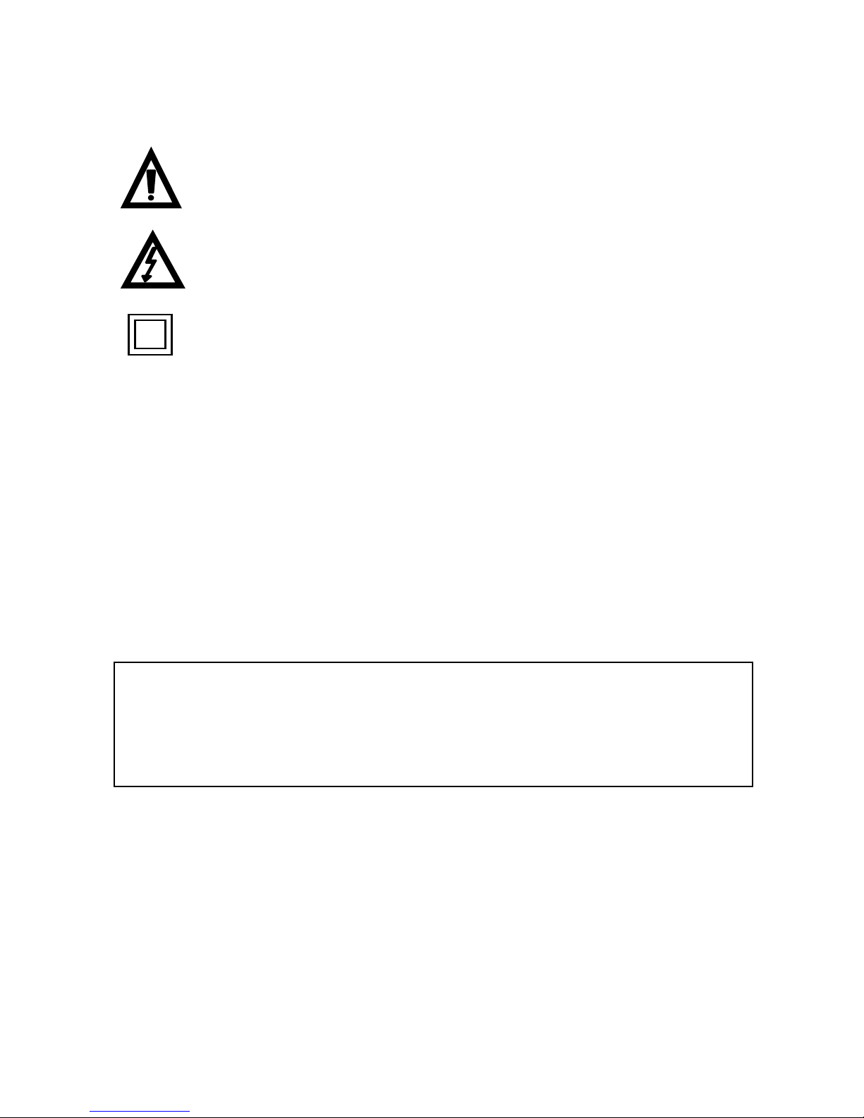
2.1 International Safety Symbols
This symbol, adjacent to another symbol or terminal, indicates the user must refer to the manual for further information.
This symbol, adjacent to a terminal, indicates that, under
normal use, hazardous voltages may be present
Double insulation
3 Preparation of the meter for operation
Having purchased the meter examine completeness of the contents of the package.
Before measurements commence, it is necessary to realise the
following actions:
• Make sure the conditions of the batteries or accumulators per-
mit to realise measurements,
• Make sure the casing of the meter and the insulation of the test
leads are not damaged.
WARNING:
Connection of inappropriate or damaged test leads constitutes a risk of an electric shock with a dangerous voltage.
Page 9
9
4 Functional description
4.1 Measurement sockets and elements of
selection of the measurement function
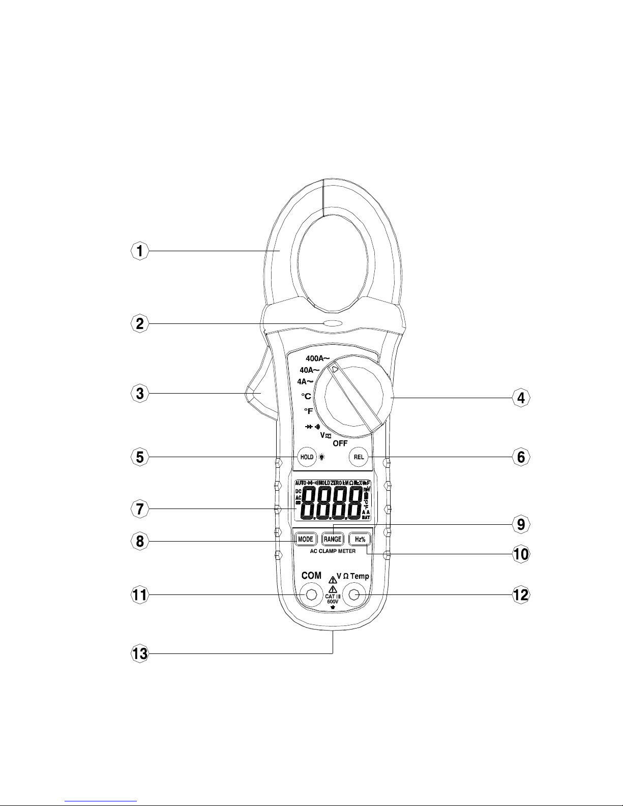
Illustration 1. CMP-400
Ω
Page 10
10
4.1.1 Sockets
11 measurement socket V/Ω/TEMP
Measurement socket for the purpose of measurements of direct and alternative voltages resistance, frequency and temperature.
12 measurement socket COM
Measurement socket common for all the measurement functions except of current measurements (connection to the
mass of the device).
4.1.2 Elements of selection of the measurement function
1 current clamp
2 non-contact AC voltage indicator light
3 clamp trigger
4 rotational selector
Selection of function:
• OFF – meter off,
• V – direct and alternative voltage measurement,
• Ω
– resistance and continuity measurement and
diode testing,
• °F – Fahrenheit temperature measurement,
• °C – Celsius temperature measurement,
• 4A~ – alternative current measurement up to 4A,
• 40A~ – alternative current measurement up to 40A,
• 400A~ – alternative current measurement up to 400A.
5 HOLD button
• Data Hold function,
• Back Light function (after holding for 2s).
6 REL button
• Relative measurement function,
• Exit of relative measurement
7 LCD display
8 MODE button
• Changing of measurement mode
Page 11
11
9 RANGE button
• Manual range selection
10 Hz/% button
• Frequency/duty cycle selection
13 battery cover
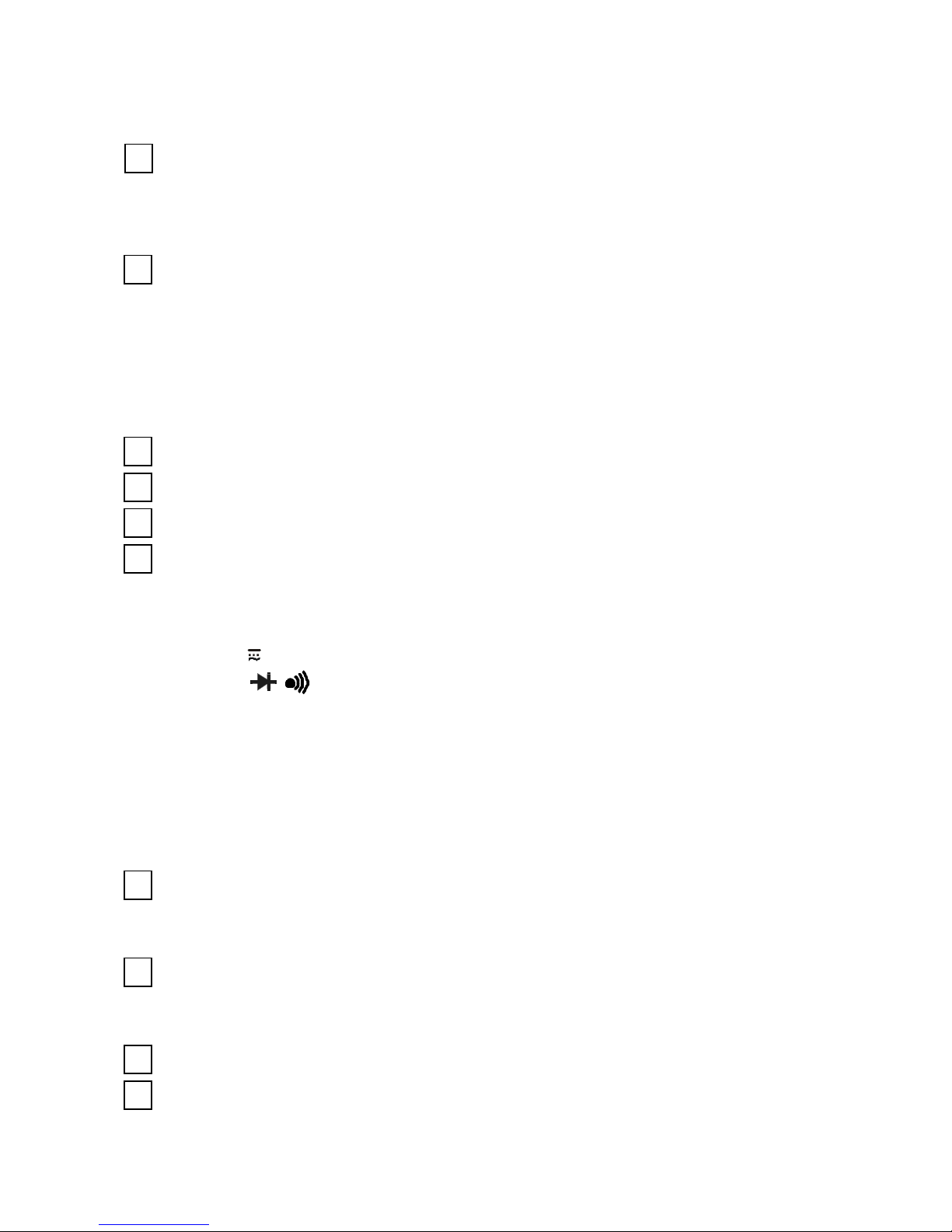
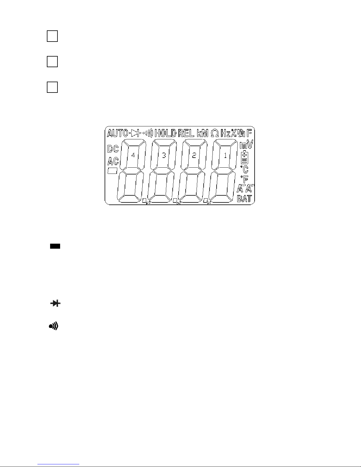
4.2 LCD display
Illustration 2. LCD display of the CMP-400 meter
– minus sign
AC, DC – AC (alternating current) and DC (direct currrent)
AUTO – AutoRange mode
– diode test mode
– continuity check mode
HOLD – Data Hold mode
ZERO – Relative Measurement mode
Hz % – frequency/duty cycle test mode
k, M, Ω, m, V, °C, °F, A – units of measure list
Page 12

12
+
_
_
_
– low battery indication
BAT – low battery indication (change battery)
4.3 Test leads
The manufacturer guarantees correct measurement indications
provided original test leads are used.
WARNING:
Connection of inadequate test leads constitutes a risk of
electric shock with a dangerous voltage or may be a cause of
measurement errors.
5 Measurements
It is recommended to get acquainted thoroughly with the contents of the present chapter since it describes the measurement
systems, the manner of realisation of measurements and the basic
principles of interpretation of the results.
5.1 AC current measurements
WARNING:
Do not take current readings on circuits where the maximum
current potential is not known. Do not exceed the maximum
allowable input range while measuring current.
WARNING:
Do not realise measurements if the battery compartment is
open.
Page 13

13
WARNING:
Do not commence measurements if the test leads are connected to the meter.
In order to realise a measurement of alternative current, it is
necessary to realise the following actions:
• Set the Function switch to the 400A~ or 40A~ or 4A~ range, if
the range of the measured is not known, select the highest
range first,
• open the clamp and place it on a single cable,
• read the result of the measurement on the display,
• move to the lower range if necessary.
Attention:
During measurements of the current make sure the clamp is
properly placed. Otherwise the results of the measurements
will not be exact. The most exact result we will get if the wire
is placed in the middle of clamp.
5.2 AC and DC voltage measurements
In order to realise a measurement of AC or DC voltage, it is
necessary to realise the following actions:
• set the function switch to the V position,
• select AC or DC with the MODE button,
• with the RANGE button set the measurement range manually
if necessary,
• connect the red test lead to socket V/Ω/TEMP and the black
one to socket COM,
• place the edges of the probes to the measurement points;
while measuring DC voltage place the red probe to the point of
higher potential,
• read the result of the measurement on the display,
Page 14
14
• having done the measurement disconnect the test leads from
the meter.
5.3 Resistance measurements
WARNING:
Measurements must not be realised in live circuits. Capacitors must be discharged.
WARNING:
Do not realise measurements if the battery compartment is
open.
In order to realise a measurement of the resistance it is neces-
sary to realise the following actions:
• place the rotational selector in the position Ω ,
• connect the red test lead to sockets V/Ω/TEMP and the black
one to sockets COM,
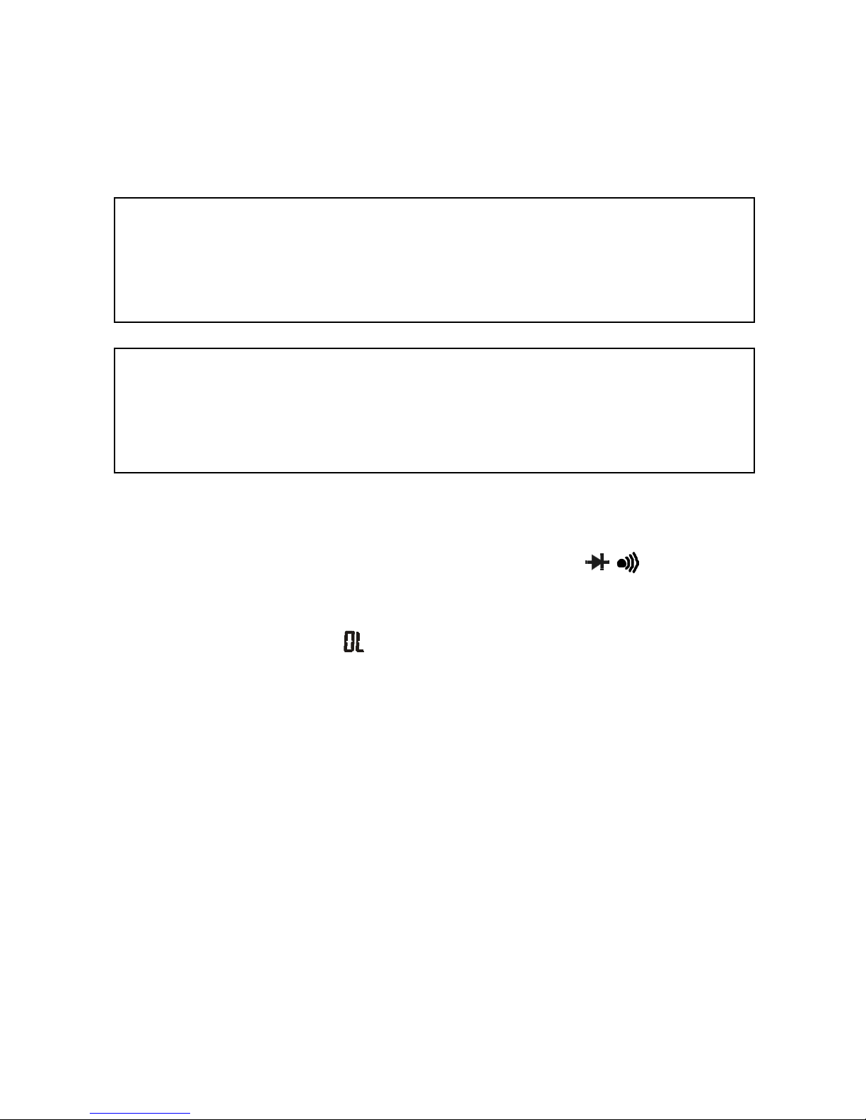
• make sure symbol
is displayed with open test leads, and in
the case of shorted terminals of the measurement probes the
display shows „0”,
• with the RANGE button set the measurement range manually
if necessary,
• touch the test probe tips across the circuit or component under
test; it is best to disconnect one side of the device under test
so the rest of the circuit will not interfere with the resistance
reading,
• read the result of the measurement on the display,
• having done the measurement disconnect the test leads from
the meter.
Page 15
15
5.4 Continuity Measurements
WARNING:
Measurements must not be realised in live circuits. Capacitors must be discharged.
WARNING:
Do not realise measurements if the battery compartment is
open.
In order to realise continuity test it is necessary to realise the
following actions:
• place the rotational selector in the position Ω ,
• connect the red test lead to sockets V/Ω/TEMP and the black
one to sockets COM,
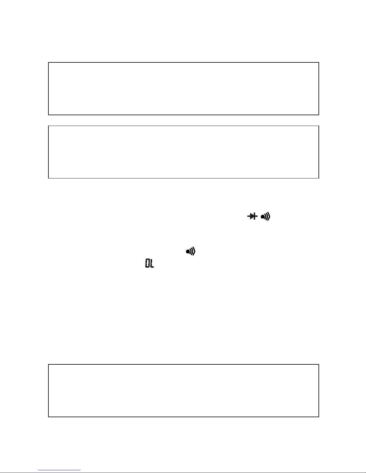
• press the MODE button until appears in the display,
• make sure symbol
is displayed with open test leads, and in
the case of shorted terminals of the measurement probes the
display shows „0”,
• touch the test probe tips to the circuit under test,
• read the result of the measurement on the display; if the re-
sistance is < 50Ω, a tone will sound,
• having done the test disconnect the test leads from the meter.
5.5 Diode Measurements
WARNING:
Measurements must not be realised in live circuits. Capacitors must be discharged.
Page 16
16
WARNING:
Do not realise measurements if the battery compartment is
open.
In order to realise continuity test it is necessary to realise the
following actions:
• place the rotational selector in the position Ω ,
• connect the red test lead to sockets V/Ω/TEMP and the black
one to sockets COM,
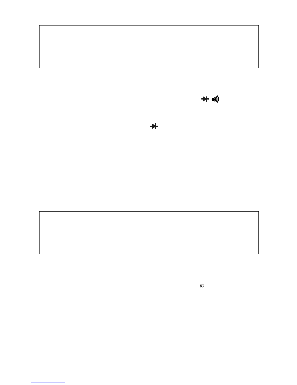
• press the MODE button until
appears on the display,
• touch the test probes to the diode under test - forward voltage
will indicate 0,4V to 0,7V, reverse voltage will indicate “OL”;
shorted devices will indicate near 0mV and an open device will
indicate “OL” in both polarities,
• having done the test disconnect the test leads from the meter.
5.6 Frequency or % duty cycle measure-
ments
WARNING:
Do not realise measurements if the battery compartment is
open.
In order to realise frequency or % duty cycle measurement it is
necessary to realise the following actions:
• place the rotational selector in the position V ,
• connect the red test lead to sockets V/Ω/TEMP and the black
one to sockets COM,
• select Hz or % duty with the Hz/% button,
• touch the test probe tips to the circuit under test,
• read the frequency on the display,
• having done the measurement disconnect the test leads from
the meter.
Page 17
17
5.7 Temperature measurements
WARNING:
Do not realise measurements if the battery compartment is
open.
WARNING:
To avoid electric shock, disconnect both test probes from
any source of voltage before making a temperature measurement.
WARNING:
To avoid electric shock, be sure the thermocouple has been
removed before changing to another measurement function.
In order to realise temperature measurement it is necessary to
realise the following actions:
• place the rotational selector in the position °C or °F,
• insert the temperature probe into the negative COM and the
V/Ω/TEMP terminals, making sure to observe the correct polarity,
• touch the temperature probe head to the part whose tempera-
ture you wish to measure, keep the probe touching the part
under test until the reading stabilizes (about 30 seconds),
• read the temperature in the display, the digital reading will in-
dicate the proper decimal point and value,
• having done the measurement disconnect the test leads from
the meter.
Page 18

18
5.8 Non-Contact AC Voltage Measurements
WARNING:
Risk of Electrocution. Before use, always test the voltage detector on a known live circuit to verify proper operation.
In order to realise the test it is necessary to realise the following
actions:
• touch the current clamp to the live conductor or insert into the
live side of the electrical outlet,
• if AC voltage is present, the detector light will illuminate.
Note:
The conductors in electrical cord sets are often twisted. For
best results, rub the probe tip along a length of the cord to
assure placing the tip in close proximity to the live conductor.
Note:
The detector is designed with high sensitivity. Static electricity or other sources of energy may randomly trip the sensor.
This is normal operation.
6 Special functions
6.1 Manual range selection
When the meter is first turned on, it automatically goes into AutoRanging. This automatically selects the best range for the measurements being made and is generally the best mode for most
measurements. For measurement situations requiring that a range
be manually selected, perform the following:
Page 19

19
• press the RANGE button - the “Auto Range” display indicator
will turn off,
• press the RANGE button to step through the available ranges
until you select the range you want,
• press and hold the RANGE button for 2 seconds to exit the
ManualRanging mode and return to AutoRanging.
6.2 Relative mode
Press REL button to enter the relative mode, the REL indicator
turns on, zero the display, and stores the displayed reading as a
reference value.
In the relative mode, the value shown on the LCD is always the
difference between the stored reference value and the present
reading. For example, if the reference value is 24,00V and the present reading is 12,50V, the display will indicate -11,50V. If the new
reading is the same as the reference value, the display will be zero.
Press the REL button again to exit the relative mode.
6.3 DATA HOLD Function and Backlight
display
To freeze the LCD meter reading, press the HOLD button. The
data hold button is located on the left side of the meter (top button).
While data hold is active, the HOLD display icon appears on the
LCD. Press the data hold button again to return to normal
operation.
Press and hold the HOLD button key for more than 2 seconds
to turn on the backlight. This will also activate the Data Hold
function. To release the Data Hold function and return the tester to
normal operation, press the HOLD button momentarily. To turn off
the backlight, press and hold the HOLD button for more than 2
seconds.
6.4 MODE button
The MODE button is used for DC/ACV or OHM/Diode/Continuity selection.
Page 20

20
7 Before you send the meter to be ser-
viced
Before sending the instrument to be repaired call the workshop,
since it is possible the meter is not damaged, and the problem has
occurred for some other reason.
Elimination of damage to the meter must be realised solely in
workshops authorised by the manufacturer.
The following table presents recommendations regarding proceeding in certain situations which may occur during operation of
the meter.
DESCRIPTION REASON SOLUTION
The meter does not
turn on.
Low batteries. Replace the batter-
ies. If the situation
does not change
send the meter for
repair.
Unintelligible and
randomly displayed
segments of the
LCD display.
Erroneous measurement after moving the meter from a
cold environment to
a warm place of high
humidity.
Lack of acclimatisation.
Do not perform
measurements until
the meter has
reached the temperature of the environment (approximately 30
minutes).
The test lead is
damaged.
The test lead is
broken or torn off
the terminal.
Replace the test
lead.
Page 21

21
8 Replacement of the batteries
The CMP-400 meter is supplied by means of one 9V battery. It
is recommended to use alkaline battery.
Attention:
When making measurements with a battery's mnemonic on,
one must take into account additional indefinite measurement uncertainty or unstable working of the meter.
WARNING:
Should the test leads be left in the sockets during replacement of the battery, there might be a risk of electric shock
with a dangerous voltage.
In order to replace the battery it is necessary to do the following:
• remove all the test leads from the measurement sockets and
place rotational selector in the position OFF,
• remove the one rear Phillips head screw,
• open the battery compartment,
•
replace the required one 9V battery
,
•
re-assemble the meter.
9 Cleaning and maintenance
The casing of the meter may be cleaned with a soft, damp cloth
using all-purpose detergents. Do not use any solvents or cleaning
agents which might scratch the casing (powders, pastes, etc.).
The electronic system of the meter does not require maintenance.
Page 22

22
10 Storage
In the case of storage of the device, the following recommendations must be observed:
• Disconnect all the test leads from the meter,
• Make sure the meter and its accessories are dry,
• In the case the meter is to be stored for a prolonged period of
time, the battery must be removed from the device.
11 Dismantling and utilization
Worn-out electric and electronic equipment should be gathered
selectively, i.e. it must not be placed with waste of another kind.
Worn-out electronic equipment should be sent to a collection
point in accordance with the law of worn-out electric and electronic
equipment.
Before the equipment is sent to a collection point, do not dismantle any elements.
Observe the local regulations concerning disposal of packages,
worn-out batteries and accumulators.
12 Attachments
12.1 Technical data
• “m.v.” means measured value of standard.
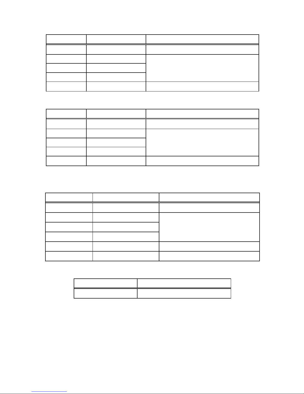
AC current measurement
Range Resolution Basic uncertainty
4,000A
0,001A
± (2,5% m.v. + 12 digits)
40,00A
0,01A
±
(2,5% m.v. + 8 digits)
400,0A
0,1A
±
(2,8% m.v. + 8 digits)
• frequency range 50...60Hz
Page 23
23
DC voltage measurement
Range Resolution Basic uncertainty
400,0mV 0,1mV
±
(0,8% m.v. + 2 digits)
4,000V 0,001V
± (1,5% m.v. + 2 digits)
40,00V 0,01V
400,0V 0,1V
600V 1V
±
(2% m.v. + 2 digits)
AC voltage measurement
Range Resolution Basic uncertainty
400,0mV 0,1mV
±
(1,5% m.v. + 30 digits)
4,000V 0,001V
± (1,8% m.v. + 8 digits)
40,00V 0,01V
400,0V 0,1V
600V 1V
±
(2,5% m.v. + 8 digits)
• frequency range 50...400Hz
Resistance measurement
Range Resolution Basic uncertainty
400,0Ω 0,1Ω
±
(1 % m.v. + 4 digits)
4,000kΩ 0,001kΩ
± (1,5 % m.v. + 2 digits) 40,00kΩ 0,01kΩ
400,0kΩ 0,1kΩ
4,000MΩ 0,001MΩ
±
(2,5 % m.v. + 3 digits)
40,00MΩ 0,01MΩ
±
(3,5 % m.v. + 5 digits)
Frequency measurement
Range Basic uncertainty
10Hz...10kHz
±
(1,5 % m.v. + 2 digits)
• sensitivity: 100V(<50Hz), 50V(50…400Hz); 5V(401Hz…10kHz)
Page 24
24
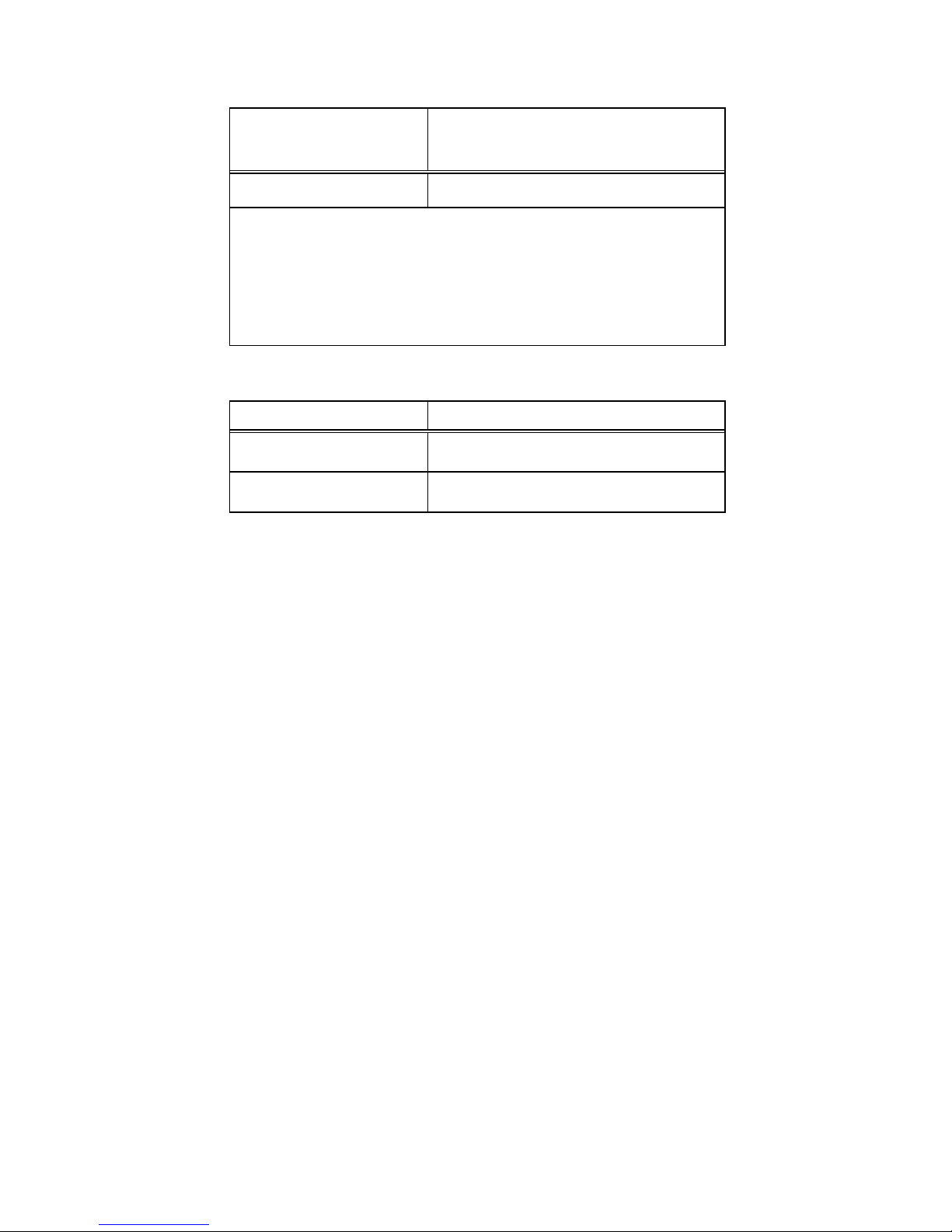
Duty Cycle
Range & Res-
olution
Basic Accuracy
10.0…94.9% unspecificated
Pulse width: 100µs…100ms,
Frequency: 30Hz…15kHz;
Sensitivity: 30…5kHz:10Vrms min.
5kHz…15kHz:40Vrms min.
Temperature measurement
Range Basic uncertainty *
-20.0…760,0°C ± (3% m.v. + 5°C)
-4.0…1400,0°F ± (3% m.v. + 9°F)
* probe (K type) accuracy not included
Other technical data
a) Measurement category in acc. with EN 61010-1 .............III 600V
b) Ingress protection in acc. with EN 60529 ............................ IP40
c) Pollution degree........................................................................ 2
d) Power supply ....................................................... one 9V battery
e) Clamp size.....................................Opening 30mm (1,2") approx
f) Diode test ................................................ I=0,3mA, U0=1,5V DC
g) Continuity test ......................... I<0,5mA, sound signal for R<50Ω
h) Overrange indication.............................................. OL displayed
i) Measurements rate .................................. 2 per second, nominal
j) Input impedance .............................................. 10MΩ (V AC/DC)
k) Display ...........................................................LCD, 4000 counts
l) Dimensions ..................................................... 197 x 70 x 40 mm
m) Weigh ................................................................................ 183 g
n) Operating temperature ........................... 5 to 40°C (41 to 104°F)
o) Storage temperature ............................ -20 to 60°C (-4 to 140°F)
p) Operating humidity ......... max 80% up to 31°C (87°F) decreasing
........................................................ linearly to 50% at 40°C (104°F)
q) Storage humidity ................................................................ <80%
r) Max. operating altitude .............................. 2000meters (7000ft.)
Page 25

25
s) Auto OFF ...................................................... approx. 30 minutes
t) Compliance with the requirements specified in the following
norms ...................................................................... EN 61010-1
............................................................................... EN 61010-2-032
u) Quality standard .......................................................... ISO 9001
12.2 Standard equipment
The standard set provided by the manufacturer includes the following components:
• The CMP-400 meter,
• Test leads (2 pieces),
• 9V battery,
• K-Type temperature probe,
• Carrying case
• Operating manual,
• Guarantee card.
Page 26

26
12.3 Manufacturer
The manufacturer of the device, which also provides guarantee
and post-guarantee service is the following company:
SONEL S. A.
ul. Wokulskiego 11
58-100 Świdnica
Tel: +48 74 858 38 60
Fax: +48 74 858 38 09
E-mail: [email protected]
Web page: www.sonel.pl
Note:
Service repairs must be realised solely by the manufacturer.
Made in China for SONEL S.A.
 Loading...