

Sondermann MAGSON MAS Type 4, MAGSON MAS Type 5, MAGSON MAS Series, MAGSON MAS Type 6 Operating Manual
Page 1
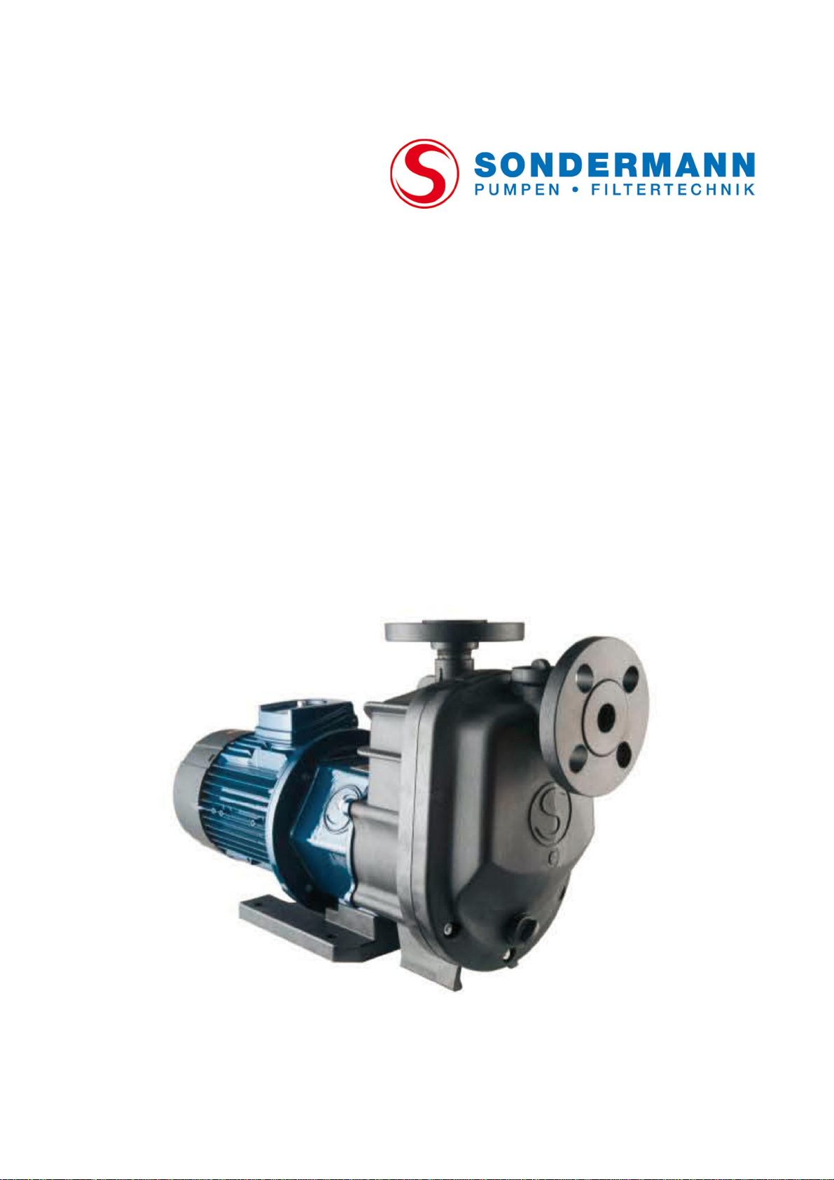
MAGSON magnetically coupled self-priming
centrifugal pumps
MAS types 4-6
Operating Manual
Page 2

Table of Contents
1. Declaration of conformity ......................................................... 5
2. Basic information ...................................................................... 7
2.1 Notes on the operating manual ................................................................. 7
2.2 Validity of data ......................................................................................... 7
2.3 Purpose ................................................................................................... 7
2.4 Use to the intended purpose ..................................................................... 7
2.5 Anticipated misuse .................................................................................... 8
2.6 Limits of use ............................................................................................ 8
2.7 Warranty and liability ................................................................................ 8
2.8 Contact details ......................................................................................... 8
3. Safety ........................................................................................ 9
3.1 Standards and directives ........................................................................... 9
3.2 Depiction of safety instructions ................................................................ 10
3.3 Symbols used ......................................................................................... 10
4. Technical Information............................................................. 11
4.1 General description ................................................................................. 11
4.2 Nameplate ............................................................................................. 11
4.3 Types MAGSON MAS ............................................................................... 11
4.4 Type codes and materials........................................................................ 12
4.5 Structure of MAGSON MAS ...................................................................... 14
5. Transport and temporary storage .......................................... 15
5.1 Safety instruction.................................................................................... 15
5.2 Transport ............................................................................................... 15
5.3 Temporary storage ................................................................................. 15
6. Installation .............................................................................. 15
6.1 Safety precautions .................................................................................. 15
6.2 Installation requirements ........................................................................ 15
2
6.3 Installation ............................................................................................. 16
6.3.1 Hose and pipe lines ...................................................................... 16
6.3.2 Suction line .................................................................................. 17
6.3.3 Discharge line .............................................................................. 17
Page 3

Centrifugal
pump
MAGSON
Issue
2019-01
6.3.4 Flange or threaded connections..................................................... 18
6.3.5 Electrical connection ..................................................................... 19
6.3.6 Controlli ng the direction of rotation ............................. .................. 20
7. Putting into operation ............................................................. 21
7.1 Safety precautions .................................................................................. 21
7.2 Preparatory work .................................................................................... 21
7.3 Putting into operation ........................................................................... .. 22
7.4 Possible malfunction when putting the pump into operation .......... ............ 22
8. Shut-down procedure ............................................................. 23
9. Service and maintenance ........................................................ 24
9.1 Safety precautions .................................................................................. 24
9.2 General information ................................................................................ 24
9.3 Preventive maintenance .......................................................................... 25
9.3.1 Overall pump ............................................................................... 25
9.3.2 Wearing parts .............................................................................. 25
9.3.3 Motor .......................................................................................... 26
9.3.4 Static O-ring seals ........................................................................ 26
9.4 Dismantling and replacing the motor ....................................................... 27
9.5 Dismantling the pump head .................................................................... 27
9.6 Disassembling the pump head ................................................................. 28
9.7 Assembling the pump ............................................................................. 29
10. Troubleshooting ...................................................................... 30
3
Page 4

Appendix ........................................................................................... 32
A) Technical data of MAS BG 4 - 6 ............................................................... 32
B) Exploded view MAS BG 4......................................................................... 35
C) Exploded view MAS BG 5......................................................................... 37
D) Exploded view MAS BG 6; 2.2 kW ............................................................ 39
E) Exploded view MAS BG 6; 3.0 – 4.0 kW .................................................. 41
F) Sicherheitshinweis Elektromotor .............................................................. 43
G) Declaration of decontamination ............................................................... 44
4
Page 5
Centrifugal
pump
MAGSON
Issue
2019-01
1. Declaration of conformity
Hausanschrift/Office: Postanschrift/Post address: Telefon/Phone: (02203) 9394-0 Bankverbindung/Bank Account: IBAN
August-Horch-Str. 2 Postfach/P.O.Box 92 01 01 Telefax/Fax: (02203) 9394-48 Stadtsparkasse Köln Kto. 30 02 425 (BLZ 370 501 98) DE94 3705 0198 0003 0024 25
D-51149 Köln D-51151 Köln Dresdner Bank AG, Köln Kto. 3 739 958 (BLZ 370 800 40) DE52 3708 0040 0373 9958 00
e-mail: [email protected] - Internet: http:// www.sondermann.com
Geschäftsführer/Managing Dir.: Klaus Hahn, HRA Köln 1739 - Sitz der Ges.: Köln - Registered Office: Köln - Ust-IdNr./V.A.T.-id.-No.: DE122907251
EC Declaration of Conformity
pursuant to the EC Machinery Directive 2006/42/EC, Annex II 1. A
Manufacturer:
S O N D E R M A N N Pumpen + Filter GmbH & Co. KG
August-Horch-Str. 2
D - 51149 Köln
Description and identification of the machine:
Product: Centrifugal pump
Type: MAGSON, series MA(S), MM, MPL, MPLN, MPT
Trade name: Magnetically coupled (self-priming) centrifugal pump,in horizontal alignment
Function: Pumps of the MAGSON series are designed to operate as centrifugal pumps
and are used to pump liquids.
It is explicitly stated that the machine corresponds to all relevant provisions of the following EC
Directives:
2006/42/EC Directive 2006/42/EC of the European Parliament and the European Council
from 17 May 2006 concerning machinery and the amendment to the 95/16/EC
Directive (new version) (1)
2014/30/EU Directive 2014/30/EU of the European Parliament and of the Council of 26
February 2014 on the harmonisation of the laws of the Member States relating
to electromagnetic compatibility (recast)
Source of applied harmonised standards according to Article 7 Paragraph 2:
Type A standard
EN ISO 12100:2010-11 Safety of machinery - General principles for design - Risk assessment and risk
reduction (ISO 12100:2010)
Type B standard EN ISO 13732-1:2008 Ergonomic of the thermal environment – Methods for the
assessment of human responses to contact with surfaces – Part 1: Hot
surfaces (ISO 13732-1:2008)
EN 1032:2003+A1:2008 Mechanical vibration – Testing of mobile machinery in order to determine the
vibration emission value
EN 60204-1:2006/AC:2010 Safety of machinery – Electrical equipment of machines – Part 1: General
requirements
5
Page 6

Type C standard
809:1998+A1:2009/AC:2010 Pumps and pump units for liquids – Common safety requirements
Standard
EN 61000-6-4:2007/A1:2011 Electromagnetic compatibility (EMC) - Part 6-4: Generic standards; Emission
standards for industrial environments
EN 61000-6-2:2005/AC:2005 Electromagnetic compatibility (EMC) - Part 6-2: Generic standards - Immunity
for industrial environments
EN 60034-1:2010/AC:2010 Rotating electrical machines – Part 1: Rating and performance
EN 60034-5/A1:2007-01 Rotating electrical machines – Part 5: Degrees of protection provided by the
integral design of rotating electrical machines (IP Code) – Classification
EN 60034-6:1993-11 Rotating electrical machines – Part 6: Methods of cooling (IC Code)
EN 60034-9/A1:2007-04 Rotating electrical machines – Part 9: Noise limits
Cologne, 08.01.2018
6
Page 7

Centrifugal
pump
MAGSON
Issue
2019-01
2. Basic information
2.1 Notes on the operating manual
This operating manual has been prepared to meet all product-specific and user-related
requirements of the law and of all relevant re gulat ions and rules, technical standards,
directives and agreements.
The manual includes important information on the funct ioning of M AGSON magnetically
coupled centrif ugal pumps and how to use, install, service and dispose of them.
In the following, the ma gnetica lly coupled centrifugal pumps are refe rred to a s “pump”.
Before putting the pump into operation, carefully rea d the operating manual and make
sure that it is always ready at hand to all users of the pump.
Complying with a ll i nstructions of this operati ng manual is an e ssentia l prerequ isite to
guarantee the safe opera tion and maint enance of t he pump.
Make sure that all operators and service technicians have fully read and understood the
manual before they sta rt working a t or with the p ump.
2.2 Validity of data
All technical data, dimensions and indications of weight etc. were valid at the day when
this manual went to pre ss. Specif ication s listed here may differ from the actual desig n of
the pump but will not modify any relevant informa tion in principle.
2.3 Purpose
MAGSON p umps are d esigned to function as centrifugal pumps delive ring fluids.
2.4 Use to the intended purpose
MAGSON pumps must only be used to deliver fluids of w atery viscosity without coarse
solids. So the fluids meant to be delivered are
# wat er and aqueous solutions,
# acid,
# base (brine),
# si milar fluids free of magnetizable me t al particles.
Do not use the pump to deliver
# inflammable or explosive fl uids,
# solid cont aining or a brasive fluids,
# fluids being used to process food because the pump has not been certified according
to FDA or EC 1935/2004 standards.
If you want to deliver solid containing or abrasive fluids, please contact the pump’s
manufacturer.
7
Page 8

2.5 Anticipated misuse
The pump is misu sed if
# it is used other than to the intended purpose;
# it is operated beyond its def ined limits;
# it is used to deliver inadmissible fluids like f luids cont aining magnetiz able metal
particles or coarse contaminants, for example.
2.6 Limits of use
Dimensional limits
For dimensions of the pump see æ Dimensioned drawings in the Appendix page 32 ff.
For technical data of the pump see æ Appendix page 30 ff.
Other limits
Ambient temperature 0 to 40°C for PP;
Pumps made of PP must not be operated in frost because PP will embrittle at
temperatures below 0°C.
-20 to ±40°C for ETFE
2.7 Warranty and liability
The pump must only be used to the intended purpose specified by this operating ma nual.
Inapp ropriate operation or insufficient service and maintenance will cancel the rig ht to all
warrant y claim s.
2.8 Contact details
SONDERMANN
Pumpen + Filter GmbH & Co. KG
August -Horch-Strasse 2
51149 Cologne (Porz), Germany
Phone: +49(0)2203 93940
Fax: +49(0)2203 939 448
[email protected]
www.sondermann-pumpen.de
8
Page 9
Centrifugal
pump
MAGSON
Issue
2019-01
3. Safety
Name
Contents
2006/42/EG
Directive 2006/42/EC of the European Parliamen
t and
2014/30/EU
Directive 2 014/30/EU o f the European Parliament and
Name
Contents
EN ISO 13732
-
1:2008
Ergonomics of the thermal environment
—
Method s for the
EN 1032:2003+A1:2008
Mecha nical vib ration
-
Testing of mobile machi nery
EN 61000
-6-
4:2007+
Electromagnetic comp atibility (EMC)
-
Part 6
-
4:
EN 61000
-6-
2:2005/
Electromagnetic comp atibility (EMC)
-
Part 6
-
2:
EN 809:1998+A1:2009 +
Pumps and pump unit s for liquid s
-
EN ISO 12100:2010
-11Safety of ma chinery
–
Genera l prin ciples for design
-
Risk
EN 60204
-
1:2006/
Safety of ma chinery
-
Electr ical equipment of machines
-
EN
60034
-
1:2010/
Rotating electrical machines
-
Part 1: Rating and
EN 60034
-
5/A1:2007
-01Rotating electrical machines
-
Part 5: Degrees of protection
EN 60034
-
6:1993
-11Rotating electrical machines
-
Part 6: Methods of
EN 60034
-
9/A1:2007
-04Rotating electrical machines
-
Part 9: Noise limits
3.1 Standards and directives
of the Council of 17 May 2006 on machi nery, and
amending Directive 95/16/ECG (recast) (1)
of the Council of 26 February 2014 on the harmonisation of
the laws of the Member States relating to
electromagnetic compatibility (recast)
Table 1: European Directives
assessment of human responses to contact with surfaces –
Part 1: Hot surfaces (ISO 13732-1:2008)
in order to d etermine t he vibration emission value
A1:2011
AC:2005
AC:2010
AC:2010
AC:2010
Generic standards - Emission standard for indust rial
environ ments
Generic standard s - Immunity for indu strial env ironment s
Common sa fety requi rements
assessment and risk reduction (ISO 12100:2010)
Part 1: General requi rements
performance
provided by int egral design of rotating electric al machines
(IP code) – Classificat ion
cooling (IC code)
Table 2: EN Standards
9
Page 10
3.2 Depiction of safety instructions
Symbol
Meaning
Cross
-
reference such as “see chapter xx“, “see page yy“
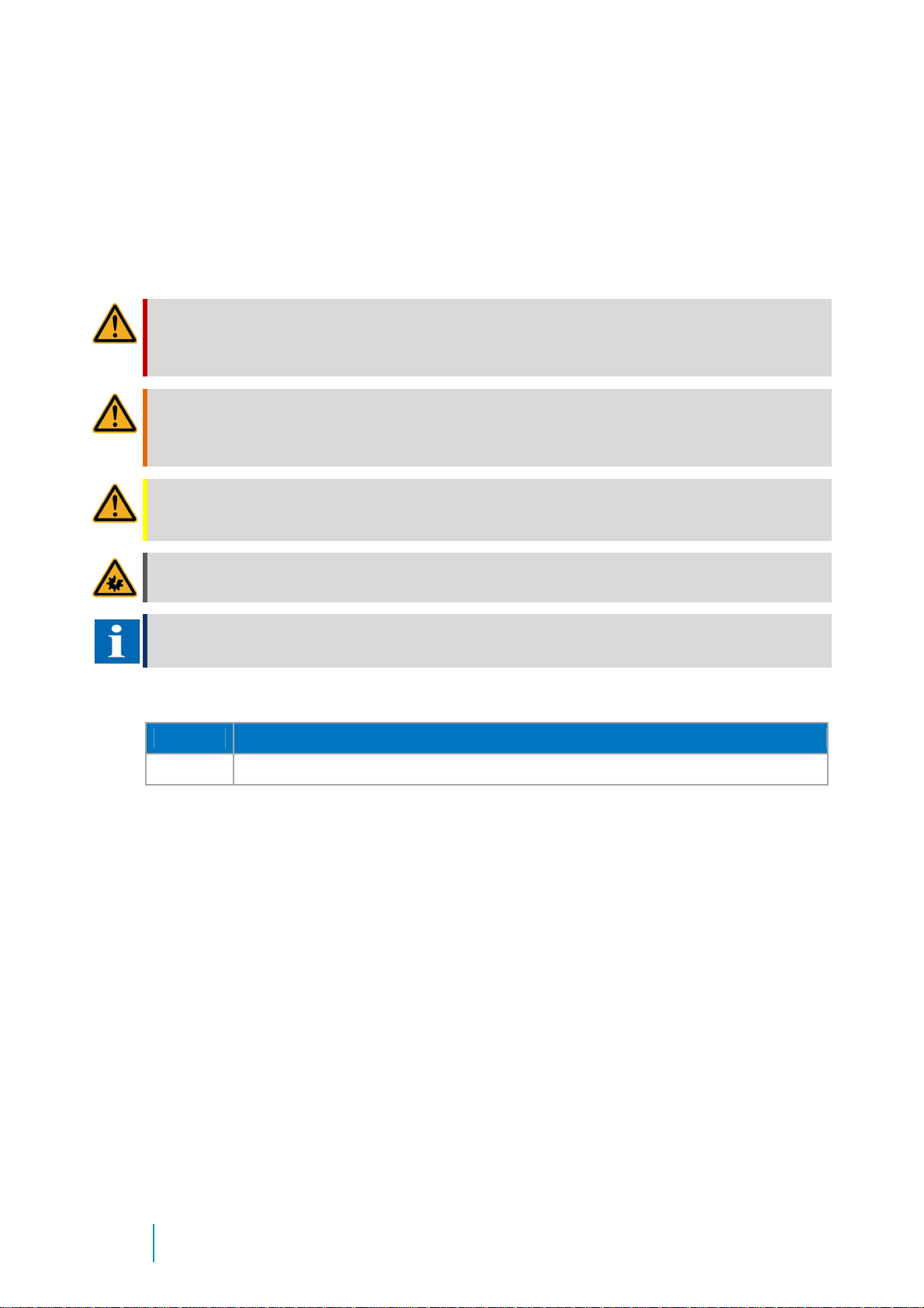
All safety instructions of this document are marked with symbols designed on the basis of
the SAFE principle. Each of them describes the kind and source of danger, possible
consequenc es and information on how to avert t hem.
DANGER
The symbol warns you of a potential accident resulting from ignoring safety or other instructions. The
accident will cause serious and maybe even mortal injuries or death when touching a high-voltage electrical
equipment, for example.
WARNING
The symbol warns you of a potential accident resulting from ignoring safety or other instructions. The
accident may cause seri ous and maybe even morta l injuries or death when touching a high-voltage electrical
equipment, for example.
CAUTION
The symbol warns you of a potential accident resulting from ignoring safety or other instructions. The
accident may cause slight injuries like burns, injuries of the skin and bruises, for example.
ATTENTION
The symbol warns you of a p otential material damage.
NOTE
The symbol indicates an important information.
3.3 Symbols used
æ
Table 3: Symbols used
10
Page 11
Centrifugal
pump
MAGSON
Issue
2019-01
4. Technical Information
4.1 General description
MAGSON type MAS magnetically co upled cent rifugal p umps are self-priming centrifugal
pumps made of plast ic and bui lt in horizo ntal singl e-stage mo noblock design. A magnetic
coupling connects the pump to the motor and transmits the power of the motor to the
impeller.
Pump housings, i mpellers, inner mag net sheaths and rea r casings are made of plastic.
The rear casing hermetically seals the fluid from the ambient atmosphere. Because of
magnetic power transmission, there is no need to mechanically seal the shaft. So, in
contrast to mechanically or gland sealed pumps, any leakage at the shaft is completely
impossible.
Pump type MAS has an integrated priming tan k whic h must b e filled with liquid b ef ore
initial startup.
4.2 Nameplate
The nameplate of the pump not only specifies its operating data but also its type and
serial number. Please indicate all these data when making an inquiry, reordering parts
and, in particular, when ordering spare parts. Data of the electric motor are given on a
separate rating plate. For further information, con tact your p ump's supplier or the
manufacturer.
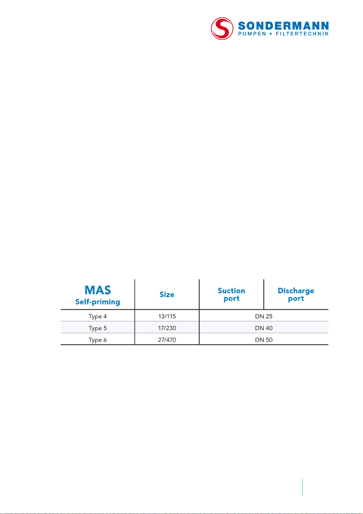
4.3 Types MAGSON MAS
11
Page 12
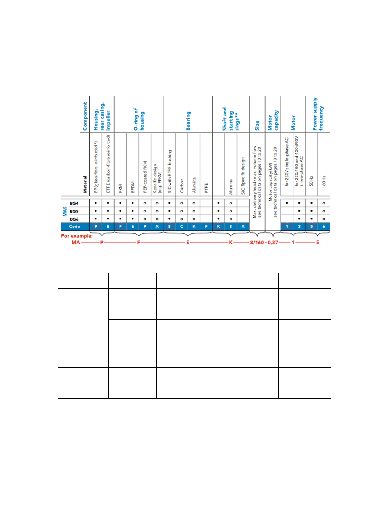
4.4 Type codes and materials
PPS
polyphenylene sulphide
-20to +100°C
The type code on the nameplate informs you about the p ump material s in contact with
fluid.
Overview of available materials being in contact with fluid:
Component Symbol Material Temperature
PP polypropylene 0 to 70°C
All components
in contact with
fluid
Seals
ETFE ethylene tetrafluoride ethylene -20 to +100°C
PTFE polytetrafluoroethylene -20 to +100°C
CFR-PTFE
SIC silicon carbide -20 to +100°C
Alumina aluminum oxide ceramic (99.7%) -20 to +100 °C
EPDM ethylene-propylene-diene rubber -20 to +100°C
FKM fluorinated rubber -20 to +100°C
FEP FEP-coated FKM -20 to +100°C
carbon fibre reinforced
polytetrafluoroethylene
-20 to +100°C
12
Page 13
Centrifugal
pump
MAGSON
Issue
2019-01
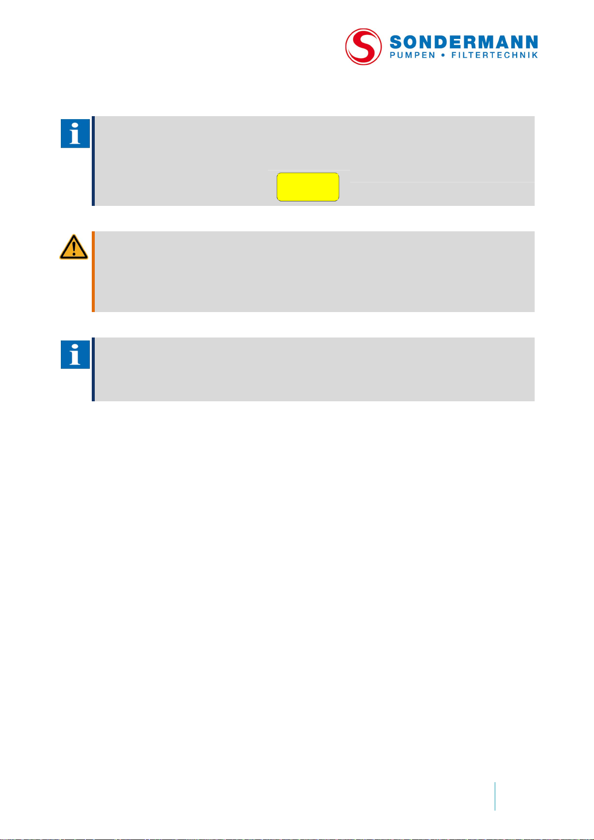
NOTE
Pump housings made of PP are of dark blue colour.
Pump housings made of ETFE are of black colour and marked with a yellow
sticker.
WARNING
Danger of chemical non-resistance of components
# Make sure that the materials u sed for making the pump are resistant to the fluid( s) delivered.
# Chemical non-resistance may result in leakage of fluid.
# Potential danger to the environment and health.
# In case of doubt, please con tact the pump’s manufacturer.
NOTE
For the chemical resistance of materials, please request the material resistance list of the pump’s
manufacturer.
ETFE
13
Page 14
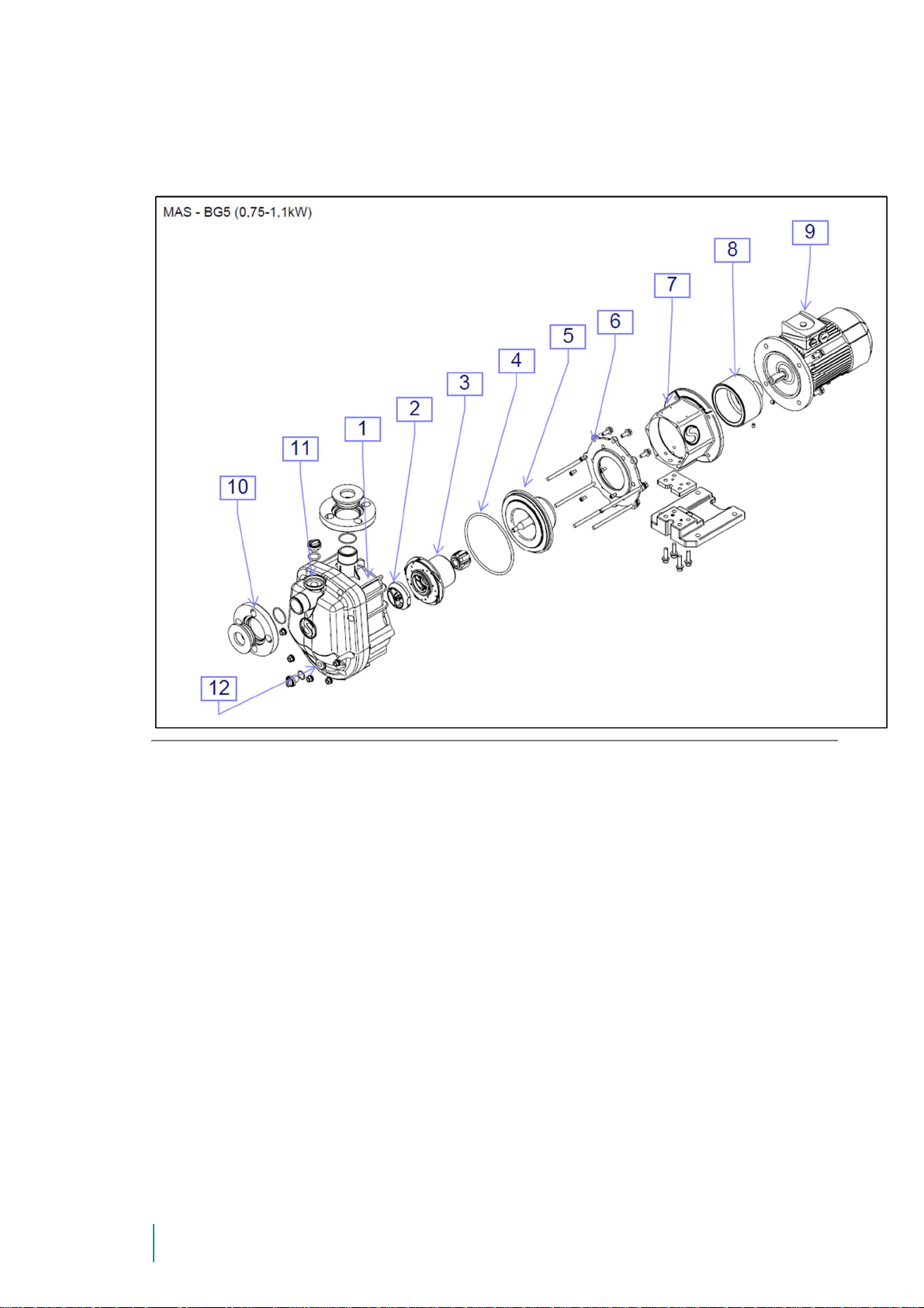
4.5 Structure of MAGSON MAS
Abb. 1: Structure of MAS BG 5
1 Pump casing 2 Shaft mounting
3 Impeller magnet 4 Casing-O-Ring
5 Rear casing with shaft 6 Mounting flange
7 Bracket with base 8 Outer magnet
9 Motor 10 Lose flange
11 Filling plug 12 Drain plug
Picture shows a MAS BG 5. Other sizes may differ,
please refer spare part drawing within appendix
14
Page 15
Centrifugal
pump
MAGSON
Issue
2019-01
5. Transport and temporary storage
5.1 Safety instruction
WARNING
Danger of getting jammed or bruised during transport of the pump
# Make sure to use lifting devices sui table to the wei ght of the pump.
# Do not remove the lifting device before you have put down the pump safel y.
5.2 Transport
1. Unpack the pump or unit upon receipt and che ck it for damage in trans it.
2. In case of damage in transit, make sure to have the carrier draw up and sign the
damage report document.
3. Make sure that the information of the namep late corre sponds with the specifications
and dimensions of the purchase order.
4. The packag ing material has to be disp osed of acco rding to lo cal regu lations.
5.3 Temporary storage
The pump must only be stored at a dry place free of frost. When storing the pump,
protect it against any contaminants getting in.
6. Installation
6.1 Safety precautions
WARNING
Danger of getting jammed or brui sed d uring installation of the pump
# If necessary, use lifting and holding d evices suitable to the size and weight of the pump.
# Make sure that all installation w o rk is done by competent and qualifi ed personnel only.
WARNING
Danger of being hit by falling components
# If necessary, use lifting and holding d evices suitable to the size and weight of the pump.
# Make sure that all installation w o rk is done by competent and qualifi ed personnel only.
6.2 Installation requirements
Install the pump at a place that allows you easy access at any time. The limit values of
Ambie nt temperature is as follow s: 0 to +40°C for pumps of PP;
-20 to +40°C for pumps of ETFE.
15
Page 16
6.3 Installation
1.
Install
the pump in a horizontal
position. For any other installation
position, plea se contact the
manufacturer.
2. Remove all covers and caps from
the flang es before i nstalling the
pump.
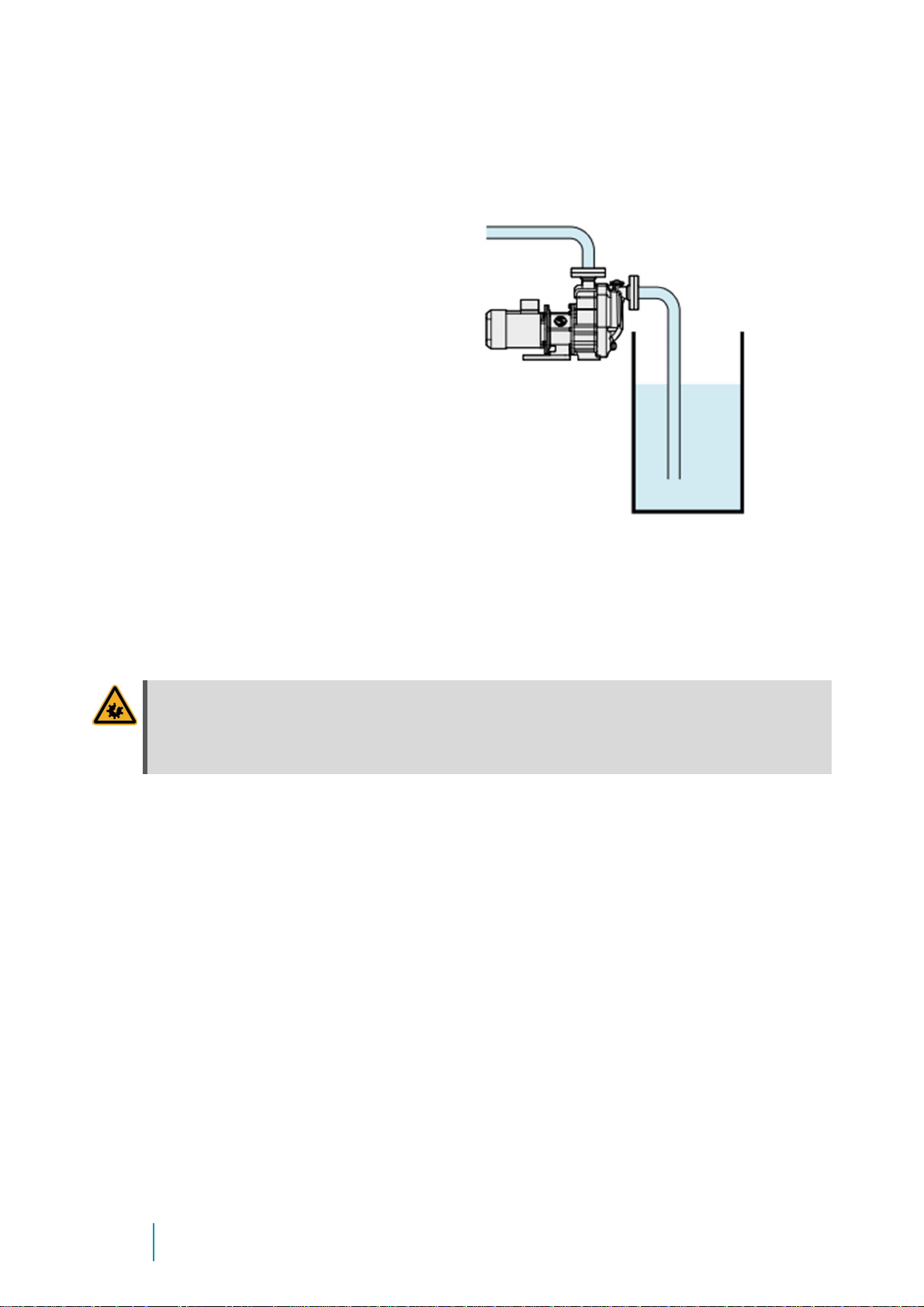
3. The Pump is self-p ri mi ng. There fore
it can b e placed above liquid level.
4. Max. suction height is 5 mWc
(Water @ 20°C)!
Maximum s uction height depends on the fluid to be handled. It may change due to:
# Fric tion lo sses in suc tion pipe
# Higher temperature of the fluid
# Higher density and/or visco sity
# Low er boiling t emperature
WARNING
Make sure all bolting’s at suction pipe are vacuum tight!
In case of leaky suction pipe the suction capacity of the pump can be reduced or pump
fails!
Make sure t hat the pump does not d raw in impurit ies when prim ing.
6.3.1 Hose and pipe lines
5. All pipe line d iameter s should be sufficiently la rge. The speed within the suction pipe
should be between 1 and 2m/s; speed within the discharge pipe should not exceed
3m/s. Pipe diameters have to be at least the size of the suction and discharge ports.
6. All suction and discharge p ipes to t he pump housing shou ld be free of tensi le stress.
7. If necessary, instal l expansion joint s at the p ipes to c ompensat e excess ive tension due
to the pipe’s thermal expansion.
8. Avoid bending radii of less tha n 1.5 times the nominal pipe size.
9. Also avoid sharp changes in diamet ers withi n the piping .
16
Page 17
Centrifugal
pump
MAGSON
Issue
2019-01
6.3.2 Suction line
ATTENTION
Risk of damaging the pump by cavitation
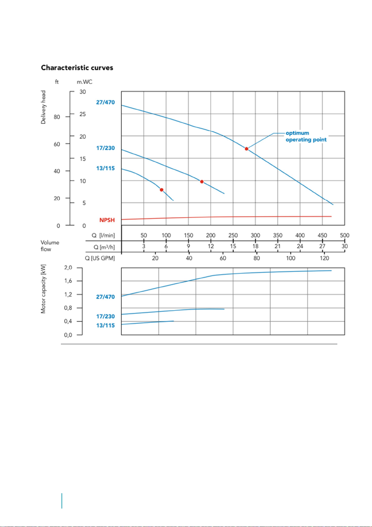
When installing the suction line, make sure to meet the NSPH value given in the æ Appendix page 32 foll.. If
the NPSH fal ls below this value, there will be cavitation result ing in running noise, drumming and vibration of
the pump.
We do not prov ide warranty for any damage to the pump caused by cavitation!
10. The suction pipe or hose should be made of a material that will not deform or distort
by vacuum or higher temperatures.
The suct ion line also should be as short as possibl e, its installati on preventing an y gas
accumu lation.
11. When d imensioning pip elines, fittings etc., ma ke sure t o keep t he flow resi stances as
low as possible.
12. Provide for a straight st eadying sectio n of at least 5 times t he nominal diameter
before the suction port.
13. Suction lines have to be vacuum-sealed because penetrating air causes malfunction
and may result in damag e to the p ump.
14. Make sure that the flow rate in the suction line installed does not exceed 1m/s.
15. Protect the pump against dry-r unning by installing adequate equipment (optionally
available).
16. For easy installation and removal of the pump, a shut-off valve (but no diaphragm
valve) should be built into t he suction line.
NOTE
Do not us e the shut- off valve of the sucti on line to adjust the de livery ra te!
6.3.3 Discharge line
Standard flow rat e of the discharge line is 3m /s.
Discha rge pipe should go straig ht upwards (approx. 500 mm) to avoid liqu id losses d uring
suction procedure.
We recommend installing a control element to adjust the flow rate of the discharge line.
ATTENTION
Damaging of the pump housing by pr essure jerks
Do not install any quick-acting stop valves to the pipelin es!
To measure working conditions , you bett er install a manome ter between the discharge
port of the pump and the throttle valve as well as a volume flow meter, if necessary.
17
Page 18
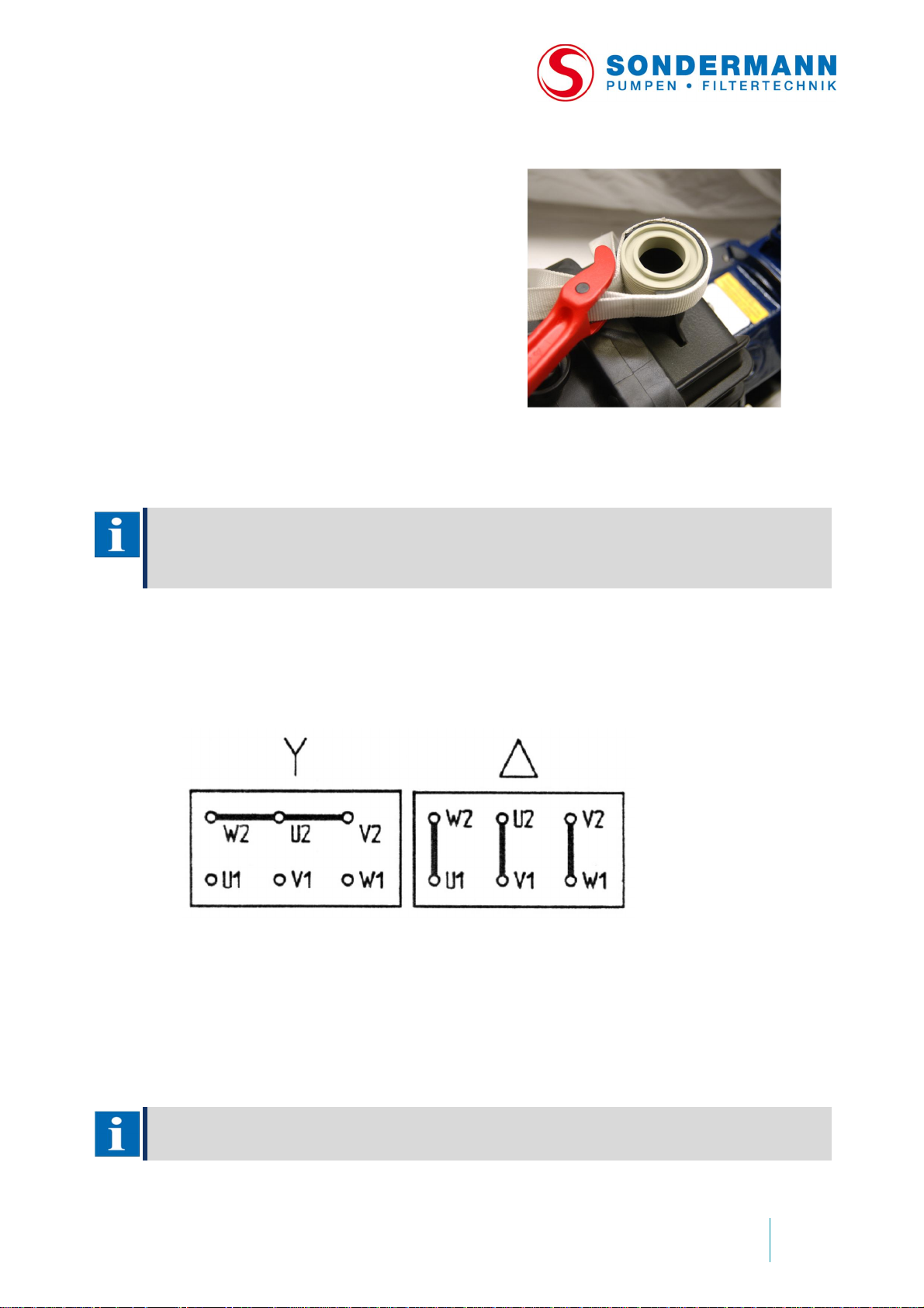
6.3.4 Flange or threaded connections
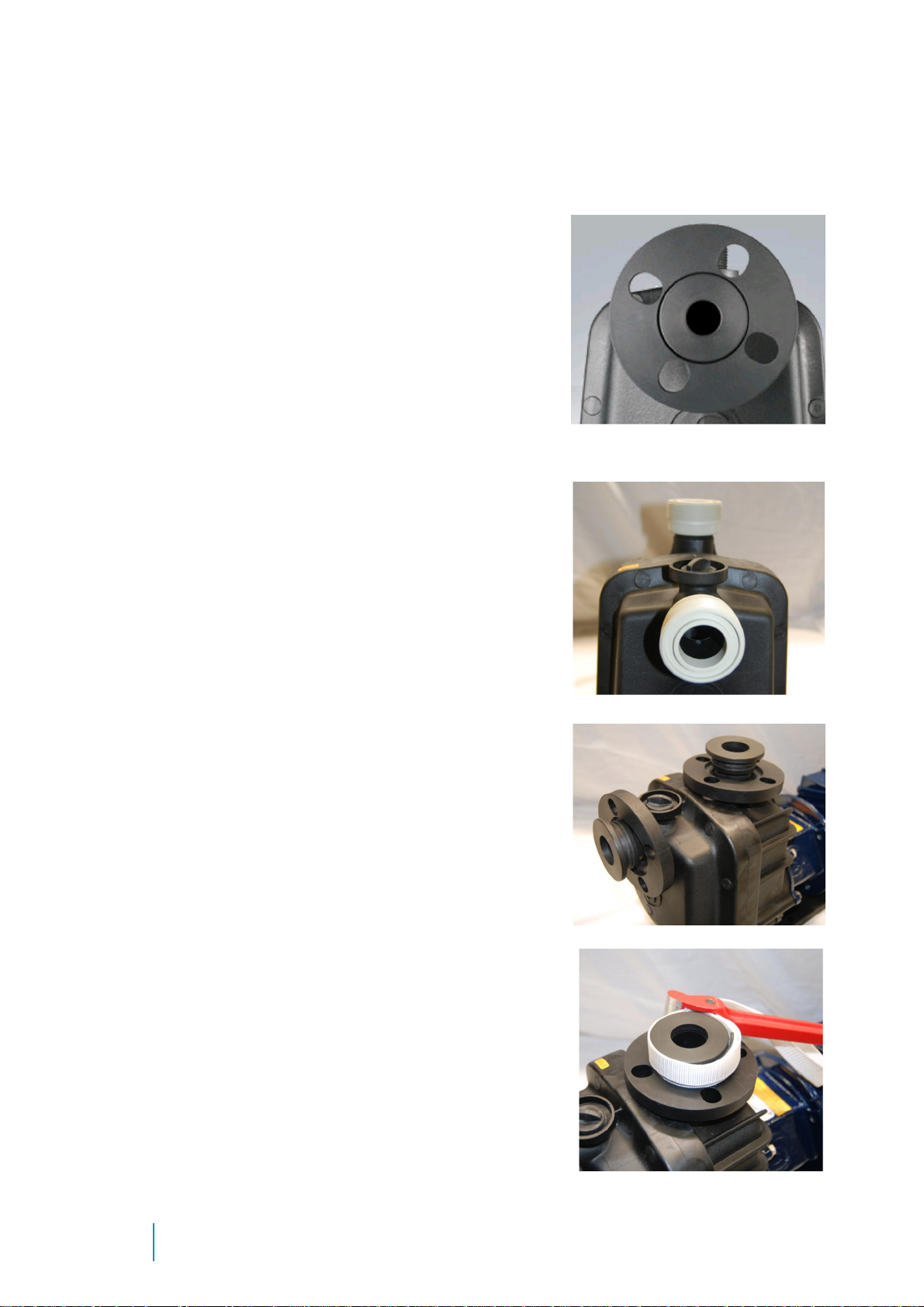
MAGSON MAS pumps of types BG4 to BG6 are
Replacin
g a flange by a threaded
equipped wit h slip-on flanges a s standard features.
The rotating flange allows you to easily connect the
pump wit hout considering the a ngular position of t he
mating flange.
Do not use hard material to seal the flange but
appropriate elastomer se als.
adapter
Alternatively yo u can use an in sert fitting
and spigot nut to connect the pump.
To do so, you have to replace the screwed
flange by the attached threaded adapter as
follows:
1. Take the slip-on flange off the flange
fixture using a rubber mallet.
2. Use a strap wrench to unscrew the
flange fixture. Take the O-ring off the
fixture and put it into the (inner thread)
of the threaded adapter.
18
Page 19
Centrifugal
pump
MAGSON
Issue
2019-01
3. Screw the threaded adapter to the
pump hou sing using t he strap wrench.
Make sure that the O-ring fits exactly
into the groove of the inner thread.
6.3.5 Electrical con nection
NOTE
Qualified personnel only are allowed to conne ct the pump to the electrical mains.
All electrical connections and the installation of additional protection devices has to be done in accordance
with the regulations of your local power supplier and the VDE Association of German Electrical Engineers.
Before working on the terminal box of the pump, the power supply must have been cut
off for at least 5 minutes.
17. Make sure that the power supply available corresponds to the data of the nameplate.
18. Connect t he motor according to the following schematic attached to the termina l box:
19. As standard features, all three-phase AC motors have PTC resistors to monitor the
winding temperature. To operate the pump with frequency converter, also connect
the PTC resistors.
20. All AC motors have a thermal sensor as standard feature which also has to be
connected.
21. Do not operate any AC motor without circuit-breaker!
NOTE
Please ask the manufacturer for additional motor protection devices.
19
Page 20
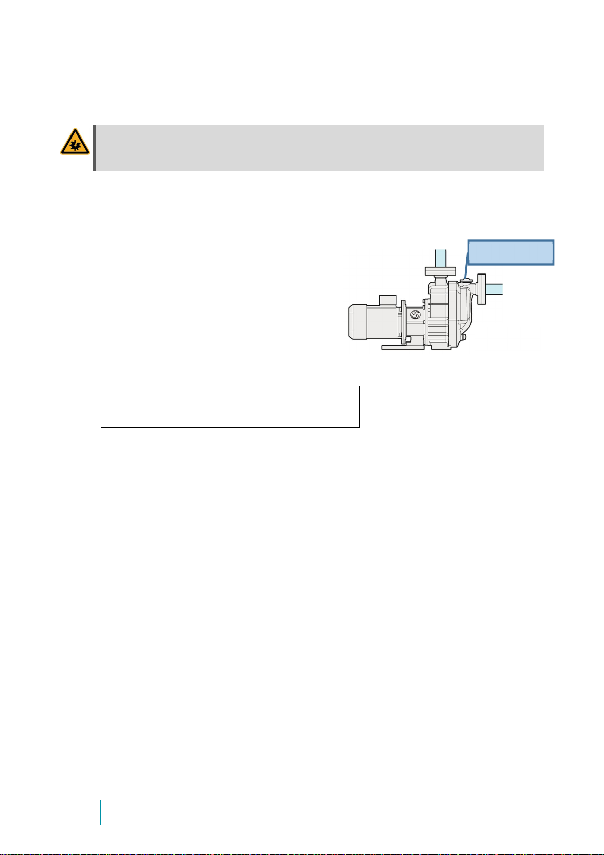
6.3.6 Controlling the direction of rotation
2.
Detach filling
plug at pump casing a
ndfill
Filling amount
:
MAS BG
-
4 13/115
2,7
Liter
MAS BG
-
5 17/230
2,7
Liter
MAS BG
-
6 27/470
3,6
Liter
ATTENTION
Dry-running w ill damage the pum p
Do not check the direction of rotation when there is no fluid in the pump!
1. Mind the direction of rotation indicated by an arrow on the pump. Before verifying it
after the installation, fill the pump housing and suction line with water or fluid (refer
item 2).
fluid into the integrated priming tank.
Attach filling plug properly afterwards.
Dry run of pump without fluid within
integrated priming tank has to be avoided!
Filling plug
3. Then switch on and immediately off the motor to check the direction of rotation.
To check whether the direction of rotation corresponds to the direction indicated by
the arrow, push a piece of soft material like paper or cable tie into the slots of the fan
cowl.
4. If necessary, exchange 2 phases at the terminal box to reverse the direction of
rotation.
20
Page 21
Centrifugal
pump
MAGSON
Issue
2019-01
7. Putting into operation
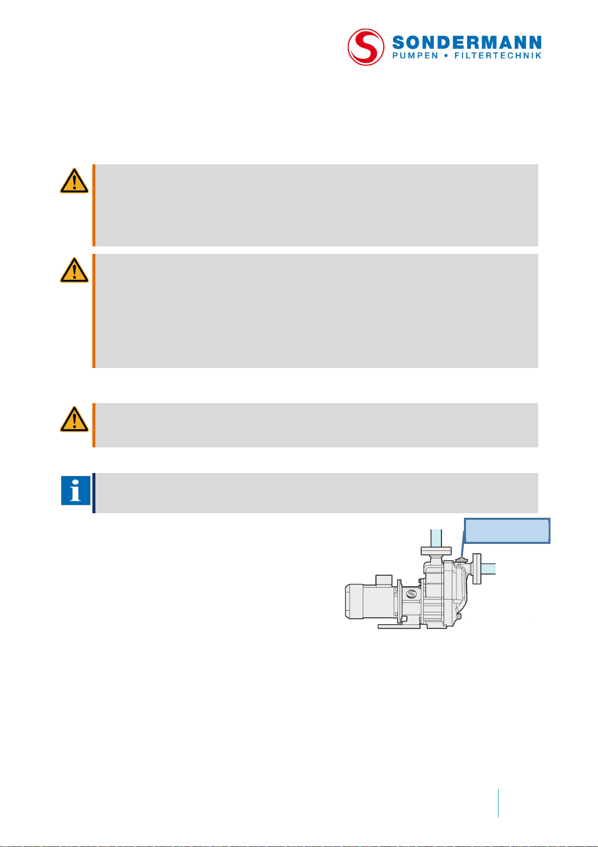
1.
Detach filling
plug at pump casing and fill
7.1 Safety precautions
WARNING
Danger of break ing during opera tion
Regularly check the pump for damages.
# If there is damage, the pump must not be operated!
# Replace wea ring parts at regular intervals.
# Do not operate the pump to other than the intende d purpose.
WARNING
Risk of electrical hazards when touching parts carrying voltage by fault
# Fasten all loose connections. Immediately replace defective cables.
# Always disconnect the power supply before doing any electrical work.
# Cables must ne ith er be jammed nor squeezed. When lay ing cables and conn ections make sure you
cannot trip over them and they won’t be damaged.
# Check all el ectrical equipment at regular intervals according to the locally valid regulations (like the
German DGUV accident pre vention regulation 3, for example).
# Only qualified and authorized personnel are allowed to do any work at the elec trical equipment.
7.2 Preparatory work
WARNING
Danger of injuries and intoxicat ion by fluid squirting out
# Always wea r personal protective equipment when workin g at the pump.
NOTE
We recommend installing dry-running protection dev ices such as flow monitors, c ontact manome ters,
differential p ressure switches or level contr ollers.
Filling plug
fluid into the integrated priming tank.
Attach filling plug properly afterwards.
Dry run of pump without fluid within
integrated priming tank has to be avoided!
2. Check necessary torques at all screws of the flanges. Take care of vacuum tight
suction pipe installation.
3. Open all valves at suct ion and discharge side completely.
21
Page 22

7.3 Putting into operation
1. Switch on the motor .
2. Pump starts to suck the air from suction pipe. This may take between
5 – 10 minutes depending size and length of suction pipe
As soon as the suction pipe is filled completely with fluid the norma l pump operatio n
starts.
3. Slowly open discharge valve to reach operation point. If no valve is installed at
discharge side the op eration conditio ns will be creat ed according t o plant installation
and pump performance curve.
ATTENTIO N
Overheating will damage the pump!
Do not run the pump with the discharge lin e closed for a longer period of t ime. This may result in heating up
the fluid inside the pump housing and damaging interior com ponents of the pump.
WARNING
Hazard of pressure
# Use a manometer at the disch arge line to check the system pressure and prevent it from going beyond
its limit specified in the technical data shee t (se e Appendix).
# If the syste m pressure is t oo high, the rear casing may burst releasi ng fluid.
# When press ure testing the piping, take into account the max imum system pressure, but do not test the
pump as well, if possible.
4. Check all screw joints and union pieces of the piping system for leakage.
5. Check the pump for vib ration. Ex cessive vibrat ion sugg ests cavit ation or f oreign
particles in the impeller (see æ chapter 10: Troubleshooting).
6. Make sure that the power input of the motor is less than or equal to the rated current
given on the motor’s nameplate.
If the power input is too high, reduce the delivery rate of the pump at the discharge
side or decrease the density of the fluid, if possible.
7.4 Possible malfunction when putting the pump into operation
If the motor circuit-breaker switches off the motor, proceed as follows:
7. Before switching on the motor again, check whether the impeller turns readily.
8. Make sure that the suction line a nd the pump housing are fil led with fluid.
9. Switch on the motor .
If the pump delivers for a short period of time only and then stops pumping, the magnetic
coupling has been overloa ded and disengaged. In this case , follow the instructions of æ
chapter 10: Troubleshooting (see page 30).
22
Page 23
Centrifugal
pump
MAGSON
Issue
2019-01
8. Shut-down procedure
1. Switch off the motor.
2. Close the shut-off valve s.
3. When some fluid remains within the pump , secure the shut-off valves to prevent an
accidental opening.
4. In case of crystallizing fluids, heat both the pump and the p iping. Protect freezing
fluids against frost.
5. If the pump will be out of operation for a longer period of time, thoroughly rinse it off
with a clean and neut ral liquid t o prevent remaining fluid from depositing within the
pump and at the sleeve bearings.
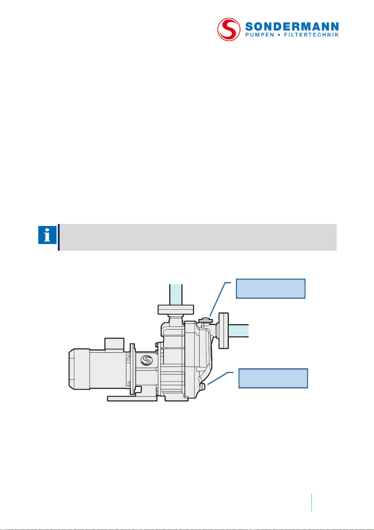
6. Open the drain plug an the integrated priming tank and rinse the fluid. Now open
filling p lug and clean the pump wit h fresh water.
7. In case the pump is shut down for repair or maintenance work, lock the driving unit
so that it cannot be sw itched on. Before dismant ling the p ump, shut off the s uction
and discha rge lines and empty the pump housi ng under monitored conditions.
NOTE
Secure all valves to prevent an accidental opening!
Always wear personal protective equipment!
Filling plug
Drain plug
23
Page 24
9. Service and maintenance
9.1 Safety precautions
WARNING
Risk of electrical hazards when touching parts carrying voltage by fault
# Only qualified an d authorized p ersonnel are allowed to work on motors at a stand still. The motors h ave
to be disconnected and secured against any accidental start.
# Strictly f o llow the instructions of the motor manufactur er.
# Comply with the safety rules for working on ele ctrical equipment.
WARNING
Hazardous magnetic fields
The magnetic fields resulting from the pump’s permanent-magnetic components will endanger persons with
cardiac p acema kers.
WARNING
Danger of break ing during opera tion
Regularly check the pump for damages.
# If there is damage, the pump must not be operated!
# Immediately replace the corrosi on p rotection if it’s damaged. Replace wea ring parts at regular int erv als.
# Do not operate the pump to other than the intende d purpose.
WARNING
Risk of electrical hazards when touching parts carrying voltage by fault
# Fasten all loose connections. Immediately replace defective cables.
# Always disconnect the power supply before doing any electrical work.
# Cables must ne ith er be jammed nor squeezed. When lay ing cables and conn ections make sure you
cannot trip over them and they won’t be damaged.
# Check all el ectrical equipment at regular intervals according to the locally valid regulations (like the
German DGUV accident pre vention regulation 3, for example).
# Only qualified and authorized personnel are allowed to do any work at the elec trical equipment.
WARNING
Risk of getting into contact wit h da ngerous substances
Before doing se rvice and maintenance work th at requires opening the pump, carefully clean the pump and
rinse it off with a neutral fluid.
WARNING
Danger of faulty installation and use of wrong or inadmissible spare parts
Components should be only replaced with genuine parts or spare parts authori zed by the manufactu rer.
WARNING
Risk of getting into contact with hot surfaces
Before working on drive units cool down the motors and actuators or wear heat-resistant protection gloves.
9.2 General information
This pump is designed for c ontinuous operation and does not require sp ecific
maintena nce. Nevertheless, we recommend doing the following p reventive ma intenance
work.
24
Page 25
Centrifugal
pump
MAGSON
Issue
2019-01
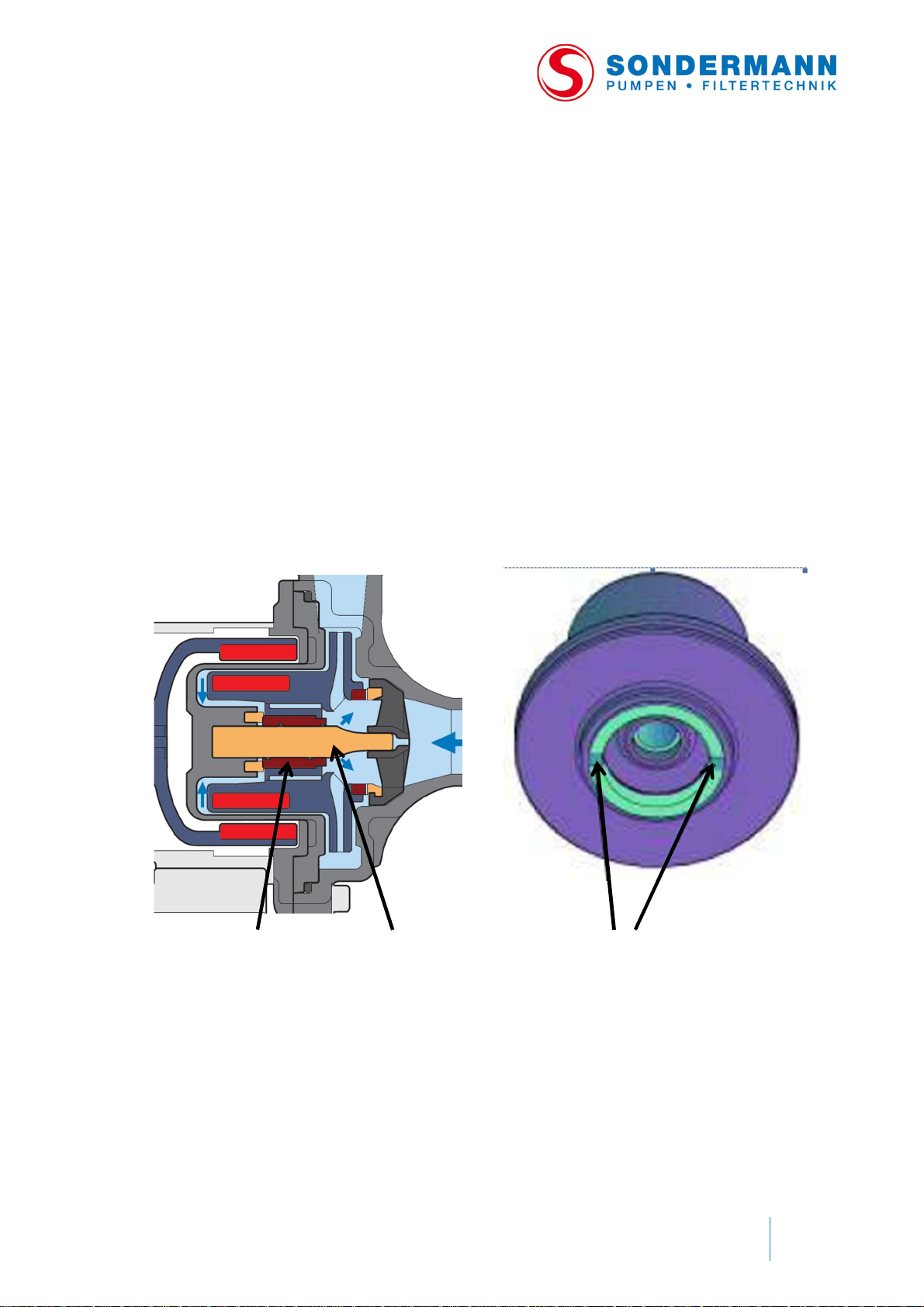
9.3 Preventive maint enance
1.
The sleeve bearing and centering shaft
2.
The start ing ring inside the impeller
9.3.1 Overall pump
Check the pump at reg ular interval s for
1. vibrations or unu sual noise,
2. a minimum volume flow of at least 5% of the maximum volume flow,
3. changes in normal op era ting cond itions, over heating or dry-running ,
4. leakage at the pump or piping,
5. cavitation in running,
6. open valves of the suction line and a clogged filter, if any.
9.3.2 Wearing parts
Though slee ve bearing , centering s haft and starting rings are d esigned for continuou s
operation, they are subject to wear and tear as well. So check the bearings for wear and
deposits at regular intervals, and replace them, if necessary.
should be replaced when they slack.
should be replaced once the grooves
are no longer vis ible.
25
Page 26

Impeller
All spare parts are available at Sonder mann Pumpen + Filter GmbH & Co. KG. See the Appendix for the spare
Replace the impeller magnet as soon as you see signs of wear or corrosion.
Starting rings
Check them for fissures, cracks and wear.
Rear casing
Check it inside and outside for signs of wear.
O-ring
Replac e the O-ring as soo n as the ela stomer s hows signs of chemical attack, fissures or
loss of elasticity.
NOTE
parts lists.
When delivering dirty, muddy or c rystallizing fluids, you should check and clean the pump
at shorter intervals.
9.3.3 Motor
8. Clean the fan cowl and cooling fins once a mont h.
9. Check the power input of the motor and compare it to the rated current given on the
nameplate.
9.3.4 Static O-ring seals
7. Visually in sp ect the seals for signs of wear at regula r i nterval s.
8. Replace the seal, if necessary.
NOTE
If not only wear parts are replaced, but also repair work has to be done, this should be performed by an
expert only. Im proper mainten ance wor k often re sults in superfluous ex tra costs.
26
Page 27
Centrifugal
pump
MAGSON
Issue
2019-01
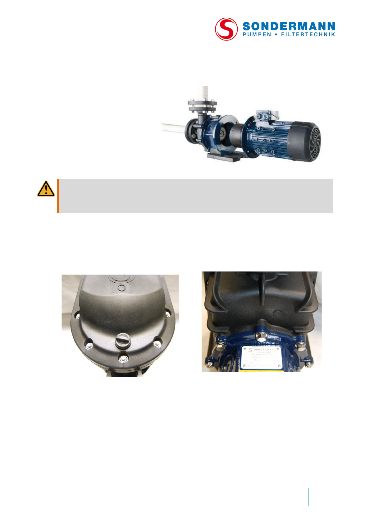
9.4 Dismantling and replacing the motor
The back pull
-
out design
2.
Loosen
of5nuts
atfront of pu mp
3.
Loosen
of 3 screws on top of backside
allows you to replace the
entire d rive unit wit hout
dismounting the p ump. So
neither the pump nor the
piping has to be drained.
Just loosen the 4 motor
screws and pull the motor off
the pump .
WARNING
Danger of stro ng magnetic forces and bruises
There are strong magnetic forces inside the pump between t he inn er magnet and the driving magnet. So pu ll
out the drive unit with a jerk being careful not to be bruised. Perhaps you will want to w ork in pairs.
9.5 Dismantling the pump head
1. Before dismantl ing the pump head, drain a nd careful ly rinse it.
casing.
of pump casing.
27
Page 28
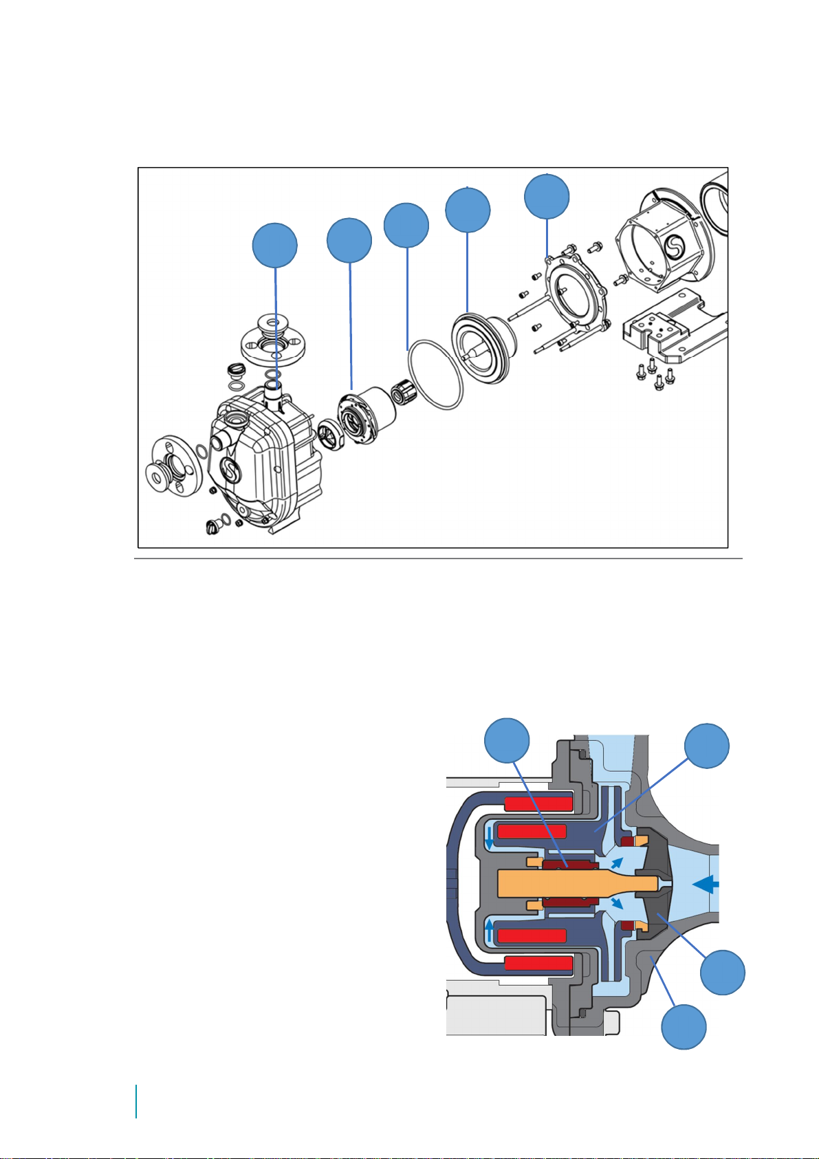
Dismantling the pump head
4.
Pull off the
complete
casing
(1)
7.
Take rear casing
(4)
off the bracket
Dismantling pump head – explosion drawing
5. Pull off the impeller magnet (2)
6. Remove casing O-Ring (3)
9.6 Disassembling the pump head
Press out the sleeve bearing B of the
impeller magnet C and replace it.
Press out the shaft mou nting D of the front
housing E and replace it.
Use appropriate tools to press out the
component s. If in doubt, ask the
manufacturer to replace them.
(5)
Caution: Strong magnetic forces
and risk of bruises!
28
Page 29
Centrifugal
pump
MAGSON
Issue
2019-01
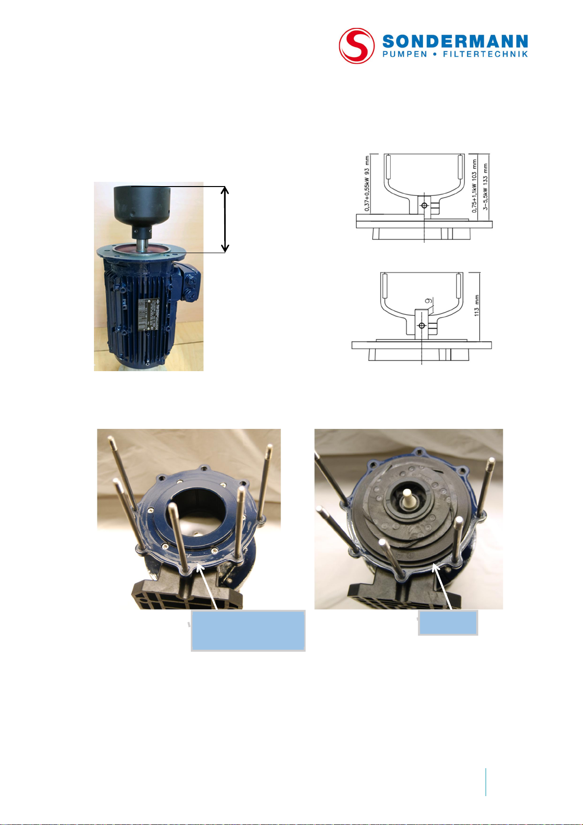
9.7 Assembling the pump
Place t he driving magnet on the motor
Screw mounting flange to bracket. Check if
Place rear casing with impeller magnet into
a
To reassemble t he dismantled pump, proc eed as follo ws:
shaft and align it.
Valid for motor with following power:
0,37; 0,55; 0,75; 1,1; 3,0; 4,0; 5,5 kW
Valid for motor with following power:
1,5; 2,2 kW
outer magnet can be moved easily.
Mark „V“ hast o be
placed at the bottom
bracket.
O-Ring
Caution: Strong magnetic forces and
risk of bruises.
Place O-Ring at rear casing
29
Page 30

10. Troubleshooting
Malfunction
Cause
Elimination
The pump does not start
The impeller jams.
Check bot h the impelle r and
The magnetic coupling
The impeller jams.
Open the pump head t o
There is a loud flow noise.
Wrong direction of
Correct the motor’s direction
There is air in the
Deaerate the piping and the
Since the p ump is non
-
Fill the suc tion line and
The delivery rate is too
Wrong direction of
Correct the direction of
The suctio n and/or
Clear the line, open the valves.
Cavitation.
Increase the NPSH of the
There is air in the pump.
Check the suc tion line and seal
No voltage. Check the voltage.
when being switched on.
the fan blade of the motor for
easy movement.
disengages.
There is a loud drumming
flow noise.
The starting delivery rate is
insufficient.
The relative density
and/or viscosity of the
fluid are too high.
The pump was switched
off, then swit ched on
again before the rotor
stopped completely.
Cavitation. Reduce the delivery rate of the
rotation.
suction li ne or pump
housing .
Reduce the delivery rate; use
a stronger magnetic coupling
and a more powerful motor.
Reduce the impeller diameter.
Make sure that the rotor has
stopped completely before you
switch o n the pump again.
eliminat e the obst ruction.
discharge line. Increase the
suction line diameter. Cool
down the fluid. Incr ease the
NPSH of the system.
of rotation.
housing .
30
low.
self-pri ming, both the
suction li ne and the
pump hou sing must be
filled with fluid .
rotation.
discharge line is
clogged.
housing with fluid
rotation.
system, see Ca vitatio n above.
it.
Page 31
Centrifugal
pump
MAGSON
Issue
2019-01
Malfunction
Cause
Elimination
The deliv
ery rate is too
high.
Pump losses are less
Reduce the flow rate of the
Unusual mecha n ical
Damaged bearing of the
Take the mo tor off the pump
Foreign p article in the
Open the pump head to check
The pump head bearing
Open the pump head to check
Leakage between pump
The pump housing is
Make an expert dismantle the
signif icant tha n
presumed.
discharge line.
Reduce the impeller diameter.
Use a frequency converter to
adjust the motor speed.
running noise.
and motor.
motor.
pump head.
overheat s when running
dry or hot.
damaged.
and check the motor b earings.
it.
it. Replace the sleeve bearing,
if necessary.
pump and eliminate the fault.
The pump is damaged
becau se of solid s, dryrunning or
overheating*.
Table 4: Troubleshooting
*) Detailed information on overheating and dry-running
„Overheating“ means the excessive warming of the fluid resulting from a closed
discharge and/or suc t ion line. As the fluid cannot leave the pump, there is no exchange of
fluid. The fluid remains in the pump where it p ermanently circulates and heats up. This
excessive warming may cause considerable damage to the pump and its components.
To avoid an increase in temperature, the minimum flow rate must not fall
below 5% of the maximum delivery rate!
If a pump is „running dry“, there is either air in the pump cha mber or the pump is not
filled up with fluid. Being neither cooled nor lubricated, the sleeve bearings will overheat.
As a consequence, the p lastic mat erial of the pump will also o verheat result ing in a lea ky
rear casing out of which fluid will pass.
31
Page 32
Appendix
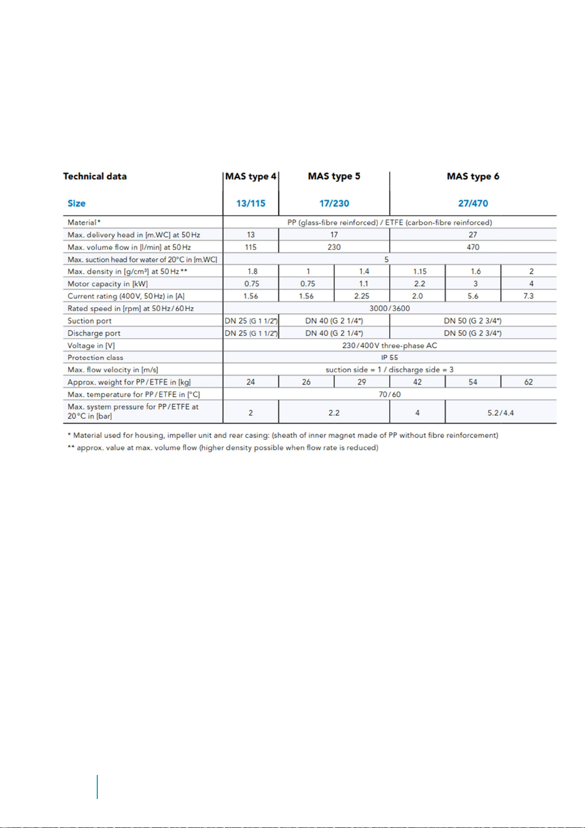
A)Technical data of MAS BG 4 - 6
Tab. 5: Te chnical data of MAS BG 4
32
Page 33
Centrifugal
pump
MAGSON
Issue
1| 201
9-01Appendix
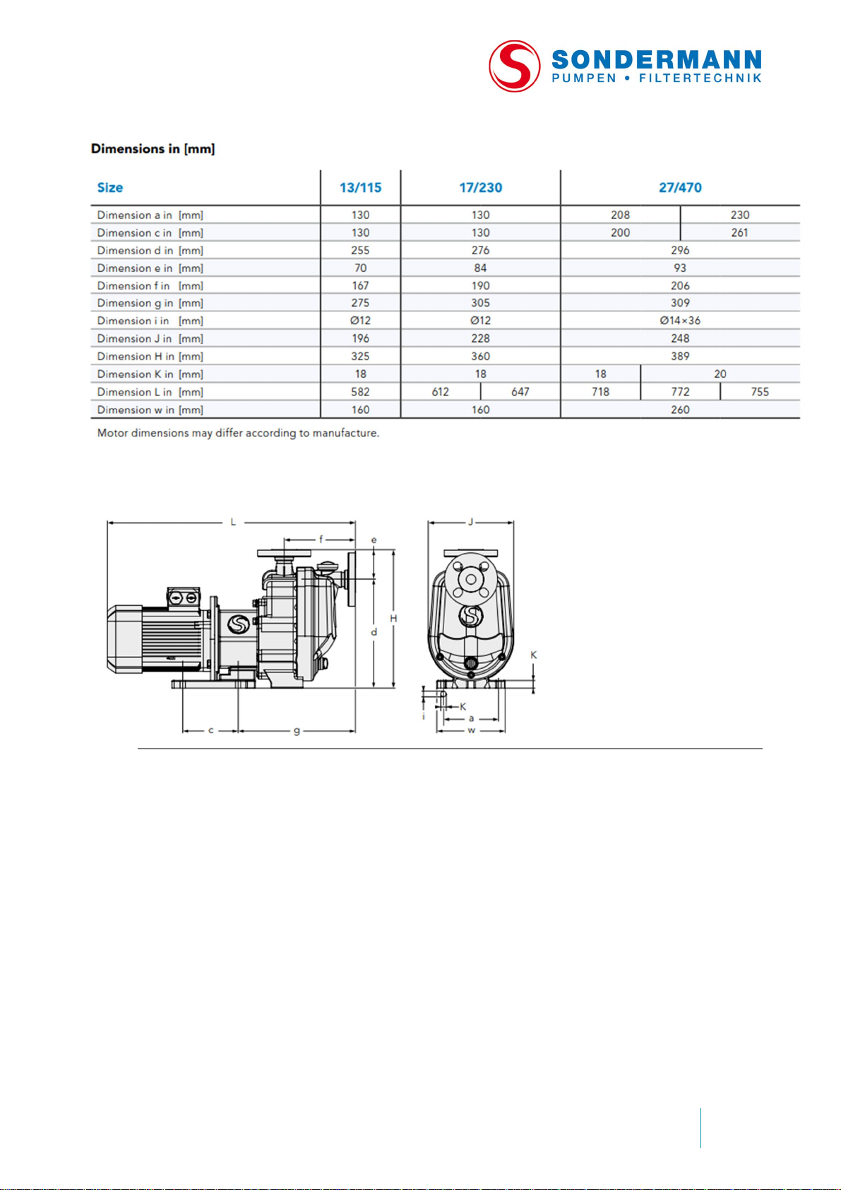
Abb. 2: Technical drawing of MAS BG 4
33
Page 34
34
Fig. 3: performance curves MAS, measured with water @ 20°C
Page 35
Centrifugal
pump
MAGSON
Issue
1| 201
9-01Appendix
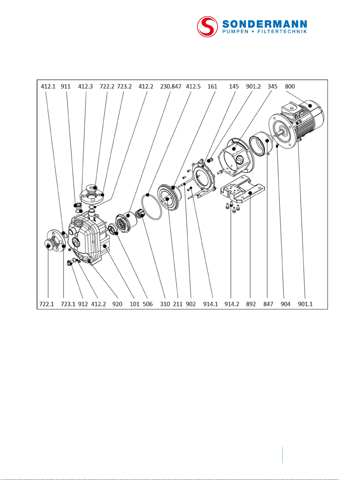
B)Exploded view MAS BG 4
35
Page 36

Spare parts list MAS BG 4
Part no.
Quantity
Article no.
Name
Material
1011Pump casing
see technical data sheet
1451Mounting flange
Cast iro n
1611Rear casing
see technica
l data sheet
2111Shaft
aluminum
oxide
230.847
1
Impeller magnet
see technical data sheet
3101Sleeve bearing
SiC / PTFE
314.1
1
Impeller starting ring
Graphit
e
314.2
1
Starting ring of rear casing
aluminum
oxide
3451
Bracket
GG
412.1
1O-
Ring of flange
see technical data sheet
412.2
1O-
Ring of flange
see technical data sheet
412.3
1O-
Ring Fil ling plug
see technical data sheet
412.4
1O-
Ring Draing plug
see technical data sheet
412.5
1O-
Ring of casing
see technical data sheet
5061Shaft mounting
see technical data sheet
722.1
1
Flange insert suction port
see technical data sheet
722.2
1
Flange insert discharge port
see technical data sheet
723.1
1
Slip-on flange suction port
see technical data
sheet
723.2
1
Slip-on flange discharge port
see technical data sheet
8001Elektr
ic
motor
Aluminum
8471Outer
magnet
Cast iro n
/ferrite8921Base plate
PP (
glass
fiber
901.1
4
Hexagon screw
M10 x 25
A2
901.2
3
Hexagon screw
M8 x
25
A2
9023Stud bolt
M5A2
9042Set screw
M8 x 10
A2
9111Filling plug
see technical data sheet
9121Drain plug
see technical data sheet
914.1
6
Allen screw
M6 x 12
A2
914.2
4
Allen screw
M8 x 25
A2
9205NutM6A2
ceramic 99.7%
ceramic 99.7%
reinforced)
36
Page 37
Centrifugal
pump
MAGSON
Issue
1| 201
9-01Appendix
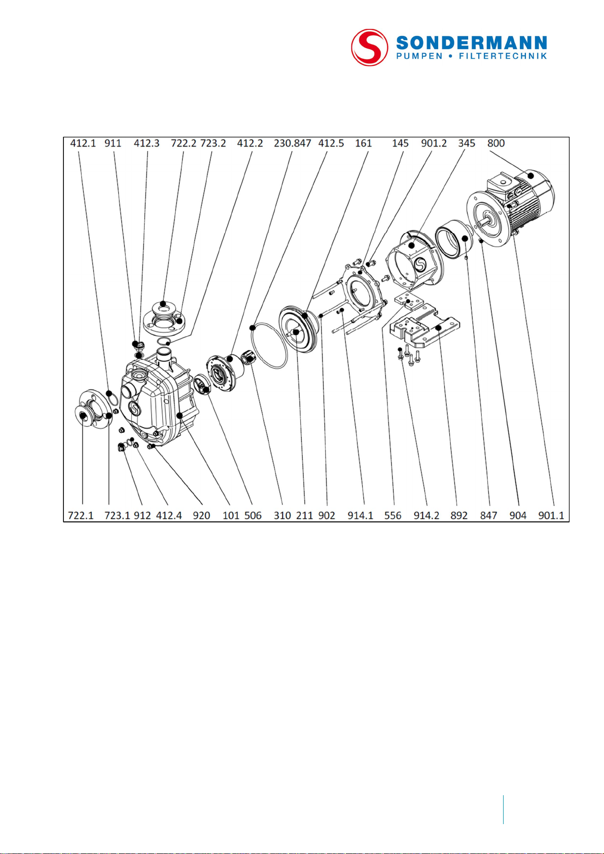
C)Exploded view MAS BG 5
37
Page 38

Spare parts list MAS BG 5
Part no.
Quantity
Article no.
Name
Material
1011Pump casing
see technical data sheet
1451Mounting flange
Cast iro n
1611Rear casing
see technical data sheet
2111Shaft
aluminum
oxide c eramic
230.8
471Impeller magnet
see technical data sheet
3101Sleeve bearing
SiC / PTFE
314.1
1
Impeller starting ring
Graphite
314.2
1
Starting ring of rear casing
aluminum
oxide c eramic
3451Bracket
GG
412.1
1O-
Ring of flange
see technical data
sheet
412.2
1O-
Ring of flange
see technical data sheet
412.3
1O-
Ring Fil ling plug
see technical data sheet
412.4
1O-
Ring Dra in
in
g plug
see technical data sheet
412.5
1O-
Ring of casing
see technical data sheet
5061Shaft mounting
see technica
l data sheet
722.1
1
Flange insert suction port
see technical data sheet
722.2
1
Flange insert discharge port
see technical data sheet
723.1
1
Slip-on flange suction port
see technical data sheet
723.2
1
Slip-on flange discharge port
see technical
data sheet
8001Electric
motor
Aluminum
8471Outer magnet
Cast iron / ferrite
8921Base plate
PP (glass
fiber
reinforced)
901.1
4
Hexagon screw M10 x 25
A2
901.2
3
Hexagon screw M8 x 25
A2
9023Stud bolt M5
A2
9042Set screw M8 x 10
A2
9111Filling plug
see technical data sheet
9121Drain plug
see technical data sheet
914.1
6
Allen screw M6 x 12
A2
914.2
4
Allen screw M8 x 25
A2
9205Nut M6
A2
99.7%
99.7%
38
Page 39
Centrifugal
pump
MAGSON
Issue
1| 201
9-01Appendix
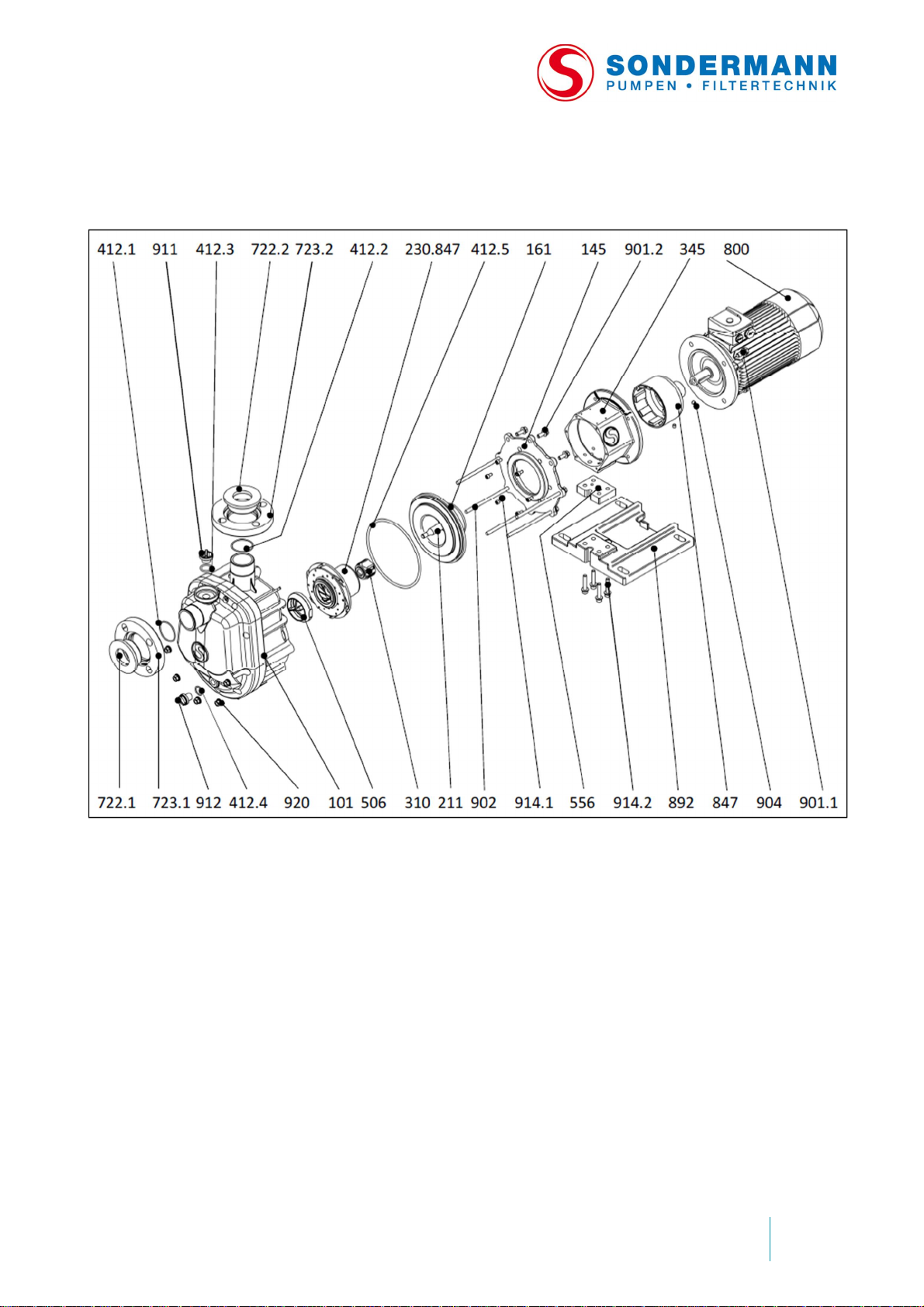
D)Exploded view MAS BG 6; 2.2 kW
39
Page 40
Spare parts list MAS B G 6; 2.2 kW
Part no.
Quantity
Article no.
Name
Material
1011Pump casing
see technical data sheet
1451Mounting flange
Cast iro n
1611Rear casing
see technical data sheet
2111Shaft
aluminum
oxide c eramic
230.847
1
Impeller magnet
see technical data sheet
3101Sleeve bearing
SiC / PTFE
314.1
1
Impeller starting ring
Graphite
314.2
1
Starting ring of rear casing
aluminum
oxide c eramic
3451Bracket
GG
412.1
1O-
Ring of flange
see technical data sheet
412.2
1O-
Ring of flange
see technical
data sheet
412.3
1O-
Ring Fil ling plug
see technical data sheet
412.4
1O-
Ring Dra in
in
g plug
see technical data sheet
412.5
1O-
Ring of casing
see technical data sheet
5061Shaft mounting
see technical data sheet
722.1
1
Flange insert suction p
ort
see technical data sheet
722.2
1
Flange insert discharge port
see technical data sheet
723.1
1
Slip-on flange suction port
see technical data sheet
723.2
1
Slip-on flange discharge port
see technical data sheet
8001Electric
motor
Aluminum
8471
Outer magnet
Cast iron / ferrite
8921Base plate
PP (glass
fiber
reinforced)
901.1
4
Hexagon screw M10 x 25
A2
901.2
3
Hexagon screw M8 x 25
A2
9023Stud bolt M5
A2
9042Set screw M8 x 10
A2
9111Filling plug
see technical data sheet
9121Drain plug
see technical data sheet
914.1
6
Allen screw M6 x 12
A2
914.2
4
Allen screw M8 x 25
A2
9205Nut M6
A2
99.7%
99.7%
40
Page 41
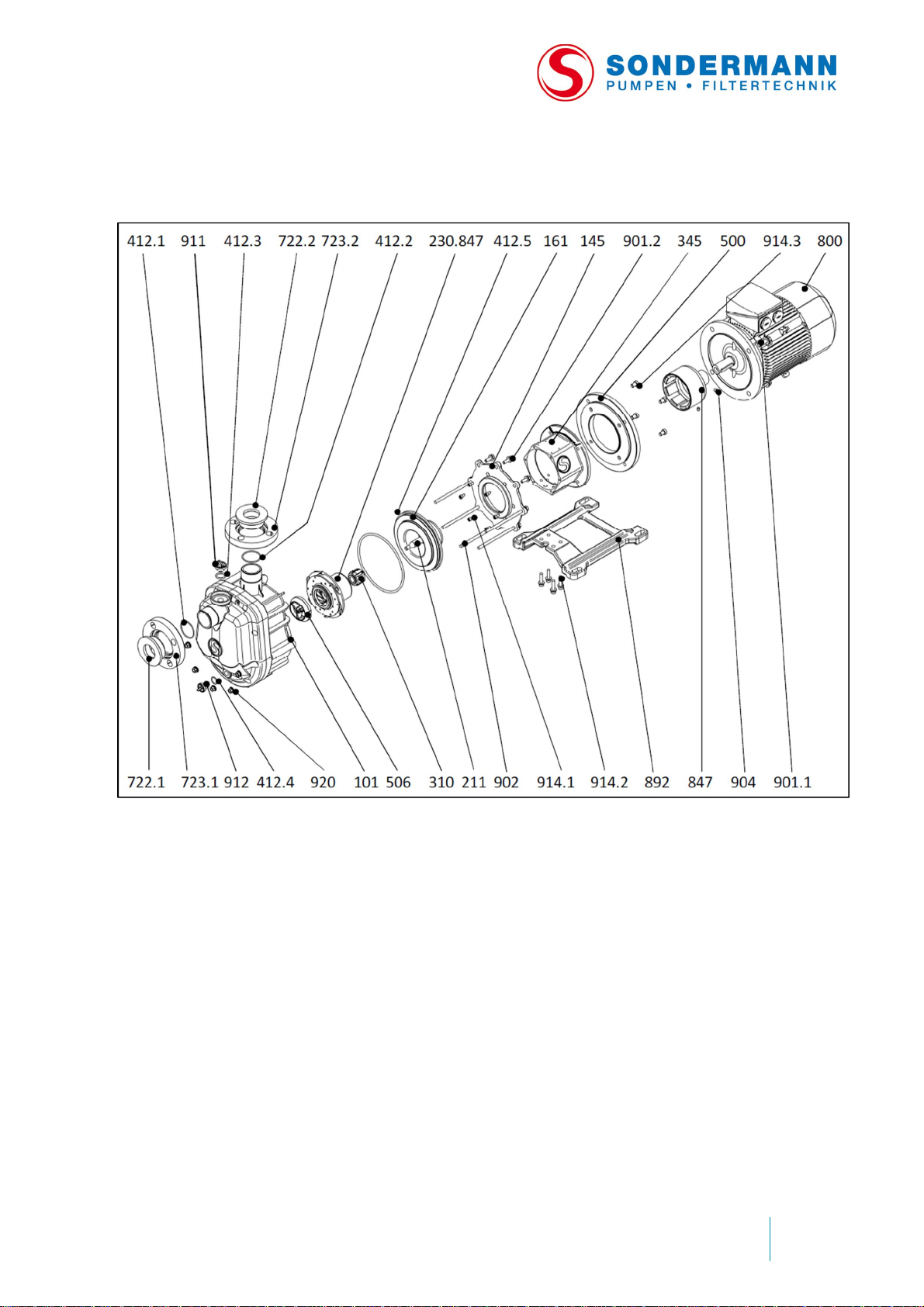
Centrifugal
pump
MAGSON
Issue
1| 201
9-01Appendix
E) Exploded view MAS BG 6; 3.0 – 4.0 kW
41
Page 42

Spare parts list MAS B G 6; 3.0 – 4.0 kW
Part no.
Quantity
Article no.
Name
Materia
l
1011Pump casing
see technical data sheet
1451Mounting flange
Cast iro n
1611Rear casing
see technical data sheet
2111Shaft
aluminum
oxide c eramic
230.847
1
Impeller magnet
see technical data sheet
3101Sleeve bearing
SiC / PTFE
314.1
1
Impeller starting ring
Graphite
314.2
1
Starting ring of rear casing
aluminum
oxide c eramic
3451Bracket
GG
412.1
1O-
Ring of flange
see technical data sheet
412.2
1O-
Ring of flange
see technical data sheet
412.3
1O-
Ring Fil li
ng plug
see technical data sheet
412.4
1O-
Ring Dra in
in
g plug
see technical data sheet
412.5
1O-
Ring of casing
see technical data sheet
5061Shaft mounting
see technical data sheet
722.1
1
Flange insert suction port
see technical data sheet
722.21
Flange insert discharge port
see technical data sheet
723.1
1
Slip-on flange suction port
see technical data sheet
723.2
1
Slip-on flange discharge port
see technical data sheet
8001Electric
motor
Aluminum
8471Outer magnet
Cast iron / ferr
ite
8921Base plate
PP (glass
fiber
reinforced)
901.1
4
Hexagon screw M12 x 30
A2
901.2
3
Hexagon screw M8 x 25
A2
9023Stud bolt M8
A2
9042Set screw M8 x 10
A2
9111Filling plug
see technical data sheet
9121Drain plug
see technical da
ta sheet
914.1
6
Allen screw M6 x 12
A2
914.2
4
Allen screw M8 x 30
A2
914.3
4
Allen screw M8 x 20
A2
9205Nut M8
A2
99.7%
99.7%
42
Page 43
Centrifugal
pump
MAGSON
Issue
1| 201
9-01Appendix
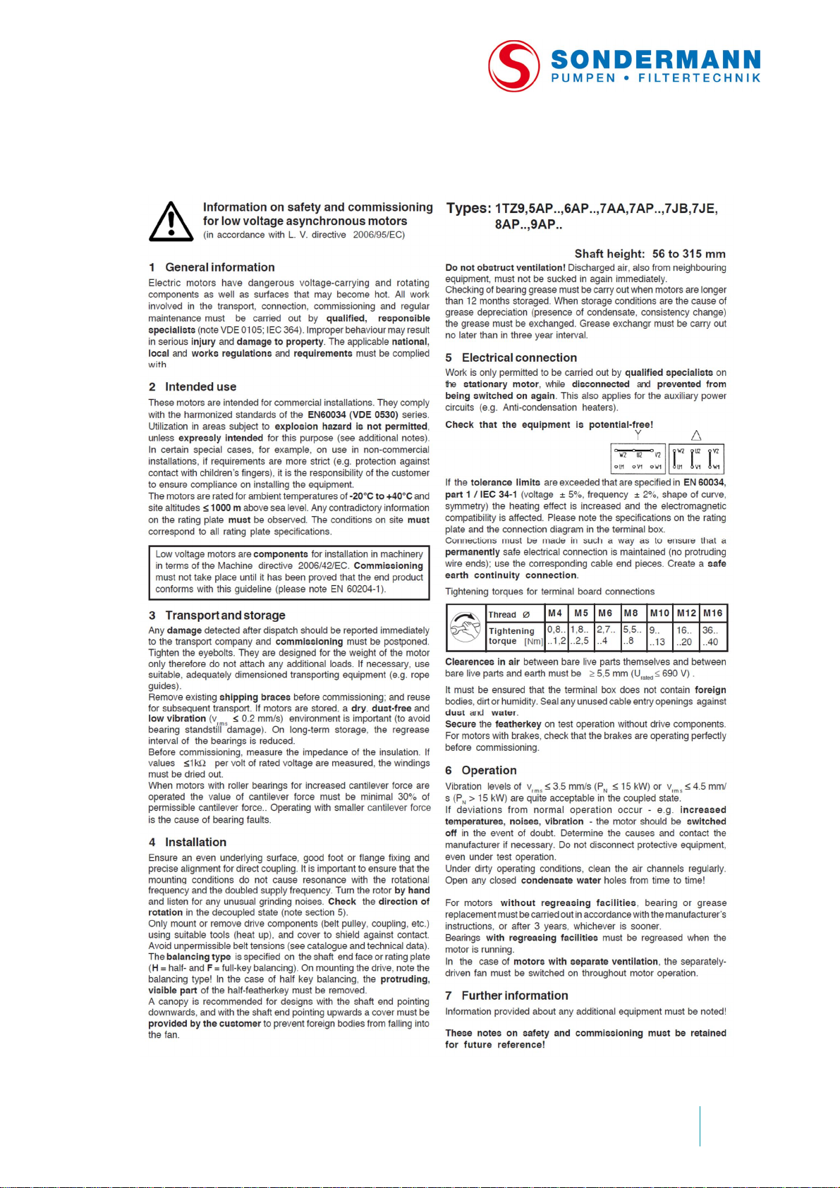
F) Safety infor mations electric motor
43
Page 44

G)Declaration of decontamination
According to various legal regula tion s on labor protection, incl uding the German
Workplace Reg ulations (ArbSt ättV), Hazard ous Subst ances Reg ulations (GefSt offV) and
regulations fo r the prevention of accid ents, as we ll as environme ntal regulations such as
the German Waste Act (AbfG) and the Water Resources Law (WHG), all industrial and
commercial enterprises are obliged to protect their employees and other persons as well
as the environment from harmful i nfluences and effects when handling hazard ous
substanc es.
We therefore ask you to attach a declaration of decontamination to any pump or
component you send us for repair, stating that you carefully cleaned and, if necessary,
thorough ly rinsed wit h neutral fluid the pump or component before you shipped it t o us.
Notwithstanding the receipt of this declaration, we reserve the right to reject its repair for
other reasons.
No SONDERMANN product or component of them will be accepted for service
or repair unless the declaration of decontaminatio n is enclosed!
Apart from that, we do NOT accept any pump that has been operated with radioactive
substances.
When sending in the pump or a component, please inform us if, despite ca refully
emptying and cleaning the pump, there are still some safety precautions required.
44
Page 45

Centrifugal
pump
MAGSON
Issue
1| 201
9-01Appendix
Declaration of Decontamination
The undersigned herewith declare that the follow ing pump and its accessories are h armless and
ask you to service and/or repair it for them.
Type:
......................................................................................... ..........................
......................................................................................... ..........................
Serial num b er :
............. ... .... .... ... .... .... .... ... .... .... .... ... .... .... .... ... .... .... ..... .... .... ... .... .... ... .... ....
Date of delivery:
............. .............. ........................... ............... ................ .......................... ....
Kind of problem:
...................................................................................................................
...................................................................................................................
Declaration:
The pump was not used to deliver harmful or noxious substances
□ but with the following fluids:
...................................................................................................................
...................................................................................................................
□ Before being shipped, the pump was carefully emptied and cleaned inside and outside.
□ There are no special safety precautions required.
□ It is necessary to take the following safety precautions with regard to residual fluids and waste
disposal:
...................................................................................................................
...................................................................................................................
Date: Signature:
45
Page 46

46
Page 47

Centrifugal pump
MAGSON
Issue
1| 201
9-01Index
47
Page 48

SONDERMANN
Pumpen + Filter GmbH & Co. KG
August-Horch-Straße 2
51149 Köln (Porz)
Phone: +49(0)2203 93940
Fax: +49(0)2203 939 448
[email protected]
www.sondermann-pumpen.de
© 2017 SON DERMANN Pumpen + Filter GmbH & Co. KG
Version 03 of Jan 2019; English version of the German original Operating Manual – Subject to technical
modifications
BA-MAS4-6; E
This operating manual is protected by copyright and must not be copied no r transmitted or used in any
form or by any means in full or in parts, unless explicitly authorized in writ ing by SONDERMANN Pumpen +
Filter GmbH & Co. KG.
 Loading...