

Page 1
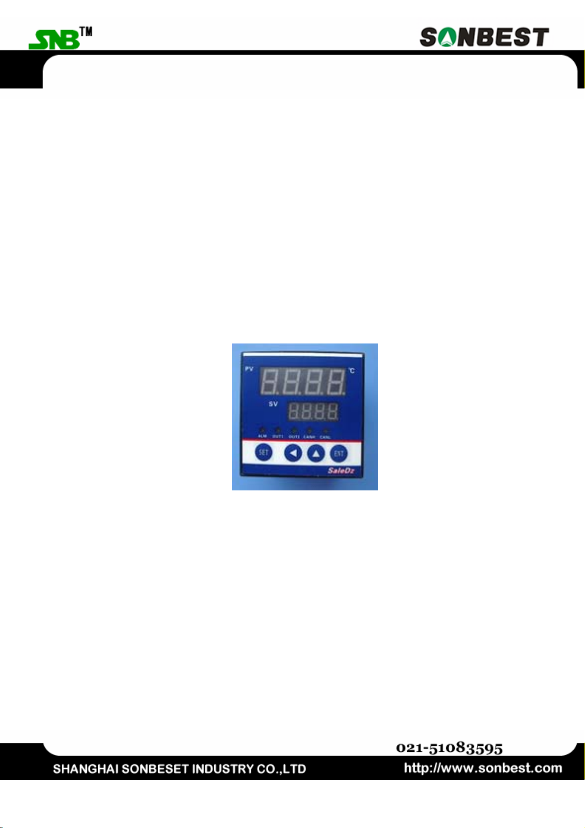
SLI1 Single bus intelligent temperature data logging devices Operating Manual
+086 021 51083595
SLI1
Single bus intelligent temperature data
logging devices Operating Manual
ShangHai Sonbest Industry Co,.Ltd Website:http://www.sonbest.com Page 1 Total 9
Page 2

SLI1 Single bus intelligent temperature data logging devices Operating Manual
+086 021 51083595
CONTENTS
I. Introduction............................................... 3
Second, the technical parameters ............................ 3
Third, the typical program ................................... 4
Fourth, the interface shows .................................. 5
POWER ........................................................................................................................................5
SENSOR TEST INTERFACE............................................................................................................. 6
Fifth. Instructions ........................................... 7
1. READ INTO THE NEW SENSOR (SET PASSWORD IS 1234) ........................................................... 7
2. TO SET THE ALARM LIMIT VALUE (SET PASSWORD IS 1244) ..................................................... 8
3. SETS THE CHANNEL IS DISPLAYED (SET PASSWORD IS 1254).................................................... 8
Sixth. Selection Guide ....................................... 8
Seventh, random list ........................................ 9
ShangHai Sonbest Industry Co,.Ltd Website:http://www.sonbest.com Page 2 Total 9
Page 3

SLI1 Single bus intelligent temperature data logging devices Operating Manual
+086 021 51083595
I. Introduction
SLI1 series of data logging devices model name have been renamed SLIT3 series.
SLI1 series of single-bus intelligent temperature data logging devices, with the U.S. DALLAS
line field bus technology, low temperature conditions to achieve the practical online instrument
monitoring program can be widely used in real-time temperature monitoring of a variety of data
acquisition applications.
SLI1 series of single-bus temperature detection apparatus can be intelligent digital
temperature sensor DS1820 series of products for temperature data collection, display, alarm
settings, data transmission, so that the temperature detection system for high circuit reliability,
low cost and simple wiring structure. Traditional temperature measurement system as an ideal
alternative, and its small size, measuring point and more flexible networking features. With
wireless or GPRS and field a single bus transfer (1-wire) technology, the DS1820 will spread
throughout the node via a wired or wireless means to link up with the monitoring center, to
reduce energy consumption, promote safe production purposes.
The instrument can be applied: (1) SMT industrial temperature data monitoring (2)
Electronic Equipment Factory of the temperature data monitoring (3) cold storage temperature
monitoring (4) storage temperature monitoring (5) pharmaceutical GMP monitoring system (6)
Environmental temperature monitoring (7) telecommunications room monitoring (8) Power
Plant / Power Plant (9) Power Plant / Power Plant (10) Temperature Monitoring (11) beer
production process temperature detection.
For ease of engineering network use, the instrument provides a secondary communication
protocol developed to support the secondary development. Users simply according to our
protocol can use any serial communication software to query and set equipment data.
Second, the technical parameters
Support sensor SLST1,DS18B20
Display temperature range
Display resolution
Temperature measurement
accuracy
Temperature rate 850ms / point
Channels Can be accessed by 1-24 points (see instrument
Alarm settings Set the alarm limit line
Baud Rate 19200 (other baud rate can be customized)
Communication port RS232 (optional CAN, RS485)
Power supply DC 5V 2A
Power Consumption 2W
ShangHai Sonbest Industry Co,.Ltd Website:http://www.sonbest.com Page 3 Total 9
-55℃~+125℃
0.1℃
0.5℃
identification, limit of single-bus sensors)
Page 4
SLI1 Single bus intelligent temperature data logging devices Operating Manual
Weight 270 grams
Storage temperature
Operating environment:
Support the bus cable length ≤200M
Hole Size 67×67mm
Dimensions:
-40 - 85℃
-40 - 85℃-40℃~+85℃
72×72×75mm³
+086 021 51083595
Third, the typical program
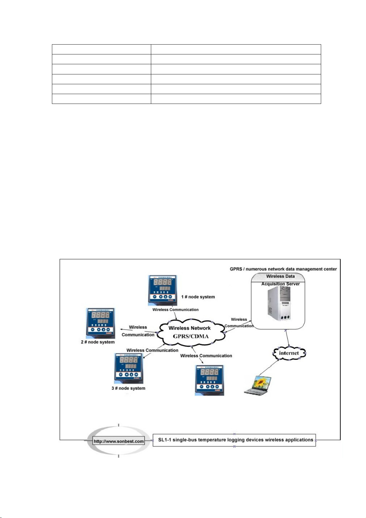
The most simple applications
SLI1 instruments directly through the RS232 interface with a computer or laptop
connection (optional RS232-USB converter) will be the scene data directly to a
computer for display, analysis and storage.
Program shown above, SLI1 will live through a single bus interface bus. DS1B20
chip temperature sensor can also be matching my company SLST series stainless
steel of various protective packaging of digital temperature sensor. Instrument
which can be accessed on the bus 6 sensors (to be expanded, customizable,
extendable to a maximum of 250 points). And each temperature sensor is received
by way of parallel bus. See wiring instructions.
Wireless applications
Wireless applications is an extension of the simplest applications. Wiring the scene,
with the most simple applications the same. Instrument through RS232 interface
ShangHai Sonbest Industry Co,.Ltd Website:http://www.sonbest.com Page 4 Total 9
Page 5

SLI1 Single bus intelligent temperature data logging devices Operating Manual
+086 021 51083595
with GRPS / CDMA or other wireless device, you can set up the wireless network.
Field data will be sent to the server or data collection centers, to achieve real-time
online monitoring of field data.
Fourth, the interface shows
Right picture shows the wiring behind the instrument panel, the panel on the pins
defined as shown on the right:
Pin
Number
1 +5V Power supply is positive, use the 5V power supply
2 GND Then the power negative
3 CANH No function of the instrument temporarily
4 CANL No function of the instrument temporarily
5 Normally
6 Public Relay output common pin
7 NC Relay output normally closed
8 VCC Positive power supply bus, the normal output value of 5V, not be
9 DQ1 Access to bus signals
10 DQ2 New sensor reading pin serial number identification
11 GND Negative power supply bus
12 RX RS232 standard serial port 2 pin connection
13 TX 3 pin RS232 standard serial port connection
14 GND 5 pin standard serial port RS232 connection
Definition Help
Relay output normally open
open
less than 3.7V
Power
The instrument input is DC 5V, supplied power for the 5V 2A. Use, please check the
voltage and polarity and then access equipment. 1 is a positive power supply input
voltage range :4.8-5 .5 V
RS232 Interface
RS232 interface is a standard serial interface, the pin is defined as follows:
2 foot-RX 3 Foot-TX 5 foot-GND, the serial interface can be connected directly to
your computer, but also with other instruments with the serial communication
settings for connection, use of non-cross-RS232 data cable.
Instruments on the back of pin
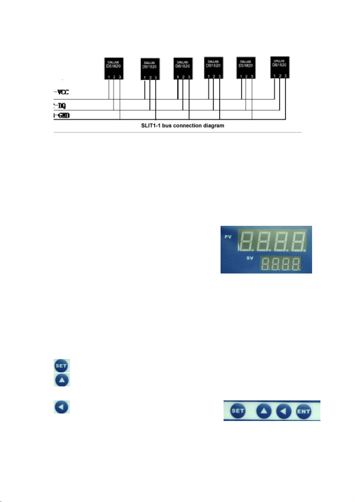
Bus Interface
Three wire bus interface, this interface can be accessed by a maximum of 200
meters the bus, the instrument can be connected up to standard six single-bus
temperature sensor wiring as follows:
ShangHai Sonbest Industry Co,.Ltd Website:http://www.sonbest.com Page 5 Total 9
Page 6
SLI1 Single bus intelligent temperature data logging devices Operating Manual
+086 021 51083595
Bus interface has three pins, the pin is defined as follows:
8 feet - the power is (VCC), this pin is the voltage output pin voltage is 5V
9 feet - the signal line (DQ), single bus signal line
11 feet - the power of negative (GND)
Sensor test interface
<Sensor test interface> is mainly used for reading the sensor into the new access
ID, the new sensor in the bus access, please access <sensor test interface> read
the serial number. And then access the bus. The new sensor read mode of
operation, see instructions.
Test interface is:
8 feet - the power is (VCC), this pin is the voltage
output pin voltage is 5V
10 feet - the signal line (DQ), the new sensor signal
access to the foot
11 feet - the power of negative (GND)
Display Panel
Instrument uses two rows of four LED display, as shown, the upper display
temperature data, the lower channel number display sensor. To cycle through
display, the user can close or open the corresponding button to set the channel.
Keyboard
Instrument set the four keys are:
–
"Settings button>, press the button to enter the settings into the state.
-
<Up button> This button is mainly used to switch the channel number, or
set the alarm temperature increase by 10 increments the alarm temperature.
-
<To the left> this key principal in the set
alarm temperature increase by 1 increment
value or set the alarm temperature channel is
shown.
-
ShangHai Sonbest Industry Co,.Ltd Website:http://www.sonbest.com Page 6 Total 9
Page 7
SLI1 Single bus intelligent temperature data logging devices Operating Manual
+086 021 51083595
- <ENT> Canceled after confirmation settings,
enter the normal display state.
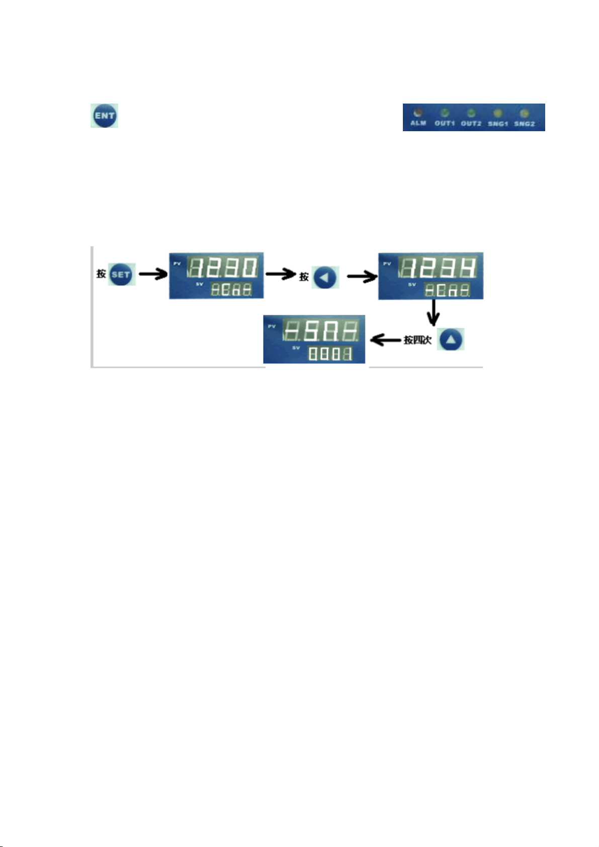
Equipment to set up five indicators, which ALM is warning light, OUT1, OUT2 for
the alarm output indicator, the instrument is no such standard function. When
working properly, OUT1 to Always, and OUT2 off. SNG1, SNG2 for
communications status indicator, when the serial port with data exchange, SNG2
be indicator flashes. But only for RS485 or CAN SNG2 equipment, used to indicate
the appropriate communication status.
Fifth. Instructions
To prevent misuse, the system set a password access. As shown above, is to enter the setting
state of the whole process, while the upper value of the digital value to the password value is
displayed, the instrument will automatically set to the appropriate state.
1. Read into the new sensor (set password is 1234)
The instrument before use, ensure that access to the serial number of the sensors on the bus
have been stored in the instrument. Otherwise, the system will not recognize. The new sensor
read the steps below:
1) define the correct access to the sensor then the sensor pin test interface. Please note that
the sensor test interface marked VCC, DQ, GND, this pin is set with a single sensor device
bus-one correspondence, can not take the wrong.
2) enter the set state and set (set password is 1344)
Pressed as following:
<SET> Key press, click <up button>, and then looked <LEFT>, when the last row of the digital
control, display value reaches 1344, that reads the serial number into the state, this time on the
row of display - SN-, the next row of display 0001, which is the lower channel number 000x.
Read the serial number into the state, which can be <up arrow> to switch channels. For
example, I hope that the new access to the sensor 2, channel display, just click <up button>, the
lower display shows "0002", the press <SET> key, this time to wait for a few seconds, when the
last row Show "-PS-", it said, has successfully test interface access to the channel 2 sensor
reading. When the remains of other new sensor reading, the need to replace <sensor test
interface> on the sensor, switch <up arrow> to select the channel number, press <SET>, until
ShangHai Sonbest Industry Co,.Ltd Website:http://www.sonbest.com Page 7 Total 9
Page 8

SLI1 Single bus intelligent temperature data logging devices Operating Manual
the upper display when the "-PS-" time. After reading the serial number, according to <ENT>
key to exit setting mode.
+086 021 51083595
2. To set the alarm limit value (set password is 1244)
The instrument can be alarm values for each sensor set, when any one sensor
temperature exceeds the upper limit set, the instrument that will alarm. Set as
follows:
The same with the above setup, when the row is "1244", the instrument that is
immediately set into the alarm state, this time on the display shows "0050", that is
not set off the channel, the system default limit alarm value of 50 degrees. Lower
display shows "0001" character, the last one that is channel number, through
<LEFT> to set the alarm value (the value cycle, when more than 125, it will
automatically become 0, so that you can set the low The following alarm 50), by <up
the value> to switch round after round. When all the alarm settings are finished,
click <ENT> to identify and enter into the normal display state.
3. Sets the channel is displayed (set password is 1254)
Although the instruments to support six sensors, but the actual use of only 2 or less then 6 months, we
can not access this feature off the sensor channel.
We at <SET>, through <the left "(press 2 the next)," up arrow "(by 4 down) switch, when the display
shows" 1254 ", the channel is set to enter the state, this time on the row Show "-ON-" or "-OFF",
available at this time <up arrow> to switch channels, use <to the right> to set on or off. When set up,
according to <ENT> to identify and enter into the normal display state.
Sixth. Selection Guide
No. Channels Model
1
2
3
4
5
1 点
6 点
12 点
20 点
24 点
SLI1-1/1 Single instrument, without identifying the sensor
SLI1-1/6 6 meters, bus, run-time automatic identification
SLI1-1/12 12 meters, bus, run-time automatic identification
SLI1-1/20 20 points meter, bus, run-time automatic
SLI1-1/24 24-point instrument, bus, run-time automatic
Remarks
serial number
identification
identification
Other non-standard number of channels can be customized according to user
requirements
ShangHai Sonbest Industry Co,.Ltd Website:http://www.sonbest.com Page 8 Total 9
Page 9

SLI1 Single bus intelligent temperature data logging devices Operating Manual
Seventh, random list
No.
Intelligent temperature data
1
2
3
4
ShangHai Sonbest Industry Co,.Ltd
circuit tester
Monolithic Power
Serial Line 1
Manual (certificate) 1
Tel:+86 021 51083595
Website:http://www.sonbest.com
ShangHai , China
Name Type Quantity Remarks
SLI1-1 1
DC5V 2A 1
+086 021 51083595
ShangHai Sonbest Industry Co,.Ltd Website:http://www.sonbest.com Page 9 Total 9
 Loading...