


1
Introduction
Thank you for purchasing Sonance Visual Performance Series
Extreme Speakers. These weatherproof 6" speakers can provide
superior sound quality for high-humidity areas and are built to
survive temperature extremes from –30°F – +175°F (–34°C –
+79°C). Their shallow depth makes them easy to install in a variety of challenging spaces. Visual Performance Extreme speakers
provide excellent sound in yachts, saunas, steam rooms, and hot
tub areas.
This manual covers the following speaker models: VP65 XT
(rectangular), VP65R XT (round), VP65S XT (square), VP65R SST
XT (round, Single-Stereo Technology
®
).
Box Contents
Sonance VP65 XT, VP65R XT, and VP65S XT speaker boxes contain
(2) speakers, (2) paint plugs (installed on the fronts of the
speakers), (2) paintable grilles and (1) mounting cutout
template.
Sonance VP65R SST XT speaker boxes contain (1) speaker,
(1) plastic paint plug (installed on the front of the speaker),
(1) paintable grille and (1) mounting cutout template.
Speaker Placement
Stereo Speaker Placement (VP65 XT)
• Place the left and right speakers on the same wall, from 6 to
10 feet (1.8 – 3m) apart.
• If the listeners will be seated the speakers should be located
38 – 42 (97 – 107cm) inches from the floor.
• If listeners will be standing the speakers should be located
5 feet (1.5m) from the floor.
• The ideal listening distance will be between 4 and 10 feet (1.2
and 3m) away from the speakers. The best stereo performance
will be midway between the speakers.
Use Figure 1 (next column) as a guide
Distributed Audio Placement
(VP65R XT/VP65S XT/VP65R SST XT)
Sonance VP65R XT, VP 65S XT and VP65R SST XT in-ceiling
speaker models provide excellent coverage in distributed
audio systems from a wide variety of installation locations.
The table and illustration in Figure 2 show how far apart
speakers can be placed at various ceiling heights while still
providing good coverage for all listeners.
The VP65R SST XT reproduces both stereo channels from a single
location, making it ideal for use in bathrooms, saunas, or in any
location where a pair of stereo speakers would be impractical.
Before Installation: Retrofit
1. Determine the location for the speaker (see Speaker
Placement on page 1).
2. Perform an obstruction survey to be certain that there are
no studs, conduit, pipes, heating ducts, pocket doors or
air returns in the wall cavity that will interfere with the
speaker.
INSTRUCTION MANUAL
VISUAL PERFORMANCE® SERIES
EXTREME SPEAKERS
S
AFETYWARNING
:
THESE SPEAKERS HAVE FASTMOUNT
®
TABS THAT PREVENT THE
SPEAKER FROM FALLING OUT OF THE MOUNTING HOLE DURING THE
INSTALLATION PROCESS
.
T
HE EDGES OF THEFASTMOUNT TABS ARE VERY SHARP
.
U
SE CAUTION WHEN HANDLING THE SPEAKER
.
SPEAKER SPACING (IN FEET)
FOR A DISTRIBUTED AUDIO SYSTEM
STANDING LISTENER
SEATED LISTENER
10-
FOOT CEILING
12-
FOOT CEILING
14-
FOOT CEILING
8-
FOOT CEILING 9.5’ (2.9m) Apart
13.5’ (4.1m) Apart
17.5’ (5.3m) Apart
21.5’ (6.6m) Apart
5.7’ (1.7m) Apart
9.7’ (3.0m) Apart
13.7’ (4.2m) Apart
17.7’ (5.4m) Apart
FIGURE 2: DISTRIBUTED AUDIO SPEAKER SPACING
FIGURE 1: STEREO SPEAKER PLACEMENT
6‘ – 10’ (1.8m – 3m)
5‘ (1.5m)
(Standing Listeners)
38” – 42”
(97cm – 107cm)
(Seated Listeners)
Apart
SPEAKER
PACING
S
COVERAGE
REA
A
C
OVERAGE
REA
A
2
SONANCE VISUAL PERFORMANCE®EXTREME SPEAKERS
3. VP Extreme speakers require the following mounting cutouts:
• VP65 XT: 6
15
/
16” (176mm) wide by 10¾” (273mm) high, with
at least 2½” (64mm) of depth within the mounting cavity.
• VP65R XT: 8¼” (210mm) diameter, with at least 3½”
(89mm) of depth within the mounting cavity.
• VP65S XT: 8¼” (210mm) wide by 8¼” (210mm) high, with at
least 3½” (89mm) of depth within the mounting cavity.
• VP65R SST XT: 8¼” (210mm) diameter, with at least 3½”
(89mm) of depth within the mounting cavity.
4. Position the included mounting cutout template where the
speaker is to be located and pencil an outline on the wall
or ceiling.
• If you are unsure about obstructions, drill a small hole in
the center of the outline and insert a coat hanger wire into
the hole to feel-around for possible obstructions.
5. Cut the mounting hole using tools appropriate for the
construction, and run the speaker wires from the mounting
hole to the amplifier location.
• Consult local building codes before running speaker wires
through walls.
Installation
Sonance VIsual Performance Series Extreme speakers feature
exclusive FastMount
®
tabs and an integral RotoLock®mounting
system for quick mounting directly into existing walls and ceilings.
WARNING: THE EDGES OF THE FASTMOUNT TABS
ARE VERY SHARP. USE CAUTION WHEN HANDLING THE SPEAKER.
1. Remove the paint plug from the speaker.
2. Strip ¼” – ½” (6mm – 13mm) of insulation from each
speaker lead. Twist the strands or tin the exposed wire
with solder to ensure that there are no stray strands.
(Stray strands that touch each other can cause a shortcircuit that can damage the amplifier.)
3. The speaker’s connector posts are spring-loaded. Push the top
of each connector post down to open the connector and insert
the exposed wires into the holes in the posts (see Figure 3).
• The speaker’s positive post is labeled with a red dot; the
negative post is labeled with a black dot.
• The VP65R SST XT has two sets of connection terminals,
located on opposite sides of the crossover board.
• After making all connections, double-check that you
connected amplifier “+” to speaker “+” and amplifier “–”
to speaker “–”.
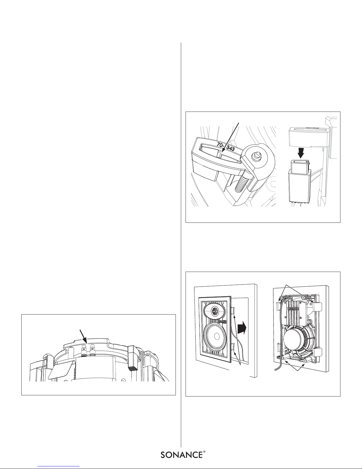
4. As shipped, the RotoLock clamps can accommodate a maximum wall or ceiling material thickness of 1¼” (32mm).
NOTE: IFYOU’RE INSTALLING THE VP65R XT, VP65S XT, OR
VP65R SST XT INTO CEILING MATERIAL THAT IS THICKER THAN
1¼” (32MM), YOU CAN REMOVE THE ‘FEET’ OF THE ROTOLOCK
CLAMPS
, WHICH WILL ALLOW YOU TO CLAMP THE SPEAKER TO CEIL-
ING MATERIAL THAT IS UP TO 1¾” (44MM) THICK. TO REMOVE THE
CLAMP FEET
, USE A SMALL SCREWDRIVER TO GENTLY RELEASE THE
LOCKING LEVERS
(F IGURE 4, LEFT). THEN REMOVE THE FEET FROM
THE CLAMPS
(F IGURE 4, RIGHT).
5. Make sure all the RotoLock clamps are retracted so that they
are tucked within the mounting hole’s border. Insert the
speaker into the mounting hole (Figure 5, left). The
FastMount tabs will prevent the speaker from falling out of
the mounting hole, allowing you to let go of the speaker to
pick-up tools or other items (Figure 5, right).
NOTE: THE FASTMOUNT TABS ARE DESIGNED FOR ONE-TIME USE
ONLY
. IF THE SPEAKER IS REMOVED FROM THE MOUNTING HOLE THE
FASTMOUNT TABS WILL DISCONNECT AND REMAIN INSIDE THE WALL
OR CEILING
.
6. Tighten the four screws on the front of the speaker baffle. The
RotoLock clamps will automatically rotate into position and
begin clamping the speaker (Figure 6, page 3).
FIGURE 5: INSERTING THE SPEAKER INTO THE MOUNTING HOLE
FIGURE 3 CONNECTION TERMINALS
Connection Terminals
(1 Set on VP65R XT, VP65S XT, VP65 XT;
2 Sets on VP65R SST XT)
Locking Lever
Remove Foot
FIGURE 4: REMOVING THE ROTOLOCK CLAMP FEET
FastMount
Tabs
FastMount
Tabs
RotoLock Clamps
(retracted)
 Loading...