

Introduction
Thank you for purchasing Sonance Visual Performance
®
Series Medium rectangle speakers. When properly installed your
new speakers will give you years of entertainment pleasure.
Box Contents
Each Sonance Visual Performance Series Medium rectangle
speaker box contains (2) Visual Performance Series speakers,
(2) paint plugs (installed on the fronts of the speakers),
(2) paintable grilles and (1) mounting cut-out template.
Speaker Placement
Home Theater Speaker Placement
Left, Center & Right Speakers
• Place the left & right speakers on either side of the video
screen, 6 – 10 feet (1.8m – 3m) apart and 3 – 4 feet
(0.9m – 1.2m) from the floor.
• If possible, locate the center speaker at the same height as the
left & right channel speakers.
• If you must place the center speaker above or below a video
screen, place it no more than 2 feet (0.6m) above or below the
center of the left and right speakers. This will maintain consistent tonality between all three front channel speakers.
• The main listening position should be 8 – 12 feet
(2.4m – 3.7m) away from the speakers.
Use
Figure 1
as a guide.
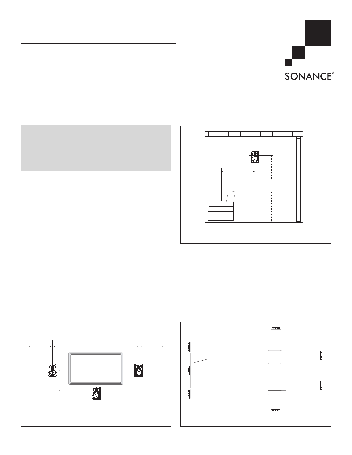
Surround Speakers (5.1-Channel System)
Locate the surround channel speakers on the side walls 2 – 6 feet
(0.6m – 1.8m) behind the listening position, 5 – 7 feet
(1.5m – 2.1m) from the floor. Use
Figure 2
as a guide.
Surround Speakers (7.1-Channel System)
• LEFT & RIGHT SURROUND SPEAKERS: Place the left and right
surround speakers directly to the sides of the listening position,
at least 5 feet from the floor.
• S
URROUND BACK SPEAKERS: Place the surround back speakers in
the rear wall, 3 – 6 feet (0.9m – 1.8m) apart and 5 – 7 feet
(1.5m – 2.1m) from the floor.
Use
Figure 3
as a guide.
INSTRUCTION MANUAL
VISUAL PERFORMANCE® SERIES
MEDIUM RECTANGLE SPEAKERS
S
AFETYWARNING
:
THESE SPEAKERS HAVE FASTMOUNT
®
TABS THAT PREVENT THE
SPEAKER FROM FALLING OUT OF THE MOUNTING HOLE DURING THE
INSTALLATION PROCESS
.
T
HE EDGES OF THEFASTMOUNT TABS ARE VERY SHARP
.
U
SE CAUTION WHEN HANDLING THE SPEAKER
.
18"
(0.5m)
From Side
Wall
18"
(0.5m)
From Side
Wall
2'
(0.6m)
max.
6' – 10'
(1.8m – 3m)
Apart
FIGURE 1: LEFT, CENTER & RIGHT CHANNEL
HOME THEATER SPEAKER PLACEMENT
5' – 7'
(1.5m – 2.1m)
2' – 6'
(0.6m – 1.8m)
FIGURE 2: 5.1-CHANNEL HOME THEATER SURROUND SPEAKER
PLACEMENT
Right Surround
Speaker
Left Surround
Speaker
Left
Front
Speaker
Right
Front
Speaker
Video
Screen
Center
Speaker
Left
Surround Back
Speaker
Right
Surround Back
Speaker
FIGURE 3: 7.1-CHANNEL HOME THEATER SPEAKER PLACEMENT

2
SONANCE VISUAL PERFORMANCE®MEDIUM RECTANGLE
Stereo (2-Channel) Placement
• Place the left and right speakers 6 – 10 feet (1.8m – 3m) apart,
with the main listening position as close to midway between
the speakers as possible.
• The speakers should be at least 2 feet (0.6m) away from the
side walls.
• The main listening position should be 4 – 10 feet (1.2m – 3m)
away from the speakers.
• In most cases pivoting the tweeter of each speaker directly
towards the main listening position will help maximize the
stereo soundstage.
Use the left and right speaker placement in
Figure 1
, on page 1,
as a guide.
Before Installation: Retrofit
1. Determine the location for the speaker (see
Speaker Placement
on page 1).
2. Perform an obstruction survey to be certain that there are no
studs, conduit, pipes, heating ducts, pocket doors or air returns
in the wall cavity that will interfere with the speaker.
3. Mounting space requirements: 6
15
⁄16” (176mm) wide by
10¾” (273mm) high cut-out and at least 3½” (89mm) mounting depth. Medium ThinLine rectangle speakers require at
least 2½” (64mm) mounting depth.
4. Position the included cut-out template where the speaker is to
be located and pencil an outline on the wall. If you are unsure
about obstructions, drill a small hole in the center of the
outline and insert a coat hanger wire into the hole to feelaround for possible obstructions.
5. Cut the mounting hole using a keyhole or drywall saw, and
run the speaker wires from the mounting hole to the amplifier
location.
NOT E: CONSULT LOCAL BUILDING CODES BEFORE RUNNING
SPEAKER WIRES THROUGH WALLS.
Before Installation: IR Plug
Sonance Visual Performance Series
Medium rectangle speakers have a
plug for installing an IR receiver into
the speaker’s front baffle (see
Figure
4
). In systems where the electronics
are placed in an inconvenient location this allows remote controls to be
aimed at the front of the room instead
of at the electronics.
The IR plug is in the form of a bolt
and retaining nut. To remove the
plug, unscrew the nut (located behind
the baffle, see
Figure 5
) and remove
the bolt. The hole is designed to
receive a Sonance OptiLinQ
®
SMR1
or SMR1P Surface-Mount IR receiver.
Insert the IR receiver through the
front of the speaker baffle and use
the nut included with the receiver to
secure it to the baffle.
Installation
Sonance Visual Performance Series speakers feature exclusive
FastMount tabs and an integral Roto-Lock
®
mounting system for
quick mounting directly into existing walls.
WARNING: THE EDGES OF THE FASTMOUNT TABS
ARE VERY SHARP. USE CAUTION WHEN HANDLING
THE SPEAKER.
1. Remove the paint plug from the speaker.
2. Strip ¼” – ½” (6mm – 12mm) of insulation from each speaker lead. Twist the strands or tin the exposed wire with solder
to ensure that there are no stray strands. (Stray strands that
touch each other can cause a short-circuit that can damage
the amplifier.)
3. The speaker’s connector posts are spring-loaded. Push the top
of each connector post down to open the connector and insert
the exposed wires into the holes in the posts.
The speaker’s positive
post is labeled with a
red dot; the negative
post is labeled with a
black dot. Double-check
that you connected
amplifier “+” to speaker
“+” and amplifier “–” to
speaker “–”.
4. Make sure all the RotoLock clamps are retracted so that they are
tucked within the mounting hole’s border. Insert
the speaker into the hole
in the wall (
Figure 6
).
The Roto-Lock system
can accommodate a
maximum wall material
thickness of 1¼”
(32mm).
The FastMount tabs will
prevent the speaker from
falling out of the mounting hole, allowing you to
let go of the speaker to
pick-up tools or other
items (
Figure 7
).
NOTE : THE FASTMOUNT TA BS
ARE DESIGNED FOR ONE-
TIME USE ONLY. IFTHE
SPEAKER IS REMOVED FROM
THE MOUNTING HOLE THE
FASTMOUNT TABS WILL
DISCONNECT AND REMAIN
INSIDE THE WALL.
Roto-Lock Clamp
(retracted)
Roto-Lock Clamp
(retracted)
FIGURE 6: INSERTING THE SPEAKER
INTO THE MOUNTING HOLE
FastMount
Tabs
Roto-Lock Clamps
(retracted)
FIGURE 7: FASTMOUNT TABS AND
ROTO-LOCK CLAMPS
FIGURE 4: IR PLUG
FIGURE 5: IR PLUG
RETAINING NUT
IR Plug
Retaining Nut
 Loading...