


Introduction
Thank you for purchasing a Sonance Visual Performance
®
Series Woofer. When properly installed your new woofer will
improve the bass performance of your entertainment system.
Box Contents
Each Sonance Visual Performance Series Woofer box contains
(1) Visual Performance Series Woofer, (1) paint plug (installed
on the front of the woofer), (1) paintable grille and (1) mounting
cutout template.
Before You Begin
All Visual Performance Series Woofers are intended to be used
with the Sonamp
®
A800 Subwoofer Amplifier (available separately).
The A800 features adjustments that allow for proper setting of the
crossover frequency between the woofer and the system’s other
speakers, and for setting the woofer’s phase and volume.
Woofer Placement
In-Wall
For the highest output and best overall performance, in-wall
woofers should be placed on the same wall as the system’s left
and right speakers, in one of the corners.
IMPORTANT: The Woofer should NOT be
mounted in the same stud bay as any of the
system’s other speakers.
Use
Figure 1
as a guide.
In-Ceiling
For the highest output and best overall performance, in-ceiling
woofers should be placed in one of the ceiling’s corners.
IMPORTANT: The Woofer should NOT be
mounted in the same ceiling bay as any of the
system’s other speakers.
Use
Figure 2
as a guide.
Before Installing the Woofer
1. Determine the location for the woofer (see
Woofer Placement
).
2. Perform an obstruction survey to be certain that there are no
studs, conduit, pipes, heating ducts, pocket doors or air
returns in the cavity that will interfere with the woofer.
3.
Mounting space requirements:
• Rectangle woofers: 8½" x 14½” (216mm x 368mm)
cut-out; 3
7
/
8” (98mm) mounting depth.
• Round woofers: 10
1
/
8” (257mm) diameter cut-out;
5
7
/
8” (149mm) mounting depth.
• Square woofers: 10¼” x 10¼” (260mm x 260mm)
cut-out; 5
7
/
8” (149mm) mounting depth.
4. Position the included cut-out template where the woofer is to
be located and pencil an outline on the wall or ceiling.
• If you are unsure about obstructions, drill a small hole in
the center of the outline and insert a coat hanger wire into
the hole to feel-around for possible obstructions.
5. Cut the mounting hole using a keyhole or drywall saw, and
run the speaker wires from the mounting hole to the amplifier
location.
NOT E: CONSULT LOCAL BUILDING CODES BEFORE RUNNING
SPEAKER WIRES THROUGH WALLS OR CEILINGS.
INSTALLATION MANUAL
VISUAL PERFORMANCE® SERIES
IN-WALL & IN-CEILING WOOFERS
S
AFETYWARNING
:
THESE WOOFERS HAVE FASTMOUNT
®
TABS THAT PREVENT THE
WOOFER FROM FALLING OUT OF THE MOUNTING HOLE DURING THE
INSTALLATION PROCESS
.
T
HE EDGES OF THEFASTMOUNT TABS ARE VERY SHARP
.
U
SE CAUTION WHEN HANDLING THE WOOFER
.
In-Wall
Woofer
In-Wall
Speakers
FIGURE 1: IN-WALL WOOFER PLACEMENT
In-Ceiling Woofer
In-Ceiling
Speakers
FIGURE 2: I N-CEILING WOOFER PLACEMENT
2
SONANCE VISUAL PERFORMANCE®WOOFERS
Installing the Woofer
Sonance Visual Performance Series Woofers feature exclusive
FastMount tabs and an integral Roto-Lock
®
mounting system for
quick mounting directly into existing ceilings.
WARNING: THE EDGES OF THE FASTMOUNT TABS
ARE VERY SHARP. USE CAUTION WHEN HANDLING
THE WOOFER.
1. Remove the paint plug from the woofer.
2. Strip ¼” – ½” (6mm – 12mm) of insulation from each lead
of the speaker wire. Twist the strands or tin the exposed wire
with solder to ensure that there are no stray strands. (Stray
strands that touch each other can cause a short-circuit that
can damage the amplifier.)
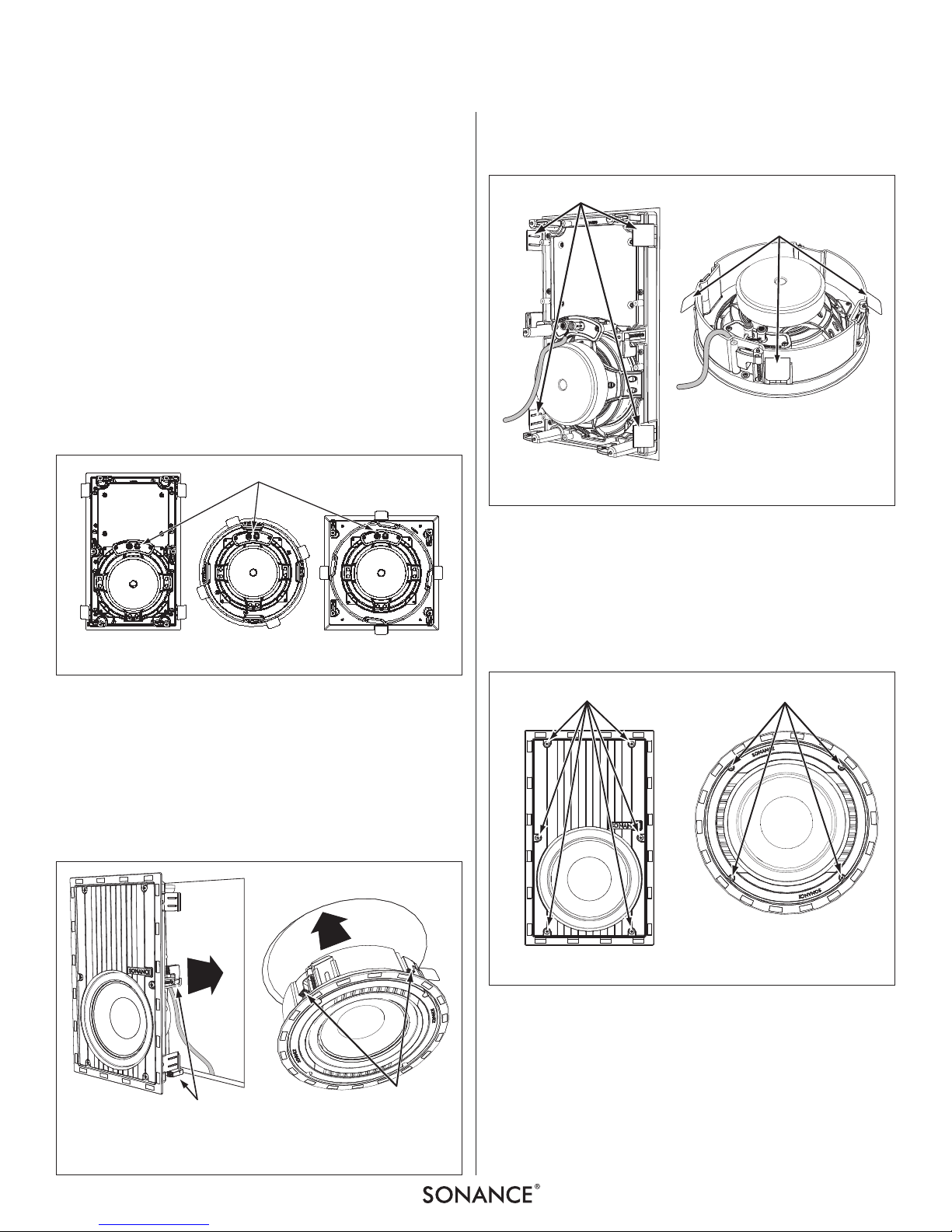
3. The woofer’s connector posts are spring-loaded. Push the top
of each connector post down to open the connector and
insert the exposed wires into the holes in the posts
(see
Figure 3
)
The woofer’s positive post is labeled with a red dot;
the negative post is labeled with a black dot. Double-check
that you connected amplifier “+” to woofer “+” and
amplifier “–” to woofer “–”.
4. Make sure all the Roto-Lock clamps are retracted so that they
are tucked within the mounting hole’s border. Insert the
woofer into the hole in the wall or ceiling (
Figure 4
).
The Roto-Lock system can accommodate a maximum wall or
ceiling material thickness of 1¼” (32mm).
The FastMount tabs will prevent the woofer from falling out
of the mounting hole, allowing the installer to let go of the
woofer to pick-up tools or other items (
Figure 5
).
NOTE : THE FASTMOUNT TA BS A RE DESIGNED FOR ONE-TIME USE
ONLY. IF THE WOOFER IS REMOVED FROM THE MOUNTING HOLE
THE FASTMOUNT TABS WILL DISCONNECT AND REMAIN INSIDE
THE WALL OR CEILING.
5. Tighten the screws on the front of the woofer baffle. The RotoLock clamps will automatically rotate into position and begin
clamping the woofer (
Figure 6
).
When you notice resistance on the screws the woofer has
been clamped successfully.
IMPORTANT: ALWAYS USE LOW-TORQUE SETTINGS; NEVER
OVER-TIGHTEN.
NOT E: ADJUSTING THE TENSION OF THE ROTO-LOCK CLAMPS
SO THAT THE WOOFER FRAME IS FLAT WILL HELP ENSURE THAT THE
GRILLE CONTACTS THE WALL OR CEILING ALL THE WAY AROUND
THE WOOFER FOR A PROPER FIT.
Connector Posts
FIGURE 3: VP WOOFER CONNECTOR POSTS
Roto-Lock Clamps
(retracted)
Roto-Lock
Clamps
(retracted)
FIGURE 4: INSERTING THE WOOFER IN THE MOUNTING HOLE
FastMount Tabs
FastMount Tabs
FIGURE 5: FASTMOUNT TABS
Roto-Lock Screws
Roto-Lock Screws
FIGURE 6: TIGHTENING THE ROTO-LOCK SCREWS
 Loading...