


INTRODUCTION
Thank you for purchasing a Sonance Symphony Single Stereo Technology®
(SS
TR
) speaker. When properly installed, this speaker will give you many
years of entertainment pleasure. To get the most out of your new speaker, please read this manual thoroughly before you begin installation.
To achieve the best performance, Sonance recommends that this
speaker be installed by a Sonance Authorized Dealer/Installer.
This manual covers both the Symphony S623SS
TR
and Symphony S621SS
TR
speaker models.
PARTS LIST
Your Sonance Symphony in-ceiling speakers include the following:
• (1) Sonance Symphony Speaker
• (1) Paintable Grille
• (1) Plastic paint plug to protect speakers during painting
• (1) Mounting cutout template (in packaging)
OPTIONAL ACCESSORIES
Symphony FlexBracket (part# 92092) and Symphony Staple Template (part#
901049) — Plastic templates to reserve a mounting hole for the speaker
in new construction. Designed to be used with the RotoLock® mounting system.
Symphony Coverplate (part# 92094) — Covers the hole made by the
FlexBracket during construction until the speaker is installed.
Symphony Retrofit Enclosure (part# 92098) — Molded enclosure that
reduces sound transmission into adjacent rooms and spaces. Can be
used in installations where the speaker is retrofitted into existing walls.
Sonafill®In-Ceiling System (part# 91928) — Retrofittable acoustical
treatment for in-ceiling speakers consisting of two pillows and four tiles
that virtually eliminates noises produced by resonating drywall.
Dramatically improves midbass sound quality and reduces sound
transmission into adjacent rooms.
Symphony Acoustic Enclosure (part# 91688) — ½” MDF enclosure that
provides ideal acoustic performance and maximum reduction of
sound transmission into adjacent spaces. Designed for use only in new
construction.
Fire-Rated Back Can (part# 91906) — Meets ASTM E 119, CAN/ULC S 101,
NFPA 251, UBC 7-1 and UL 263 criteria for commercial installations.
SPEAKER PLACEMENT
Sonance Symphony SSTRspeakers combine the outputs of your
receiver’s or amplifier’s left and right stereo channels, and play both
stereo channels from just one speaker.
Symphony SSTRspeakers are ideal for use in hallways, bathrooms,
closets, or in any location where listeners will be moving around and a
pair of stereo speakers would be impractical.
The location of the speaker should be determined by considering your
primary listening location as well as aesthetic values. Because a single
Symphony SS
TR
speaker reproduces both stereo channels, Symphony
SS
TR
speakers will deliver outstanding performance from a wide variety
of locations.
For optimum results contact your Authorized Sonance Dealer for
advice.
WIRE GAUGE
Extra resistance in the speaker wire can make a speaker sound less
dynamic and reduce definition of the bass frequencies. In extreme cases,
it can even attenuate high frequencies. Also, amplifier power is wasted in
wire with extra resistance, reducing your system’s maximum output level.
To prevent degrading sound quality, the total wire resistance should be
less than 10% of the speaker’s impedance.This means that for an 8-ohm
speaker, the total resistance of the wire should be less than 0.8 ohms.
Refer to the following table when selecting the proper wire gauge for
your system:
PREPARING THE INSTALLATION LOCATION
All Sonance speakers are designed to be relatively insensitive to
variations in enclosure volume. To achieve the ultimate performance
from your speaker, the wall or ceiling bay can be sectioned-off to
form a back box. Building such an enclosure will create a dramatic
improvement in bass performance and power handling.
Ideal back box volume requirements:
Symphony S623SS
TR
1.5 ft
3
Symphony S621SS
TR
1.0 ft
3
Insulating the Wall or Ceiling Cavity
To reduce sound transmission to adjacent rooms and further improve
speaker performance, insulate the wall or ceiling cavity by inserting a
sheet of unfaced fiberglass insulation above and below the speaker.
To reduce noise produced by unsupported drywall, install fiberglass
insulation in the wall or ceiling bays adjacent to the speaker location.
Symphony Retrofit Enclosures
For installations where it isn’t possible to section-off the wall or ceiling
bay to form a back box (such as when you’re retrofitting the speakers
into an existing ceiling), you can effectively reduce sound transmission
into adjacent rooms by fitting the speakers with optional Symphony
Retrofit Enclosures (part# 92098). This enclosure is designed specifically to be used with Symphony speakers, and will noticeably reduce sound
“spillover”from the rear of the speakers into adjacent rooms and spaces.
INSTALLING THE SPEAKERS
New Construction
For installations in new construction, Sonance recommends using
a Symphony FlexBracket (part#92902) to reserve a location for the
speaker. The FlexBracket is nailed or screwed to the studs and serves as
a guide for the drywaller so that the speaker hole will be in the desired
location once the drywall is installed.
1
INSTRUCTION MANUAL
SONANCE SYMPHONY®SERIES
SINGLE STEREO TECHNOLOGY
®
SPEAKER
Wire resistance in Ohms vs. length of cable run
Distance in Feet 50' 100' 150' 200' 250' 300'
20 gauge
18 gauge
16 gauge
14 gauge
12 gauge
10 gauge
1.04
.65
.41
.26
.16
.10
2.07
1.30
.82
.52
.32
.20
3.11
1.96
1.22
.77
.49
.31
4.14
2.61
1.63
1.03
.65
.41
5.18
3.26
2.04
1.29
.81
.51
6.22
3.91
2.45
1.55
.97
.61
2
Symphony FlexBrackets are compatible with the RotoLock mounting
system (see Retrofit, below).
Retrofit
Symphony Speakers feature an integral RotoLock® mounting system for
quick mounting directly into existing ceilings and walls. Once the hole is
cut and the cable is run, you can install the speaker in a matter of seconds.
1. Determine the location for the speaker (see Speaker Placement).
2. Perform an obstruction survey to be certain that there are no studs,
conduit, pipes, heating ducts or air returns that will interfere with the
speaker.
3. The cutout for Symphony SS
TR
Speakers is 85/32” (207mm). There
also must be at least 5
3
/16” (132mm) depth within the ceiling or wall
cavity for the speaker.
4. Find the cutout template provided in the speaker packaging. Position
the template where the speaker is to be located and pencil an outline
on the wall or ceiling.
• If you are unsure about obstructions, drill a small hole in the center
of the outline and insert a coat hanger wire into the hole to
feel-around for possible obstructions.
5. Cut the hole using a drywall saw, and run the speaker wires.
6. Remove the paint plug from the speaker.Connect the speaker wires to
the terminals on the back of the speaker.:
• Connect the left channel amplifier ‘+’ wire to the red ‘Left’ speaker
terminal; connect the left channel amplifier ‘–’ wire to the black ‘Left’
speaker terminal.
• Connect the right channel amplifier ‘+’ wire to the red ‘Right’
speaker terminal; connect the right channel amplifier ‘–’ wire to the
black ‘Right’ speaker terminal.
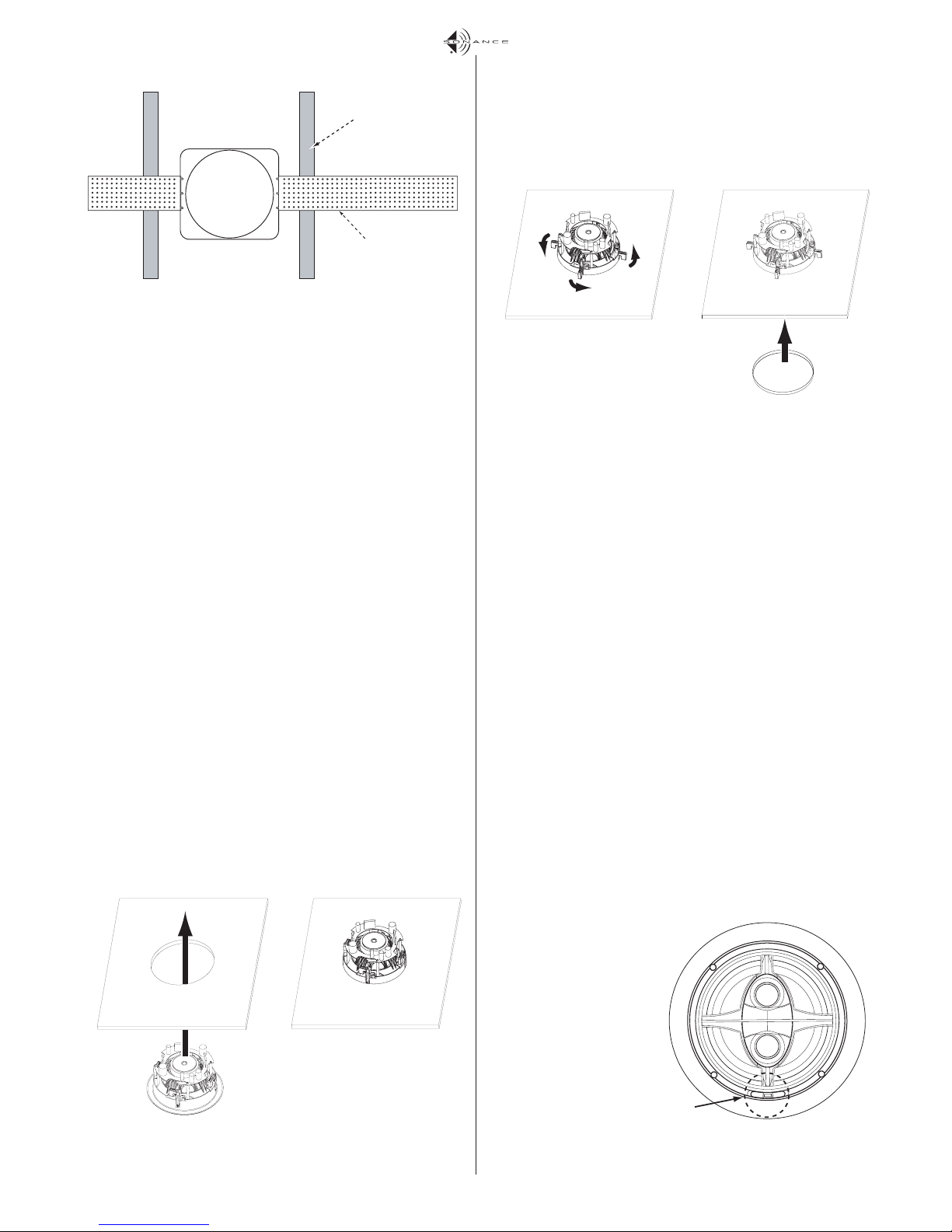
7. Make sure all the RotoLock clamps are in the full clockwise position
so that they are tucked within the cutout border. Insert the speaker
into the hole in the ceiling.
Note: The RotoLock system can accommodate a maximum wall or
ceiling material thickness of 1
3
/8”.
8. Tighten the four screws on the front of the speaker baffle. The
RotoLock clamps will automatically rotate into position and begin
clamping the speaker.
• When you notice resistance on the four screws the speaker has been
clamped successfully.
The speaker flange is designed to flex and conform to any small
imperfections in the wall surface. Do not tighten the screws so much
so that the flange bows-out.
Important: Always use low-torque settings — NEVER over-tighten.
9. Attach the grille after the speaker has been installed. Insert about half
of the grille into the groove at the edge of the speaker. Gently fit the
remaining half of the grille by working around the speaker, fitting the
grille into the groove as you go.
Note: You can adjust the torque applied to the RotoLock screws to
achieve a proper grille fit.
PAINTING THE SPEAKERS AND GRILLES
You can paint the speaker and grille before installing it, which will
eliminate the “paint scar” if the speaker ever needs to be removed for
service. You can also paint the speakers after installation, but before the
grilles are attached. All Symphony speakers come from the factory fitted
with a plastic ‘paint plug’. Use the paint plug to protect the speaker
drivers while the flange is being painted along with the wall.
Sonance always suggests painting the grille separately from the speaker.
Before painting, carefully remove the under-grille cloth. It is held in place
with a light tacking glue that makes it easy to remove.
Spray the grilles with thinned paint (5 parts thinner to 1 part paint),
being careful not to plug the holes. Too heavy a coat of paint on the grille
will adversely affect the sound of the speaker.
Once the grilles and flange are painted and dry, replace the under-grille
cloth, remove the paint plug from the speaker flange and install the grille.
ADJUSTING YOUR SPEAKERS
Tweeter Level Control (S623SSTRonly)
The Symphony S623SSTRhas a tweeter level control switch that lets you
boost or cut the tweeters’ level by 3dB.
Once you have installed the
speaker, listen to a variety of
music that you are familiar
with. If the music all tends to
sound too bright, adjust the
level control to the -3dB position. If the music all tends to
sound too dull, adjust the level
control to the +3dB position.
If some recordings sound dull
and some sound bright, the
speaker is accurately reproducing differences in the
recordings, and you should
leave the control in the 0dB
position.
Step 7:
Illustration 1: Symphony FlexBracket Installation
Step 8:
Step 9:
T
Illustration 2: Tweeter Level Control
Ceiling Joist
FlexBracket Wing
weeter
Level
Control
 Loading...