

INTRODUCTION
PN. 33-2855
I N S T A L L A T I O N I N S T R U C T I O N S
SONANCE SYMPHONY EXTREME T
2 - CHANNEL AUDIO PLACEMENT
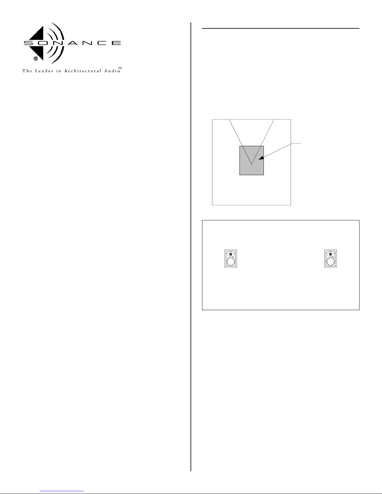
For best performance, the center of the Sonance Symphony Extreme
XT speakers should be placed around ear level. This would be
approximately 40" for a seated listener and 62" for a standing listener.
The distance from the listener to the speakers and the distance
between the speakers should be the same, see diagram. Distance A, B
and C should be the same.
Thank you for purchasing Sonance Symphony Extreme T in-wall
speakers. When properly installed, this product will provide you with
years of entertainment pleasure.
To obtain the full potential of your new speakers, please read all
instructions before starting the installation. If you do not have the
necessary skills to install the speakers yourself, contact your authorized
Sonance dealer for installation options.
PARTS LIST
Each Extreme T speaker package includes the following items:
(2) Sonance Extreme XT speakers
(2) Paintable grilles
(2) Plastic paint plugs to protect speakers during painting
(1) Mounting cutout template ( in packaging )
OPTIONAL ACCESSORIES
New Construction Bracket - part number 90-0700
Plastic template to reserve hole in new construction.
A
CB
Ideal Listening Zone
FlexBracket - part number 90-1193
Plastic template to reserve hole in new construction.
Designed to be used with the FlexbarJ mounting system.
Staple Template - part number 90-0651
Thin plastic template for new construction to reserve hole in
new construction. Designed to be used with the FlexbarJ
mounting system.
Coverplate - part number 90-0693
Designed to cover hole made by FlexBracket, New
Construction Bracket or Staple Template until the speaker is
installed.
Acoustic Enclosure - part number 91687
A 3/4" medium density fiberboard enclosure designed
specifically for the C and Symphony series speakers.
Fire Rate Back Can - part number 91709
A metal can designed for the C and Symphony series
speakers that meets the following fire testing criteria;
ASTM E119, CAN/ULC S101, NFPA 251, UBC 7-1, UL 263.
ENVIRONMENTAL SPECIFICATIONS
Maximum Heat
104 degrees C = (220.0 degrees Fahrenheit)
Maximum Cold
-40 degrees C = (-40.0 degrees Fahrenheit)
Maximum Humidity and Temperature
99% humidity @ 49 degrees C = (120.0 degrees Fahrenheit)
95% humidity @ -40 degrees C = (-40.0 degrees Fahrenheit)
The Extreme speakers meet or exceed the following:
Salt Spray - ASTM-B117
UV Test - ASTM-G23H
IEC / CEE Water Splashing Test - IP-X4
Vibration Test - ASTM D5112-98 and ASTM D3580-95
1
WIRE GAUGE AND QUALITY
The total wire resistance should be less than 10% of the speaker
impedance. If using an 8 ohm speaker, your total wire resistance
should be no more than 0.8 ohms.
In simple terms, the extra resistance from the wire will have a very
negative effect on the sound quality of the speaker. The sound can be
less dynamic, definition of bass frequencies can be reduced, and in
extreme cases, the high frequencies can be attenuated. Amplifier
power is also wasted in the wire, reducing the maximum output level
of the system.
Please refer to the following chart when deciding on the appropriate
wire gauge for your installation.
Wire resistance in Ohms vs. length of cable run
Distance in Feet
20 gauge
18 gauge
16 gauge
14 gauge
12 gauge
10 gauge
50' 100' 150' 200' 250' 300'
5.18
4.32
3.45
1.73
1.30
.85
.54
.34
.22
2.59
1.94
1.28
.81
.51
.33
2.59
1.71
1.08
.68
.44
3.24
2.14
1.35
.85
.56
3.89
2.56
1.62
1.02
.67
.86
.65
.43
.27
.17
.11
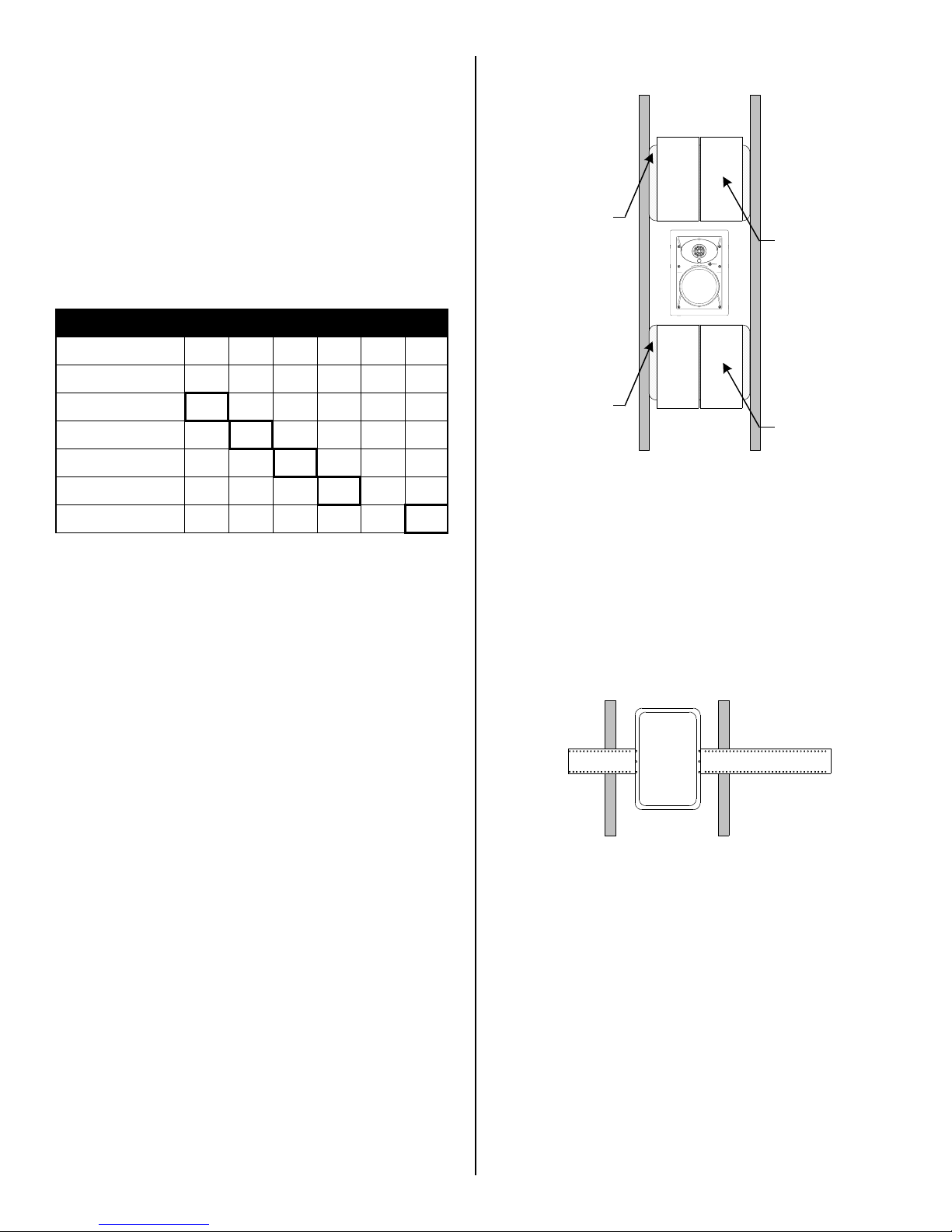
PREPARING THE INSTALLATION LOCATION
Acoustic Pillow
Damping Tiles
Acoustic Pillow
Damping Tiles
The Sonafill System
New Construction
The Extreme XT speakers feature an integral Rotolock mounting
system for quick mounting into walls. The Symphony / C series
FlexBracket and New Construction Bracket are only necessary in new
construction installations when reserving a location for the speaker is
desired.
All Sonance speakers are designed to be relatively insensitive to
changes in enclosure volume. To achieve the ultimate performance
from the Extreme XT speakers, a section of the stud bay can be
sectioned off to form a back box. Building this enclosure will create a
dramatic improvement in the quality of bass response and power
handling.
Back box volume requirements:
Insulating the wall cavity
Speaker performance can be enhanced by insulating the cavity with
fiberglass insulation.
When installing speakers in a wall, it is best to insert a sheet of
unfaced fiberglass insulation above and below the speaker.
To further improve the sound quality, install insulation in the bays
adjacent to the speaker location. This will reduce noise produced by
the unsupported drywall.
Sonafill
Sonafill is a retrofitable acoustical treatment for loudspeakers that
virtually eliminates the noise produced by resonating drywall and
dramatically improves mid-bass sound quality. Sonafill also reduces
room-to-room noise especially in multi-channel installations where
many speakers are installed.
The Sonafill system consists of two pillows and four tiles. Installation is
accomplished by first adhering the tiles to the inside of the cavity, then
stuffing the two pillows in place behind the tiles.
Extreme XT 1.00 cubic feet (28.3 liters)
®
The FlexBracket and New Construction Bracket will serve as a guide for
the drywaller when cutting holes for in-wall speakers. The FlexBracket
or New Construction Bracket is nailed or screwed to the studs so that
the hole is in the desired location once the drywall is installed.
Symphony / C series FlexBracket
Retrofit
With the Flexbar system, the speaker can be installed directly into
existing walls. Once the hole is cut and the cable is run, the speakers
can be installed in a matter of seconds.
Once you have determined the area you would like to locate your
speakers, you will need to do an obstruction survey. Before you cut the
hole for the speaker, be certain no studs, conduit, pipe, heating duct
or air return will interfere with the speaker.
The cutout for the Extreme XT is 6 3/4" (171mm) x 11" (279mm).
There must also be 2-1/2" (63.5mm) of depth within the wall for the
speaker.
A cut out template is provided in the packaging of the speaker.
Position the template where the speaker is to be located and pencil an
outline on the wall. If you are unsure about obstructions, drill a small
hole in the center of the cutout and insert a coat hanger into the hole
to feel for possible obstructions. If no obstructions are found, proceed
with cutting the hole using a drywall saw and run the speaker wires.
2
 Loading...