

1
Introduction
Thank you for purchasing Sonance Visual Performance
®
Single-Stereo Technology®(SST) or surround (SUR) speakers.
When properly installed your new speakers will give you years
of entertainment pleasure.
Box Contents
Item Quantity (SST) Quantity (SUR)
Visual Performance Speaker 1 2
Paintable Grille 1 2
Plastic Paint Plug 1 2
Mounting Cutout Template 1 1
Speaker Placement
SST Models
Because a single SST speaker reproduces both stereo channels
from a single location, it will deliver outstanding performance
from a wide variety of mounting locations where a pair of stereo
speakers would be impractical, including hallways, bathrooms
and closets.
The table below shows how far apart SST speakers can be
spaced in distributed audio applications while still providing
good coverage for standing and seated listeners (see
Figure 1
).
Ceiling Height Spacing (Standing) Spacing (Seated)
9-Foot Ceiling 5’7” (1.7m) 9’5” (2.9m)
10-Foot Ceiling 9’7” (3.0m) 13’5” (4.1m)
12-Foot Ceiling 13’7” (4.2m) 17’5” (5.3m)
14-Foot Ceiling 17.7’ (5.4m) 21’5” (6.6m)
SUR Models:
5.1-Channel Home Theater System
Mount the left and right surround speakers on the ceiling 2 – 6
feet (0.6m – 1.8m) behind the listening position. The speakers
should be 6 – 10 feet (1.8m – 3m) apart. Orient the speakers so
the tweeters face the front and rear walls of the room. Use
Figure
2
as a guide.
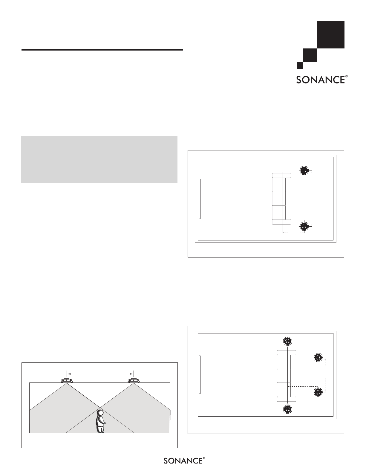
SUR Models:
7.1-Channel Home Theater System
Mount the left and right surround speakers directly to the sides of
the listening position, 6 – 10 feet (1.8m – 3m) apart. Mount the
surround back speakers 2 – 6 feet (0.6m – 1.8m) behind the
listening position. The surround back speakers should be closer
together than the left and right surround speakers, 3 – 6 feet
(0.9m – 1.8m) apart. Use
Figure 3
as a guide.
TV
3' – 6'
(0.9m – 1.8m)
apart
2' – 6'
(0.6m – 1.8m)
Surround
Back
Speaker
Surround
Back
Speaker
Right Surround
Speaker
Left Surround
Speaker
FIGURE 3: SUR SPEAKER PLACEMENT IN A 7.1-CHANNEL SYSTEM
INSTRUCTION MANUAL
VISUAL PERFORMANCE® SERIES
SST AND SUR SPEAKERS
TV
6' – 10'
(1.8m – 3m)
apart
2' – 6'
(0.6m – 1.8m)
Right Surround
Speaker
Left Surround
Speaker
FIGURE 2: SUR SPEAKER PLACEMENT IN A 5.1-CHANNEL SYSTEM
C
OVERAGE
A
REA
C
OVERAGE
A
REA
S
PEAKER
S
PACING
FIGURE 1: DISTRIBUTED AUDIO SPEAKER SPACING
S
AFETYWARNING
:
THESE SPEAKERS HAVE FASTMOUNT
®
TABS THAT PREVENT THE
SPEAKER FROM FALLING OUT OF THE MOUNTING HOLE DURING THE
INSTALLATION PROCESS
.
T
HE EDGES OF THEFASTMOUNT TABS ARE VERY SHARP
.
U
SE CAUTION WHEN HANDLING THE SPEAKER
.

SONANCE VISUAL PERFORMANCE®SST & SUR
Before Installation: Retrofit
1. Determine the location for the speaker (see
Placement
, on page 1).
2. Per form an obstruction survey to be certain that there are no
studs, conduit, pipes, heating ducts, pocket doors or air returns
in the wall or ceiling cavity that will interfere with the speaker.
3. M
ounting space r e q u i r e m e n t s :
• La r g e ro u nd S S T & SU R : 10
cut-out; 5
arge s q u a r e SS T : 10¼" x 10¼" (260mm x 260mm)
• L
cut-out; 5
edium round S S T & S U R : 8¼" (210mm) diameter
• M
7
⁄8" (149mm) depth within the mounting cavity.
7
⁄8" (149mm) depth within the mounting cavity.
1
⁄8" (257mm) diameter
cut-out; 4¾" (121mm) depth within the mountinig cavity.
• M
edium s q u a r e SST: 8¼" x 8¼" (210mm x 210mm)
cut-out; 4¾" (121mm) depth within the mounting cavity.
edium rectangle SST: 6
• M
cut-out; 3
edium T h i n L i n e ro u n d SST: 8¼" (210mm) diameter
• M
cut-out; 3
ma l l ro un d SST: 57⁄8" (149mm) diameter cut-out;
• S
9
⁄16" (91mm) depth within the mounting cavity.
1
⁄32" (77mm) depth within the mounting cavity.
15
⁄16" x 10¾" (176mm x 273mm)
3 7/8" (97mm) depth within the mounting cavity.
• S
mall square S S T : 5
5
⁄8" x 55⁄8" (143mm x 143mm)
cut-out; 3 7/8"" (97mm) depth within the mounting cavity.
4. Position the included cut-out template where the speaker is to
be located and pencil an outline on the wall or ceiling. If you
are unsure about obstructions, drill a small hole in the center
of the outline and insert a coat hanger wire into the hole to
feel-around for possible obstructions.
5. Cut the mounting hole using a keyhole or drywall saw, and
run the speaker wires from the mounting hole to the amplifier
location.
NOTE : CONSULT LOCAL BUILD ING COD ES BEFORE RUNNING
SPEAKER WIRES TH ROUGH CEILINGS .
Speaker
Installation
Visual Performance SST AND SUR speakers feature exclusive
FastMount tabs and an integral Roto-Lock
quick mounting directly into existing walls and ceilings.
®
mounting system for
5. Make sure all the RotoLock clamps are in the
full clockwise position
so that they are tucked
within the mounting
hole’s border. Insert the
speaker into the hole in
th e wa ll or ceiling
(
Figure 4
). The RotoLock system can accommoda te a maximum
wall or ceiling material
th ickness of 1¼”
(32mm).
The FastMount tabs
will prevent the speaker from falling out of
the mounting hole,
Roto-Lock Clamps
(retracted)
FIGURE 4: INSERT SPEAKER INTO
MOUNTING HOLE
allowing the installer
to let go of the speaker
to pick-up tools o r
other items (
Figure 5
).
FastMou nt Tabs
NOTE: THE FASTMOUNT
TABS ARE DESIGNED FOR
ON E-TIM E USE ON LY.
IF THE SPEAKER IS
RE MO VE D FROM THE
MOUNTING HOLE THE
FASTMOUNT TABS WILL
DI SCONNECT AND
REMAIN INSIDE THE WALL
OR CEILING.
6. Tighten the four screws on the front of the speaker baffle
(
Figure 6
). The Roto-Lock clamps will automatically rotate into
position and begin clamping the speaker. When you notice resistance on the screws the speaker has been clamped successfully.
FIGURE 5: FASTMOUNT TABS
WARNING: The edges of FastMount tabs are very
sharp. Use caution when handling the speaker.
1. Remove the paint plug from the speaker.
2. Run speaker wire from each speaker to the amplifier location.
3. Strip ¼” – ½” (6mm – 12mm) of insulation from each speaker lead. Twist the
to ensure that there are no stray strands. (Stray strands that
touch each other can cause a short-circuit that can damage
the amplifier.)
4. The speaker’s connector posts are spring-loaded. Push the top
of each connector post down to open the connector and inser t
the exposed wires into the holes in the posts.
• The speaker’s positive post is labeled with a red dot; the negative post is labeled with a black dot. Double-check that you
connected amplifier “+” to speaker “+” and amplifier “–” to
speaker “–”.
2
strands or tin the exposed wire with solder
Roto-Lock
Screws
Roto-Lock
Screws
FIGURE 6: TIGHTENING THE ROTO-LOCK SCREWS
 Loading...