

Page 1

Introduction
The SS6 and SS4 let you connect multiple pairs of loudspeakers to one receiver or amplifier and have all sets of speakers active
at one time. The SS6 lets you connect up to six pairs of speakers; the SS4 lets you connect up to four. Each pair of speakers can
be turned ON and OFF independently.
Where to Place the Speaker Selector
For optimum performance, the speaker selector should be placed close to your receiver/amplifier.
If you place the selector in an enclosed cabinet or between shelving, make sure there is adequate space (at least two inches)
between the top of the selector and any shelving, cabinetry, or components placed above it.
DDoo nnoott ppll aaccee tt hhee ssppeeaakkeerr
ss eelleeccttoorr oo nn tt oo pp oo ff oo rr nnee aa rr ppllaasstt iicc oorr ccoommbbuuss ttii bb llee mm aatt eerr iiaall ..
Connecting the Speaker Selector to the Amplifier
IImmppoorrttaanntt::
TTuurrnn
tthhee
rreecceeiivveerr’’ss
oorr
aammpplliiffiieerr’’ss
ppoowweerr
OOFFFF
bbeeffoorree
mmaakkiinngg
aannyy
ccoonnnneeccttiioonnss
ttoo
tthhee
sseelleeccttoorr..
Use 16-gauge (or larger) speaker cable like Sonance MediaLinQ Gold or Bronze 16/4 speaker wire to connect the amplifier to
the selector.
1. Strip ¼” – ½” of insulation from each speaker lead. Twist the strands to ensure that there are no stray strands.
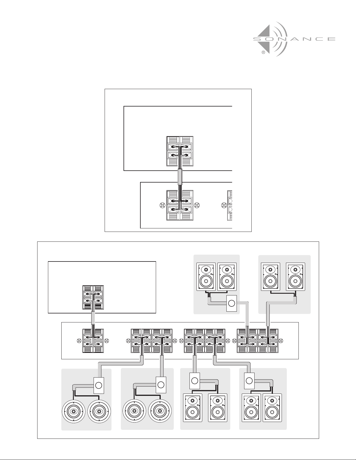
2. Connect the speaker leads between your amplifier’s speaker outputs and the input terminals on the back of the speaker
selector (see
Figure 1
, on page 3). To avoid a short-circuit that can damage your receiver or amplifier, be sure no stray
strands of wire touch each other or the chassis’ of the selector or amplifier.
Note: Double check the polarity of the speaker wires for each channel: Amplifier “+” to Selector “+”
and Amplifier “–” to Selector “–”.
Connecting the Speaker Selector to Speakers
IImmppoorrttaanntt::
TTuurrnn
tthhee
rreecceeiivveerr’’ss
oorr
aammpplliiffiieerr’’ss
ppoowweerr
OOFFFF
bbeeffoorree
mmaakkiinngg
aannyy
ccoonnnneeccttiioonnss
ttoo
tthhee
sseelleeccttoorr..
Use 16-gauge (or larger) speaker cable. It is easiest to run 4-conductor cable (for example, Sonance MediaLinQ gold or
Bronze 16/4 speaker cable) from each stereo pair of speakers to one of the speaker outputs on the back of the speaker
selector (see ‘Room 1’ in Figure 2 , on page 3).
1
CAUTION
UUnnddeerr
nnoorrmmaall
ooppeerraattiinngg
ccoonnddiittiioonnss
tthhee
ssppeeaakkeerr
sseelleeccttoorr
wwiillll
bbeeccoommee
wwaarrmm..
IIff
nnoott
uusseedd
pprrooppeerrllyy
tthhee
uunnddeerrssiiddee
ooff
tthhiiss
uunniitt
ccaann
bbeeccoommee
eexxttrreemmeellyy
hhoott..
DDoo
nnoott
ooppeerraattee
tthhee
sseelleeccttoorr
wwiitthh
aann
aammpplliiffiieerr
tthhaatt
eexxcceeeeddss
tthhee
MMaaxxiimmuumm
AAmmpplliiffiieerr
PPoowweer
rraattiinnggss
ddeessccrriibbeedd
iinn
tthhee
SSppeecciiffiiccaattiioonnss sseeccttiioonn
oonn
ppaaggee
22..
TToo
eennssuurree
ssaaffee
oop
ffoollllooww
aallll
ooff
tthheessee
iinnssttrruuccttiioonnss
ccaarreeffuullllyy::
••
DDoo
nnoott
ppllaaccee
tthhee
sseelleecctto
oonn
ttoopp
ooff
oorr
nneeaarr
ppllaassttiicc
oorr
ccoommbbuussttiibbllee
mmaatteerriiaall..
••
DDoo
nnoott
ppllaaccee
ootthheerr
ccoommppoonneennttss
ddiirreeccttllyy
oonn
ttoopp
ooff
tthhee
sseelleeccttoorr..
••
DDoo
nnoott
ppllaaccee
tthhee
sseelleeccttoorr
iinn
aann
eenncclloosseedd
ccaabbiinneett
wwiitthhoouutt
pprroovviiddiinngg
aaddeeqquuaattee
vveennttiillaattiioonn..
SS6 and SS4 Speaker Selector
Installation Instructions
Page 2

2
Adding Speaker Volume Controls
We recommend that you connect all your speakers to in-wall volume controls (like the Sonance VC60S/R) and then to the
speaker selector (see
‘Rooms 2 – 6’ inFigure 2
, on page 3). This gives you independent volume balancing and control in all
speaker locations: Your receiver's volume control acts as the Master Volume, and each individual pair of speakers can be
either OFF, or ON at its own volume level, independent of the other speakers connected in the system.
Protecting the Amplifier
The speaker selector includes a Protection switch located underneath the selector, on the right side. To protect your receiver
or amplifier Sonance strongly recommends that you leave the Protection switch engaged at all times. Always operate your
receiver or amplifier within its rated power range and within the power range of the speaker selector.
• To ENGAGE the Protection circuit, slide the red switch towards the
back
of the selector.
• To DISENGAGE the Protection circuit, slide the red switch towards the
front
of the selector.
IImmppoorrttaanntt::
TTuurrnniinngg
tthhee
pprrootteeccttiioonn
sswwiittcchh
OOFFFF aalllloowwss
ggrreeaatteerr
ppoowweerr
ttoo
yyoouurr
ssppeeaakkeerrss,,
bbuutt
mmaayy
ddaammaaggee
yyoouurr
rreecceeiivveerr//aammpplliiffiieerr..
Automatic Internal Fuse
The SS6 and SS4 have an internal fuse that will disconnect all of the speakers if the current draw through the unit exceeds a safe
level. After the current draw returns to a safe level the fuse will automatically reset and re-connect all of the speakers.
IImmppoorrttaanntt:: IIff
tthhee
ssppeeaakkeerr
sseelleeccttoorr
ccoonnttiinnuuaallllyy
ttuurrnnss
tthhee
ssppeeaakkeerrss
OOFFFF
aanndd
OONN,,
oonnee
oorr
mmoorree
ooff
tthhee
ffoolllloowwiinngg
uunnssaaffee
ccoonnddiittiioonnss
eexxiissttss
iinn
tthhee
aauuddiioo
ssyysstteemm::
• The amplifier’s volume is set too high.
• The amplifier’s power output exceeds the Maximum Amplifier Power ratings as described in the
Specifications
section below.
• There is a short-circuit in one or more of the speaker wires.
TToo
eennssuurree
ssaaffeettyy,,
ccoorrrreecctt
aannyy
aanndd
aallll
ooff
tthheessee
ccoonnddiittiioonnss
bbeeffoorree
ooppeerraattiinngg
tthhee
aauuddiioo
ssyysstteemm
aaggaaiinn..
Specifications:
Power Handling:
MM aa xxiimm uu mm AAmmppll iiffii eerr PP oo wwee rr wwiitt hh PP rrootteecc ttii oo nn cciirrcc uu iitt EENN GG AAGG EE DD aanndd AALLLL pp aa iirr ss ooff ss ppeeaakk eerr ss ooppee rraatt iinngg::
40 watts RMS per channel
MM aa xxi
120 watts RMS per channel
Protection Circuitry: Resistive in-line
Switch Type: Slide-slide, self-cleaning
Frequency Response: 20Hz – 20kHz
Dimensions (W x H x D): SS6 — 11¼” x 2” x 7” (286mm x 51mm x 178mm)
SS4 — 8½” x 2” x 7” (216mm x 51mm x 178mm)
SS6 and SS4 Speaker Selector
Installation Instructions
Page 3
3
LR
LRLR LR LRLR LRLR
INPUT SPEAKER 6 SPEAKER 5 SPEAKER 4 SPEAKER 3 SPEAKER 2 SPEAKER 1
LR
+
–
+
–
+
–
+
–
+
–
ROOM 5
ROOM 6
ROOM 3ROOM 4
Volume Control
Volume Control
Speaker
Outputs
Amplifier/
Receiver
SS6
Volume Control
Volume Control
Volume Control
ROOM 2
ROOM 1
Figure 2: Connecting the Selector to Speakers (SS6 Shown)
Figure 1: Connecting the Selector to The Amplifier
LR
LR
INPUT S
LR
+
–
+
–
Speaker
Outputs
Amplifier/
Receiver
SS6
SS6 and SS4 Speaker Selector
Installation Instructions
Page 4
 Loading...