

MAG CONCEALED TV
AUDIO SYSTEM
INSTRUCTION MANUAL
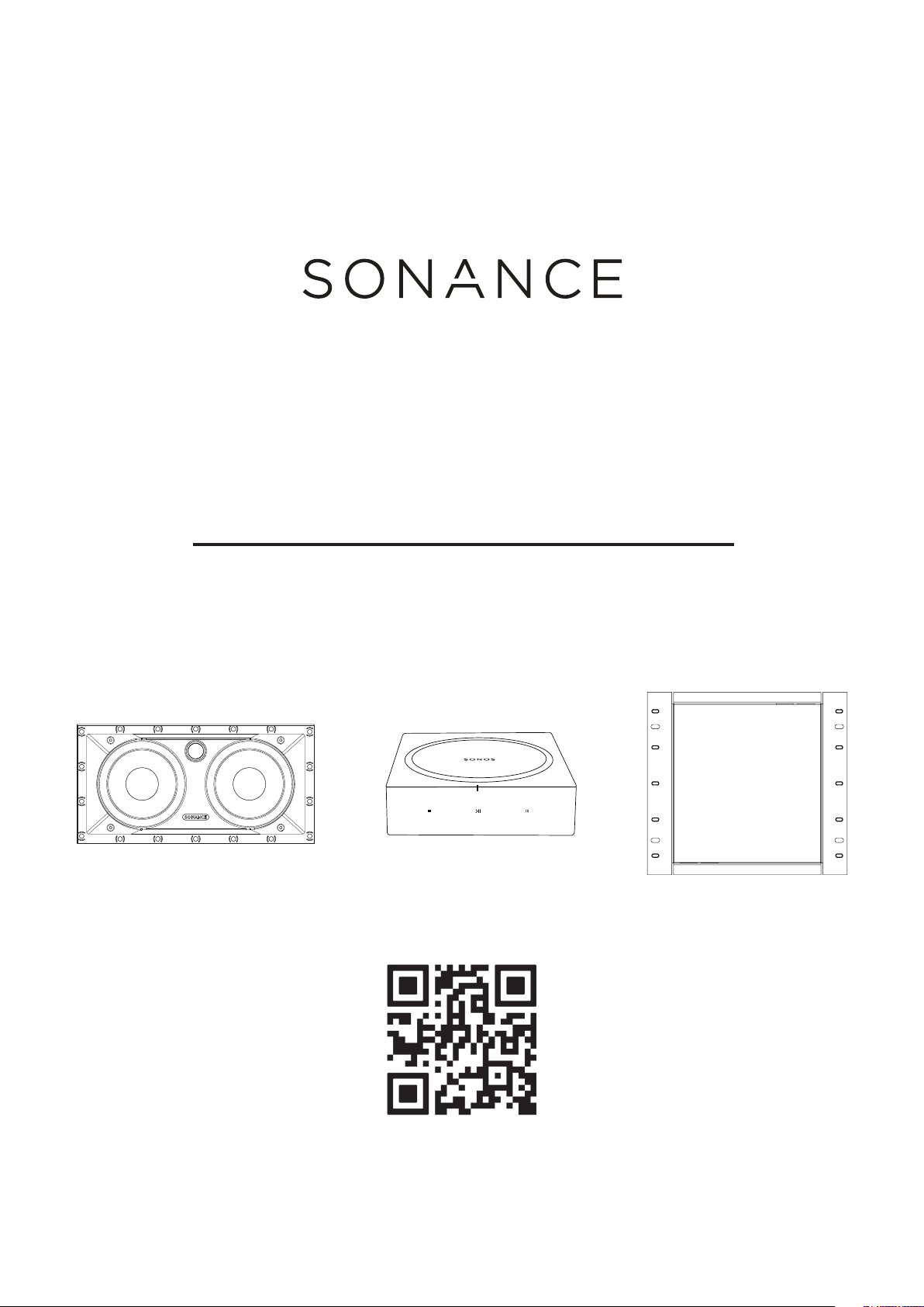
MAG6 LCR | SONOS AMP | SONANCE TV Box
Scan QR code
for setup video
INSTRUCTION MANUAL
MAG CONCEALED TV
AUDIO SYSTEM
IMPORTANT SAFETY INFORMATION
You should always follow these basic safety precautions when
using your Sonance MAG Concealed TV Audio System, to reduce
the risk of fire, electric shock, and injury to persons:
1. Read and retain instructions: Read all the safety and operating
instructions before operating the amplifier, and retain them for
future reference.
2. Heed warnings: Adhere to all warnings and precautions listed
on the amplifier and in the operating instructions.
3. Follow instructions: Follow all
operating instructions.
4. Water: Never use the amplifier next to water.
5. Carts and stands: The amplifier should be
used only with a cart or stand that is recommended by the
manufacturer. An amplifier and cart combination should be
moved with care.
6. CAUTION: TO PREVENT ELECTRIC SHOCK, DO NOT USE THE
POLARIZED PLUG WITH AN EXTENSION CORD, RECEPTACLE,
OR OTHER OUTLETS UNLESS THE BLADES CAN BE FULLY
INSERTED TO PREVENT BLADE EXPOSURE.
7. Ventilation: The Subwoofer should be situated so that its
location or position does not interfere with its proper ventilation.
For example, the subwoofer should not be situated on a bed,
sofa, rug, or similar surface that may block the ventilation
openings; or be placed in a built-in situation, such as a book case
or a cabinet, that may impede the flow of air over the subwoofer.
• The amplifier has been exposed to rain.
• The amplifier does not appear to operate normally or exhibits a
marked change in performance.
• The amplifier has been dropped, or the enclosure damaged.
16. Servicing: The user should not attempt to service the
amplifier beyond that described in the operating instructions. All
other servicing should be referred to qualified service personnel.
17. Lifting: Improper lifting of the 28 lbs. MS10 SUB can cause
personal injury.
18. Power requirement: Do not connect the Subwoofer to the
accessory outlet of any other component. A minimum 15 amp
(20 amp preferred) grounded wall outlet is required.
WARNING: THE POWER (MAINS) PLUG SERVES AS THE
AMPLIFIER’S DISCONNECT DEVICE. THE DISCONNECT DEVICE
SHALL REMAIN READILY OPERABLE DURING OPERATION.
TO ENSURE THAT THE DISCONNECT DEVICE (POWER PLUG)
IS EASILY ACCESSIBLE, THE USER SHALL NOT PLACE THE
AMPLIFIER IN A CONFINED AREA DURING OPERATION.
19. Storms: To prevent damage to components, unplug all
electronic equipment during thunderstorms.
8. Heat: Situate the amplifier away from heat sources such
as radiators, stoves, or other appliances (including external
amplifiers) that produce heat.
9. Grounding or polarization: Grounding or polarization are
precautions that should be taken so that these attributes are
not defeated.
10. Power-cord protection: Route power supply cords so that
they will not be walked on or pinched by items placed on or
against them.
11. Cleaning: To clean the amplifier, use “canned air” or wipe
the amplifier with a soft cloth. Do not use solvents, as they may
damage the amplifier.
12. Non-use periods: Unplug the amplifier’s power cord from
the outlet when the amplifier will be left unused for a long period
of time.
13. Object entry: Care should be taken so that objects do not fall
through the opening of the enclosure.
14. Moisture: Do not expose the amplifier to dripping or
splashing. Do not place objects filled with liquids, such as vases,
on the amplifier.
15. Damage requiring service: Have the amplifier serviced by a
qualified service personnel when:
• The power supply cord or the plug has been damaged.
NOTE: SONANCE RECOMMENDS USING BEST BUY’S
PROFESSIONAL INSTALLATION SERVICE FOR ANYONE
NOT FAMILIAR WITH THE PROCESS OF RETROFITTING
LOW VOLTAGE WIRING
• Objects have fallen, or liquid has been spilled into the amplifier.
2
INTRODUCTION
Centered Oset
Sonancet TV Box installs behind your TV
Outline indicates your TV
Sonance TV Box installs behind your TV
Outline indicates your TV
Thank you for purchasing MAG Concealed TV Audio System.
When properly installed your new speakers will give you
years of entertainment pleasure.
BOX CONTENTS
MAG Concealed TV Audio System box contains:
(2) MAG6 LCR Speakers
(1) SONOS AMP
(1) SONANCE TV Box and Mounting Bracket
(2) SONANCE TV Box Spacers
(1) Power Bridge ONE-CK Power Wall Box
(1) Power Strip with USB
(1) Mounting Screws and Velcro Kit
(2) Wire Grommets
TOOLS NEEDED:
1. Electric Screw Driver
2. Tape Measure
3. Level
4. Stud Finder
5. Drywall Saw
6. Wire Strippers
7. Pencil
TOOLS RECOMMENDED:
1. Steel Fish Tape or Fish Rods
2. Hole Saw or Spade Bits
NEEDED ITEMS:
1. Speaker Wire
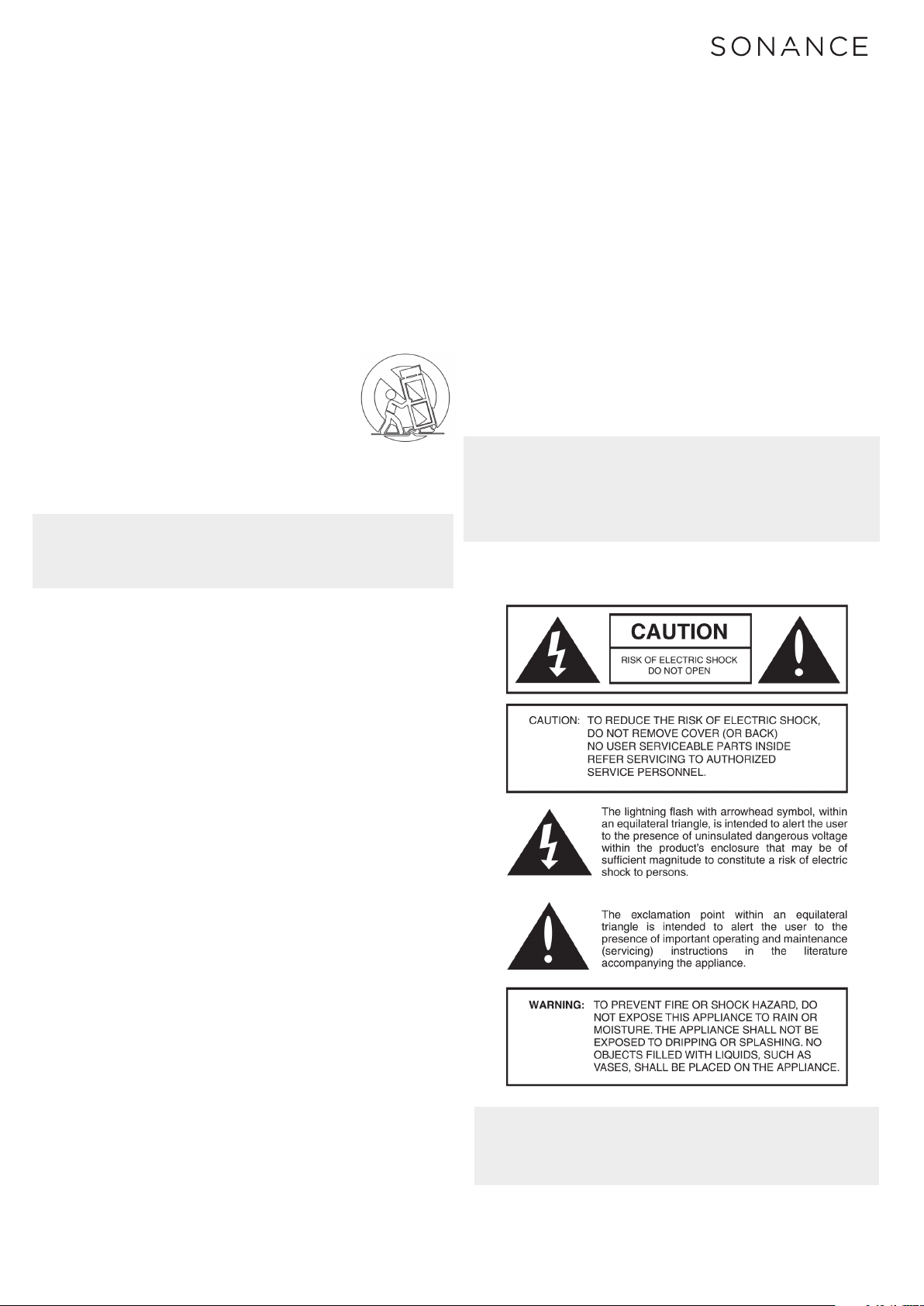
MAG PREMIUM SPEAKER PLACEMENT
MAG6 LCR - Left & Right Speakers
1. Place the left and right speakers 6 – 10 feet (1.8m – 3m) apart
from each other. SONANCE recommends installing the center
of the speakers as close to the center the TV, ideally at ear
level when seated. See Figure 1
2. The main listening position should be 4 – 15 feet (1.2m – 4.5m)
away from the speakers and TV.
3. Once you have identified the desired mounting location
and have checked for obstructions, use the included cutout
template and a level to mark the cut lines for the speaker
mounting hole. Then, cut the mounting hole using a drywall
saw, see the template provided with the speakers for cut
out dimensions.
Left and Right
LCR Speakers
6’-10’
(1.8m - 3m)
Apart
TV
Overhead View
BEFORE INSTALLATION
Determine the location for the speakers and Wall Box
(see before you begin below).
Perform an obstruction survey using a stud finder to be
certain that there are no studs, conduit, pipes, heating,
ducts, pocket doors or air returns in the wall cavity that
will interfere with the speaker or SONANCE TV Box.
If you are unsure about obstructions, drill a small hole in
the center of the outline and insert a coat hanger wire
into the hole to feel around for possible obstructions.
NOTE: CONSULT LOCAL BUILDING CODES BEFORE RUNNING
AC WIRES AND SPEAKER WIRES THROUGH WALLS.
BEFORE YOU BEGIN
Plan your layout of your TV, TV bracket, SONANCE TV Box
and Speakers before cutting any holes.
1. IMPORTANT: Determine the final location where you want
your TV when the install is complete, this will determine
were you place the TV bracket, SONANCE TV Box and
the Speakers.
2. Once you have determined the final install location of where
your TV will be installed measure and mark o with tape the
top and the bottom of where the TV will be installed.
3. Measure from the top and bottom of the marked location to
determine the center location of the TV when mounted and
mark the center location with tape on each side of the TV.
4. Install the TV bracket arms onto the TV, measure and
determine where to mount the TV braket so the TV hangs
in the final location you have previously measured in step
2. Mark the location of the TV bracket.
5. Once you have determined where your TV bracket will
be installed, determine if the SONANCE TV Box will
be installed above or below the TV bracket to best
conceal the SONANCE TV Box but still allows access to
electronics when the TV is installed.
6. Mark the location of the SONANCE TV Box.
7. For more assistance; watch the setup videos by scanning
the QR code on the front cover.
4’-15 From Speakers
Figure 1
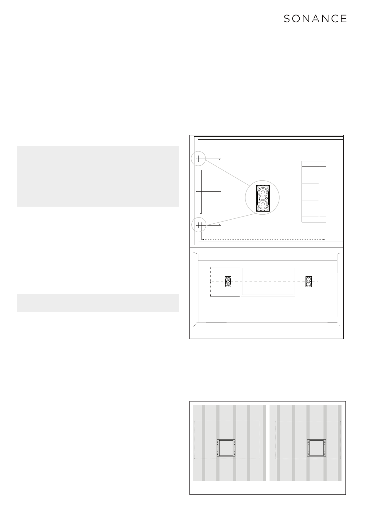
SONANCE TV BOX PLACEMENT
SONANCE TV Box (Figure 2)
• Determine The center location of your television first.
• The SONANCE TV Box is designed to be installed between
two studs. If the center of your TV Covers a stud, position the
SONANCE TV Box to the left or right of the center stud.
Figure 2
3

• The SONANCE TV Box is designed to be installed “Above or
14 IN
[355.6 mm]
Install Option 1
Install Option 2
Roto-Lock
Clamps
(retracted)
below your TV Bracket easy access to the contents inside
the box.
• After you have determined the center location of your
television, and have determined where your TV bracket
will be installed, you can now move onto determining the
location of the Sonance TV Box. See Figure 3 for positioning
ideas for the The SONANCE TV Box.
Figure 3
SONANCE TV BOX INSTALLATION
1. Determine the center location of your TV first. Use a
stud finder to locate the space in-between two studs
that are as close to the center of your TV as possible.
2. Mark the two studs on each side of the location
determined to mount the wall box. It is recommended
to mound the wall box as close to the center of the TV
as possible. Measure between the two marked studs to
confirm that the SONANCE TV Box will fit (width >= 13”).
3. Use a drywall saw to cut a hole 13 Inches wide and 14
inches tall to mount the SONANCE TV Box.
4. Test fit the SONANCE TV Box into the opening that was
just cut and make any needed modifications to the opening
at this time.
5. DO NOT SECURE THE SONANCE TV BOX WITH
SCREWS AT THIS POINT. CONTINUE TO
INSTALLATION OF MAG6 LCR BELOW.
Sonance speakers feature integral Roto-Lock
®
mounting
system for quick mounting directly into existing walls.
1. Fish speaker wire through the wall into the SONANCE
TV Box openings using one of the provided knock outs if
needed. This needs to occur before the speaker is in place.
2. Strip 1/4” – 1/2” (6mm – 12mm) of insulation from each
speaker wire. Twist the strands or tin the exposed wire
with solder to ensure that there are no stray strands.
NOTE: STRAY STRANDS THAT TOUCH EACH OTHER CAN
CAUSE A SHORT-CIRCUIT THAT CAN DAMAGE THE AMPLIFIER.
3. The speaker’s terminals are spring-loaded. Push the top of
each terminal down to open the connector and insert the
exposed wires into the holes in the spring terminals. The
speaker’s positive spring terminal is labeled with a red dot;
the negative spring terminal is labeled with a black dot.
Double check that you connected amplifier “+” to speaker
“+” and amplifier “–” to speaker “–”.
4. Make sure all the Roto-Lock toggle feet are retracted so
that they are tucked within the mounting hole’s border.
Insert the speaker into the hole in the wall (Figure 5).
The Roto-Lock system can accommodate a wall material
thickness of 1-1/2” (38mm). The Roto-Lock feet caps can be
removed for installations in double drywall.
Roto-Lock
Clamps
(retracted)
Figure 5
Roto-Lock
Screws
Figure 6
5. Tighten the screws on the front of the speaker bae.
The Roto-Lock toggle feet will automatically rotate into
position and begin clamping the speaker (Figure 6).
When you notice resistance on the screws the speaker
has been clamped successfully.
6. IMPORTANT: Always use low torque settings; NEVER
over-tighten.
13.00 IN
[330.2 mm]
14 IN
[355.6 mm]
Figure 4 - Sonance TV Box cutout dimentions
INSTALLATION - MAG6 LCR
At this point you should have three holes cut in your wall.
Two speaker holes and one TV box hole. Run your speaker
wire from each speaker to the SONANCE TV Box location.
NOTE: SONANCE RECOMMENDS USING BEST BUY’S
PROFESSIONAL INSTALLATION SERVICE FOR ANYONE
NOT FAMILIAR WITH THE PROCESS OF RETROFITTING
LOW VOLTAGE WIRING
NOTE: ADJUST THE TENSION OF THE ROTO-LOCK CLAMPS
SO THAT THE SPEAKER FRAME IS FLAT. THIS WILL HELP
ENSURE THAT THE GRILLE CONTACTS THE WALL ALL THE
WAY AROUND THE SPEAKER FOR A PROPER FIT.
7. The micro-trim grille is held in place by several small,
powerful magnets on the speaker frame. Place the grille
against the speaker and the magnets will hold it firmly in
place. When properly installed, the grille trim should make
contact with the wall all the way around the speaker.
8. Continue with the install of the Sonance TV Box below.
SONANCE TV BOX
INSTALLATION (CONT.)
6. Insert the provided wire grommets into the knockout
holes to hold and protect your speaker wires.
7. Use the provided #6 x 1 5/8” Phillips wood screws to
mount the SONANCE TV Box to the studs in the wall.
NOTE: IF THE SONANCE TV BOX DOES NOT SPAN EVENLY
ACROSS BOTH STUDS USE DRYWALL ANCHORS TO ANCHOR
THE SIDE OF THE BOX THAT DOES NOT TOUCH THE STUDS
4

TV BRACKET INSTALL WITH THE
SONANCE TV BOX
1. The SONANCE TV Box is designed to work with your
TV bracket in a number of ways. Option 1 above the TV
box or option 2 below the TV box (Figure 7 and Figure 8)
Spacer
x 2
Figure 7
2. When installing your TV bracket over the Wall Box, insert
the provided spacers between the wall and the outer holes
of the TV bracket on both sides (Figure 7 and Figure 8).
Power - OUT
Installs Into
Sonance Wall Box
Figure 9
Power - IN
Installs Into
Drywall
SONOS AMP INSTALLATION
1. Use the small 10/32 x 3/4” screw to mount the SONOS
amp to the provided amp mounting bracket. (Figure 10)
Spacer
Figure 8
3. Mount your TV bracket using the provided spacers
if needed.
x 2
POWER BRIDGE INSTALLATION
1. Refer to provided Install Instructions of the Power Bridge
ONE-CK Power Cable Connector Kit.
NOTE: The PowerBridge Installation Manual shows the
power outlet being installed on to a drywall surface.
In this application, power outlet will be mounted into
the SONANCE Wall Box. (See Figure 9)
Side View
Figure 10
2. Attach the SONOS AMP with the bracket onto the
SONANCE TV Box on one of the designated mounting
holes. (Figure 11)
Figure 11
5

3. SONOS AMP is equipped with ARC (Audio Return
HDMI ARC
Ethernet Ports
Mask Entire Flange
Channel) which allows you to plug in your TV directly
into AMP and any device connected to your TV’s HDMI
will transfer their audio to the SONOS AMP. HDMI
ARC is a special port that looks like a standard HDMI
port. Although they look the same, if you connect to a
standard HDMI port, you won’t hear sound.
Join Button
AC Power
(Mains) Port
RIGHT LEFT
GRILLE PAINTING INSTRUCTIONS
Before You Begin
The MAG6 LCR grilles completely cover the exposed speaker
frame, so only the grilles (not the speakers themselves)
require painting.
IMPORTANT: If the wall is painted after MAG6 LCR Speakers
are installed, remove the speakers before painting. The
speaker flanges must be masked before painting the wall.
Analog Audio In
Subwoofer Output Speaker Terminals
Figure 12
On your TV’s audio OUT panel, locate the HDMI ARC port.
It may be on the back or side of your TV. Look for the port
with “ARC” on the label. If your TV does not support ARC
please refer to the SONOS Amp Setup Guide.
NOTE: Make sure to pair and setup your SONOS AMP before
installing the TV.
ARC
HDMI
BACK OF TV
Figure 13
For assistance setting up your SONOS AMP please
refer to the provided user manual or reference
www.sonos.com/amp.
4. Attach the provided Velcro to the to back of the provided
Power Strip and secure to the side of the Wall Box
however it best fits your install.
5. Plug in the Power Strip along with the Sonos AMP and
your TV into the ONE-CK. Plug the amp and TV into the
power strip.
The USB Ports of the Power Strip can be used to power
devices such as Amazon Fire Stick, Google Chromecast
or Roku devices.
INSTALL YOUR TV, CONNECT YOUR
SOURCES AND ENJOY YOUR NEW
MAG CONCEALED TV AUDIO SYSTEM!
Figure 14
Preparing the Grilles for Painting
Carefully remove the scrim cloth from the underside of the
grille. The scrim cloth is held in place with a light tacking
glue. Use a heating agent such as a heat gun or hair dryer
to soften the glue and carefully remove the cloth, since you
will need to replace it when you’re done painting the grille.
Be careful not to deform the cloth’s shape while removing
it - this will make it very dicult to properly replace the
cloth on the grille. Remove any adhesive residue from the
back of the grille before beginning painting.
Painting the Grilles
1. Prime the grille with a metal primer/bonder in a spray can
carefully follow the manufacturer’s directions on the can
and apply very lightly to not clog the grille.
2. We recommend using water-based latex paint on the
grilles. Thin the paint with a proper thinning agent to
a ratio of 1:1 paint-to-thinner, and strain it through a
standard mesh strainer to remove any lumps.
3. Use a small touch-up gun or cap-spray gun with a #3 tip
for painting.
(A) Set the nozzle with a medium to wide fan
(B) Set the pressure regulator to 60psi
(C) Lightly spray the front of the grille in 3 quick
strokes from approximately 10 inches away
(D) Let the paint set for a minute, then turn the grille
90º and lightly spray the grille again in 3 quick
strokes. Repeat this step until all four sides of the
grille have been evenly painted.
4. While the paint is still wet, inspect the grille and make
sure that excess paint has not collected underneath the
grille frame, and that none of the grille perforations are
filled with paint. If any are, use compressed air to blow
the paint out of the perforations.
IMPORTANT: If you find any grille perforations that are
plugged with paint after the paint has dried, use a straight
pin or sewing needle to carefully remove the paint.
5. Once the paint has thoroughly dried, replace the scrim cloth
on the back of the grille and mount the grille on the speaker.
6

MAG6 LCR SPEAKER SPECIFICATIONS
MAG6 LCR SPEAKERS
Tweeter:
Woofer:
Frequency Response:
Impedance:
Power Handling:
Sensitivity:
Grille:
Dimensions (WxHxD):
Cut-Out Diameter:
Weight:
1” (25mm) silk dome, Ferrofluid-cooled,
in acoustic back chamber
Two 6 1/2” (165mm) glass fiber cone,
rubber surround
45Hz – 20kHz ±3dB
6 ohms nominal; 4 ohms minimum
5 watts minimum; 125 watts maximum
90dB SPL (2.83V/1 meter)
Perforated steel
16 1/8” x 8 3/8” x 3 9/16
(410mm x 213mm x 91mm)
14 1/2” x 6 7/8”
(368mm) x (175mm)
8 lbs (3.6kg) each
7

LIMITED ONE (1) YEAR WARRANTY
Sonance warrants to the first end-user purchaser that this Sonance-brand product (“Product”), when purchased from an
authorized Sonance Dealer/Distributor, will be free from defective workmanship and materials for the period stated below.
Sonance will at its option and expense during the warranty period, either repair the defect or replace the Product with a
new or remanufactured Product or a reasonable equivalent.
EXCLUSIONS
TO THE EXTENT PERMITTED BY LAW, THE WARRANTY SET FORTH ABOVE IS IN LIEU OF, AND EXCLUSIVE OF, ALL
OTHER WARRANTIES, EXPRESS OR IMPLIED, AND IS THE SOLE AND EXCLUSIVE WARRANTY PROVIDED BY SONANCE.
ALL OTHER EXPRESS AND IMPLIED WARRANTIES, INCLUDING THE IMPLIED WARRANTIES OF MERCHANTABILITY,
IMPLIED WARRANTY OF FITNESS FOR USE, AND IMPLIED WARRANTY OF FITNESS FOR A PARTICULAR PURPOSE ARE
SPECIFICALLY EXCLUDED.
No one is authorized to make or modify any warranties on behalf of Sonance. The warranty stated above is the sole and
exclusive remedy and Sonance’s performance shall constitute full and final satisfaction of all obligations, liabilities and
claims with respect to the Product.
IN ANY EVENT, SONANCE SHALL NOT BE LIABLE FOR CONSEQUENTIAL, INCIDENTAL, ECONOMIC, PROPERTY,
BODILY INJURY, OR PERSONAL INJURY DAMAGES ARISING FROM THE PRODUCT, ANY BREACH OF THIS WARRANTY
OR OTHERWISE.
This warranty statement gives you specific legal rights, and you may have other rights which vary from state to state.
Some states do not allow the exclusion of implied warranties or limitations of remedies, so the above exclusions and
limitations may not apply. If your state does not allow disclaimer of implied warranties, the duration of such implied
warranties is limited to period of Sonance’s express warranty.
Your Product Model & Description: MAG SSTVAUDIO - MAG CONCEALED TV AUDIO SYSTEM
Warranty Period for this Product: One (1) year from the date on the original sales receipt or invoice or other satisfactory
proof of purchase.
ADDITIONAL LIMITATIONS AND EXCLUSIONS
FROM WARRANTY COVERAGE
The warranty described above is non-transferable, applies only to the initial installation of the Product, does not include
installation of any repaired or replaced Product, does not include damage to allied or associated equipment which
may result for any reason from use with this Product, and does not include labor or parts caused by accident, disaster,
negligence, improper installation, misuse (e.g. overdriving the amplifier or speaker, excessive heat or cold or humidity,
outdoor installation), or from service or repair which has not been authorized by Sonance.
OBTAINING AUTHORIZED SERVICE
To qualify for the warranty, you must contact your authorized Sonance Dealer/Installer or call Sonance Customer Service
at (949) 492-7777 within the warranty period, must obtain a return merchandise authorization number (RMA), and must
deliver the Product to Sonance shipping prepaid during the warranty period, together with the original sales receipt, or
invoice or other satisfactory proof of purchase.
©2020 Sonance.
All rights reserved. Sonance is registered trademarks of Dana Innovations.
Sonos is a registered trademark of Sonos, Inc.
Due to continuous product improvement, all features and specifications are subject to change without notice.
For the latest Sonance product specification information visit our website: www.sonance.com
SONANCE • 991 Calle Amanecer • San Clemente, CA 92673 USA
PHONE: (949) 492-7777 • FAX: (949) 361-5151 • Technical Support: (949) 492-7777
PowerBridge ONE-CK is a registered trademark of PowerBridge Soultions.
www.sonance.com
8
07.31.20
 Loading...