


SONARRAY SR1 SYSTEM INSTRUCTION MANUAL
Introduction
Thank you for purchasing the SONARRAY SR1 SYSTEM speakers.
When properly installed, these speakers will provide you with
years of outdoor entertainment pleasure. To get the most out of
your new speakers, please read this manual thoroughly before
you begin installation.
Box Contents
SONARRAY SR1 SYSTEM box contains:
(8) Satellite Speakers
(1) In-Ground Subwoofer
(24) Silicone Filled Wire Nuts
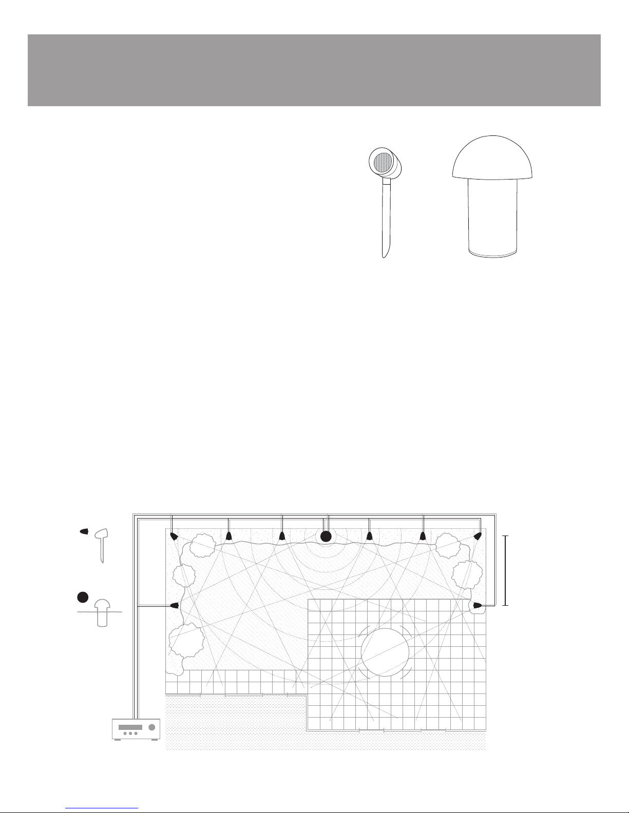
Speaker Layout Planning
The SONARRAY SR1 SYSTEM is designed to deliver a seamless,
evenly dispersed sound field in an ‘open air’ environment. An
array of multiple satellite speakers and a subwoofer should be
strategically placed to minimize ‘hot spots’ and ‘cold spots’ as
you move around the outdoor entertainment area. See Figure 1.
The satellites speakers should be placed from 6 to 8 feet (1.8 -
2.4 meters) apart for best coverage. To achieve the best balance
between the satellites and subwoofer, the subwoofer should be
placed as close to the center of the satellites as possible. If more
bass is required, placing the subwoofer near a wall or other solid
structure will greatly reinforce the low bass frequencies. In some
cases you may want to place the subwoofer closer to your primary
listening position.
The satellites in the SONARRAY SR1 SYSTEM individually present
a 30 ohm load to the amplifier. When 4 of them are connected
on each amplifier channel in parallel, the load to the amplifier
is approximately 7.5 ohms. The satellites and subwoofer both
feature internal crossovers so the subwoofers impedance is not
combined with the satellites. The overall load presented to your
amplifier by the SONARRAY SR1 SYSTEM will be around 7.5
ohms nominal.
PLEASE NOTE: The SONARRAY SR1 SYSTEM is not capable
of expansion. For coverage of a larger area, add additional
systems.
S4SAT
Satellite Speaker
S8SUB
In-Ground Subwoofer
S8SUB
S4SAT
RECEIVER
LEFT RIGHT
SONARRAY SR1 SYSTEM INSTRUCTION MANUAL
Figure 1
6-8 feet
( 1.8 to 2.4
meters )
2
WIRE GAUGE CHART
WIRE GAUGE
18 Gauge
16 Gauge
14 Gauge
12 Gauge
10 Gauge
DISTANCE
Up to 100 feet (30 meters)
Up to 150 feet (45 meters)
Up to 250 feet (80 meters)
Up to 400 feet (122 meters)
Up to 650 feet (198 meters)
Types of wire
Color-coded, 14/4 direct-burial speaker wire is recommended.
NOTE: Please refer to the wiring chart below to determine
which size wire to use over a given distance.
BEST PRACTICE: ‘14/4’ refers to 14 gauge, 4-conductor
wire. It is important to use only ‘direct burial’ wire to
maintain long-term signal integrity and prevent corrosion
from occurring to the wire. Using individual conductors with
different colors makes it easy to identify and access both
amplifier channels. Low voltage lighting wire can also be
used but is only sold as a 2 conductor wire. If using a 2
conductor wire, then run two pairs of wires; one for each
amplifier channel (Right/Left).
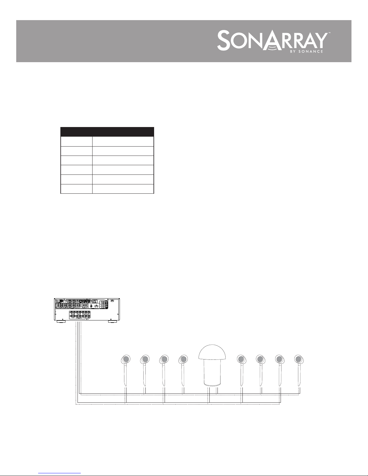
Left Right Right Left Left Right Right Left
Left and Right
S4SATs & S8SUB
A/V Receiver or Amplifier
SONARRAY SR1 SYSTEM Wiring Diagram 8 ohm
Configuration: 8 SATs to 1 SUB (all 8 SATs must be used) Non-expandable
Figure 2
Note: The subwoofer can
be connected at any point
in the daisy chain.
Speaker Installation
1. Place the 8 satellites and 1 subwoofer in their approximate
final locations.
2. Dig a 4” to 5” trench to run the speaker wires in.
3. Starting at the amp location or wire connection point, run the
speaker wire through the trench to the first speaker location.
Connecting the Speakers
The SONARRAY SR1 SYSTEM allows the satellite speakers to
be wired together in a parallel-daisy chain configuration. In a
typical system with one zone of audio, simply run a 4 conductor
wire from the amplifier or connection point to the closest speaker.
Once you have designated the first speaker as either left or right,
continue alternating the wires between the left and right channels
creating a daisy chain of stereo satellites. See figure 2.
3
 Loading...