

Sonance CINEMA SERIES, SONANCE CINEMASERIES, Cinema LCR1S, Cinema LCR.5S, Cinema SUR1S Instruction Manual
Introduction
Thank you for purchasing a Sonance Cinema®Series Ceiling
speaker. When properly installed, these speakers will deliver
film soundtracks and music with outstanding clarity and realism,
even in large home theater rooms. This manual covers the
Sonance Cinema Ceiling LCR1S, LCR.5S, and SUR1S models.
Box Contents
Each Sonance Cinema Ceiling speaker box contains the following:
(1) Cinema Ceiling LCR or SUR speaker
(1) Paintable grille
(1) Hex bit (for use with a cordless drill/screwdriver)
(1) Mounting cutout template
Speaker Placement
Cinema Ceiling LCR1S and LCR.5S Speakers
The left, center, and right speakers should be located 8 – 18 feet
from the listeners. The height and size of the television will
largely determine this distance. As a rule of thumb, higher
ceilings will require that the speakers be placed farther away
from the listening positon. For example, if the television is placed
at eye-level and the speakers are installed in an 8-foot ceiling
less than 6 feet in front of the listening position, the picture and
sound could seem very disconnected.
The speakers should be located 3 – 4 feet from the wall the
television is on. All three speakers should be the same
distance from the wall. The left and right speakers should be
separated approximately 8 – 12 feet apart and be placed 2 – 3
feet from the side walls. The center speaker should be placed as
close to the midpoint between the left and right speakers as
possible. IMPORTANT
: ALL THREE FRONT SPEAKERS MUST BE ORIENTED
WITH THEIR MIDRANGE
/TWEETER UNITS FACING THE LISTENING POSITION.
Use Figure 1 as a guide.
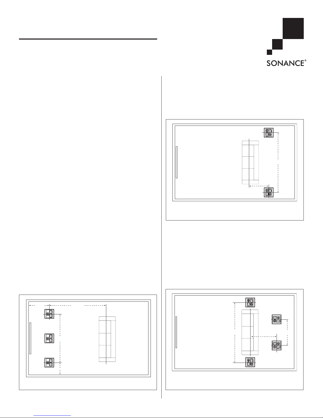
Cinema Ceiling SUR1S Speakers
5.1-Channel System
(see Figure 2)
• Place the left and right surround speakers on the ceiling 2 – 4
feet behind the listening position. The speakers should be
8 – 12 feet apart, and oriented so their driver panels face the
room’s front and rear walls.
7.1-Channel System (see Figure 3)
•• LLeeff tt aanndd RRii gghh tt SS uu rr rr oouunndd SSpp ee aakk eerr ss::
Place the left and right
surround speakers on the ceiling directly to the sides of the
listening position, 8 – 12 feet apart, oriented with their driver
panels facing the room’s front and rear walls.
•• SS uu rrrr oo uu nn dd BBaacckk SSpp ee aakk eerr ss::
Place the surround back speakers
on the ceiling 4 – 8 feet behind the listening position.
The surround back speakers should be 4 – 8 feet apart, and
oriented with their driver panels facing the room’s side walls.
8' – 12'
2' – 3'
3' – 4'
8' – 18'
TV
FIGURE 1: CINEMA CEILING LCR1/LCR.5 SPEAKER PLACEMENT
INSTRUCTION MANUAL
SONANCE CINEMA®SERIES
CEILING SPEAKERS
1
8' – 12'
2' – 4'
TV
FIGURE 2: CINEMA CEILING SUR1S SPEAKER PLACEMENT
IN A
5.1-C
HANNEL SYSTEM
Right
Surround
Left
Surround
Left
Surround
Back
Right
Surround
Back
4' – 8'
8' – 12'
4' – 8'
TV
FIGURE 3: CINEMA CEILING SUR1S SPEAKER PLACEMENT
IN A
7.1-CHANNEL SYSTEM
2
SONANCE CINEMA®CEILING SPEAKERS
Before Installation
NOTE: ALL CINEMA CEILING SERIES SPEAKER MODELS HAVE THE
SAME INSTALLATION REQUIREMENTS.
1. Determine the location for the speaker (see Speaker
Placement, on page 1).
2. Perform an obstruction survey to be certain that there are no
studs, conduit, pipes, heating ducts, or air returns in the ceiling
cavity that will interfere with the speaker.
3. The cutout for Cinema Ceiling speakers is
12
3
/
8" x 12
3
/
8”
(314mm x 314mm).
II MM PP OO RR TT AA NNTT
:: TT hh ee cceeii llii nn gg
MMUUSS TT
hh aavv ee
aa mmii nn ii mm uu mm ooff 1166 ”” oonn --cceenntt eerr ssttuudd cc oo nn ssttrr uu cc tt ii oonn..
There
must be at least 7
9
/
16” (192mm) depth within the
ceiling cavity for the speaker.
4. In ceilings with standard 2 x 10, 2 x 12, TJI 110, or TJI 210
joist construction, the RotoLock clamps will deploy without
requiring modification (see Figure 4). The maximum ceiling
material thickness in this application is 1¼” (32mm).
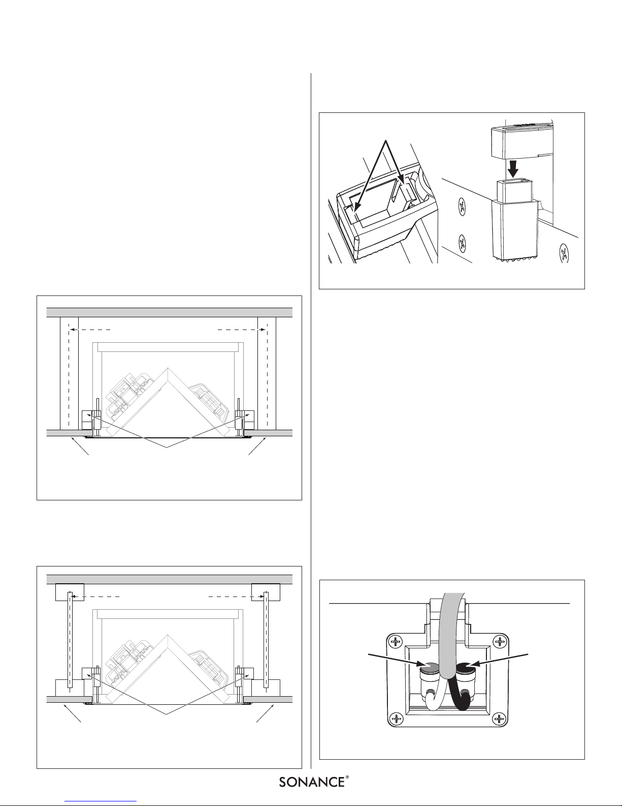
5. In ceilings with TJI 230, 360 and 560 joist construction you will
need to remove the caps of the RotoLock clamps to allow the
deployed clamps to clear the joists (see Figure 5). The maximum
ceiling material thickness in this application is
5
/
8” (16mm).
To remove the clamp caps, use a small screwdriver to gently
release the two locking levers (Figure 6, left). Then remove
the caps from the clamps (Figure 6, right).
6. Position the included mounting cutout template where the
speaker is to be located and pencil an outline on the ceiling.
7. Cut the mounting hole using a keyhole or drywall saw,
and run the speaker wire from the mounting hole to the
amplifier location.
IMPORTANT: CONSULT LOCAL BUILDING CODES BEFORE RUNNING
SPEAKER WIRES THROUGH CEILINGS AND WALLS
.
Installation
Sonance Cinema Ceiling Series speakers feature an integral
RotoLock
®
mounting system for quick mounting directly into
existing ceilings.
1. Strip ¼” – ½” of insulation from each speaker lead. Twist the
strands or tin the exposed wire with solder to ensure that there
are no stray strands. (Stray strands that touch each other can
cause a short-circuit that can damage the amplifier.)
2. The speaker’s connector posts are spring-loaded.
Push the top of each connector post down to open the
connector and insert the exposed wires into the holes in the
posts. The speaker’s positive post is labeled with a red dot;
the negative post is labeled with a black dot. Double-check
that you connected amplifier “+” to speaker “+” and
amplifier “–” to speaker “–”. (See Figure 7.)
FIGURE 7: CONNECTING THE SPEAKER WIRE
Red Dot
(+)
Black Dot
( – )
Standard & TJI 110/210 Joists
16” On-Center
RotoLock Clamps
(Deployed)
Ceiling
Drywall
Ceiling
Drywall
FIGURE 4: INSTALLATION IN STANDARD JOIST, TJI 110 AND TJI210
J
OIST CONSTRUCTION
TJI 230/360/560 Joists
16” On-Center
RotoLock Clamps
(Without Caps, Deployed)
Ceiling
Drywall
Ceiling
Drywall
FIGURE 5: INSTALLATION IN TJI 230, TJI360 AND TJI560
J
OIST CONSTRUCTION
Locking Levers
Remove
Cap
FIGURE 6: REMOVING THE CAPS FROM THE ROTOLOCK CLAMPS
 Loading...