


SONAMP
®
ASAP1D
S
TEREO POWER AMPLIFIER
INSTRUCTION MANUAL

S
ONAMP
®
ASAP1D S
TEREOPOWERAMPLIFIER
2
Important Safety Instructions
Basic safety precautions should always be followed when
using your ASAP1D amplifier, to reduce risk of fire,
electric shock, and injury to persons:
1. Read and understand all instructions.
2. Retain these instructions for future reference.
3. Follow all warnings and instructions in this manual and
marked on the product.
4. Any service or repair required must be performed by
qualified factory-authorized personnel.
5. Do not use the amplifier in a high-humidity environment or
near water — for example in a wet basement, or near a
wet bar or swimming pool.
6. Always provide adequate ventilation for the amplifier.
Allow a minimum of two (2) inches (51mm) on all sides
of the amplifier. Do not block the cooling vents on the
amplifier case.
7. The amplifier should be situated away from heat sources
such as heat registers, radiators, stoves, or other
appliances that produce heat.
8. The amplifier should only be connected to a power supply
of the type marked on its back panel. The power supply
cord should be routed to avoid damage from contact with
sharp objects or being stepped on.
9. Unplug the amplifier during thunderstorms or when it will
be unused for extended periods of time.
10. Exercise care to avoid spilling liquids on or in the amplifier.
11. Do not place the amplifier on an
unstable table, stand, or cart.
Improper placement of the
amplifier may cause it to fall on
an adult or child causing serious
injury, as well as damage to the
amplifier.
12. Do not expose the amplifier to
dripping or splashing. Do not place objects filled with
liquids, such as vases, on the amplifier.
13. Cleaning: To clean the amplifier, wipe it with a soft cloth.
Do not use solvents, as they may damage the amplifier.
14. Non-Use Periods: Unplug the amplifier’s power cord from
the electrical outlet when the amplifier will be unused for
a long period of time.
15. Damage Requiring Service: The amplifier should be
serviced by qualified service personnel when:
A. The power cord or plug has been damaged
B. Objects have fallen, or liquids have been spilled into
the amplifier
C. The amplifier has been exposed to rain.
D. The amplifier does not appear to be operating properly
or exhibits a marked change in performance.
E. The amplifier has been dropped or appears to have
been damaged.
16. Servicing: The user should not attempt to service the
amplifier beyond that described in these instructions. All
other servicing should be referred to qualified service
personnel.
17. Storms: To prevent damage to components, unplug all
electronic equipment during thunderstorms.
3
S
ONAMP
®
ASAP1D S
TEREOPOWERAMPLIFIER
Introduction
Thank you for purchasing the Sonance ASAP1D amplifier.
When properly installed, this amplifier will give you many
years of entertainment pleasure. To get the most out of your
new amplifier, please read this manual thoroughly before you
begin installation.
To achieve the best performance, Sonance recommends that
this amplifier be installed by a Sonance Authorized
Dealer/Installer.
Design
The ASAP1D will automatically switch a pair of speakers
between a whole-home audio system that normally plays in
the area (the
House
source), and a nearby source, usually a
TV set or iPort
®
(the
Local
source). The ASAP1D can be set up
so that it will automatically switch from the House source to
the Local source when it senses either an audio signal or a
video signal from the Local source.
A typical application would be to use the ASAP1D to
power and automatically switch a pair of speakers in a
bedroom from playing background music sent by a wholehome audio system to playing the sound of the bedroom TV
whenever the TV is switched ON.
The ASAP1D utilizes a highly-efficient digital amplifier that
provides 25 watts RMS per channel in stereo. The ASAP1D
produces high power in a small package, with very little heat
generation. This expands installation options, improves longterm reliability and provides significant energy savings over
conventional amplifier designs.
Box Contents
Your ASAP1D amplifier box should contain the following:
(1) ASAP1D Power amplifier
(1) Wall-hanger bracket
(4) Stick-on rubber feet
Unpacking
Save the shipping carton and polystyrene inserts so you can
safely transport your amplifier in the future. Before you install
the amplifier, locate the serial number on its rear panel and
note it here for future reference:
S/N:
Placement
The Sonamp ASAP1D is designed to operate automatically
and is housed in a compact chassis that can be conveniently
mounted out of sight. The amplifier can be placed
horizontally on the supplied rubber feet, or it can be hung on
a wall using the included wall-hanger bracket.
Stand-Alone Placement
IMPORTANT: TO AVOID DAMAGE, WHEN MOUNTED
HORIZONTALLY THE AMPLIFIER MUST ALWAYS REST ON ITS
FOUR FEET TO ALLOW SUFFICIENT CLEARANCE FOR PROPER
VENTILATION.
Apply the four supplied stick-on feet to the amplifier’s bottom
panel and place the ASAP1D on a level surface, in an upright
position, out of direct sunlight and away from windows
through which rain may enter.
Situate the amplifier away from heat sources such as hot air
ducts or radiators. Be sure that the amplifier is adequately
ventilated by convection cooling or suitable cabinet fans.
When using the ASAP1D with a TV set, it may be
convenient to hide the amplifier inside of the TV cabinet or
bookshelf (but not on the TV itself).
IMPORTANT: THE ASAP1D REQUIRES 2” (51MM) OF
CLEARANCE ON THE TOP AND ALL SIDES.
• Never place any object on or against the amplifier
• Never operate the amplifier on a carpeted surface, as this
will compromise ventilation.
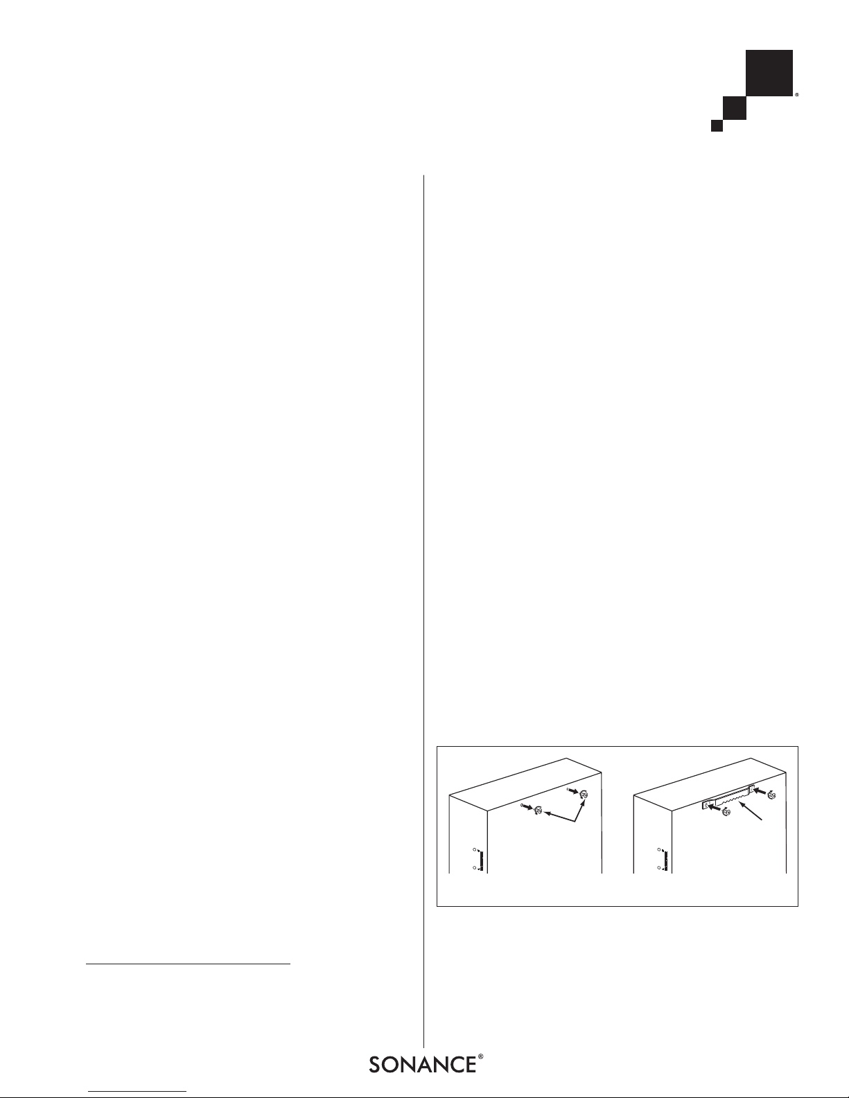
On-Wall Placement
1. Remove the two screws on the underside of the amplifier
that are shown in
Figure 1A
.
2. Use the two screws to attach the wall hanger to the
amplifier, as shown in
Figure 1B
.
3. Mount the amplifier on the wall vertically.
NOTE: BE SURE THAT THE HARDWARE ON THE WALL CAN
SUPPORT THE AMPLIFIER
’S WEIGHT (7 LB. — 3.2KG).
AB
Remove
Screws
Attach
Hanger
FIGURE 1: ATTACHING THE WALL H ANGER TO THE ASAP1
S
ONAMP
®
ASAP1D S
TEREOPOWERAMPLIFIER
4
Powering the Amplifier
Power Cord
The 120V version of the ASAP1D has a permanent power
cord; the 230V version has an IEC power cord connection.
(A power cord is not supplied with the 230V version.)
IMPORTANT: DO NOT PLUG THE POWER CORD INTO THE
WALL OUTLET UNTIL ALL SYSTEM CONNECTIONS HAVE BEEN
MADE AND VERIFIED.
AC Fuse Holder
To replace the AC fuse, unplug
the power cord from the wall
outlet and use a philips screwdriver to remove the fuse from
the holder (see
Figure 3
).
CAUTION: FOR CONTINUED
PROTECTION AGAINST FIRE,
REPLACE THE FUSE WITH ONLY THE SAME TYPE AND RATING.
Audio Input Connections
IMPORTANT: ALWAYS UNPLUG THE AMPLIFIER’ S POWER
CORD FROM THE WALL OUTLET BEFORE MAKING AUDIO,
CONTROL OR SPEAKER CONNECTIONS.
HOUSE Speaker Input
The component connected to the HOUSE speaker input
(see
Figure 4
) is
the amplifier’s
default input signal
that is passed
unamplified to the
speakers in the
absence of an
audio signal at
either the L
OCAL
source line or LOCAL
source speaker inputs.
FOR CONTINUED PROTECTION AGAINST FIRE HAZARD USE ONLY SAME TYPE AND RATING FUSE.
SONANCE
SAN CLEMENTE, CA
S/N
LEFT IN
AMPLIFIED
SPEAKER OUT
USE 8Ω SPEAKERS
HAZARDOUS ENERGY, MAKE PROPER SPEAKER
CONNECTIONS; SEE OWNERS MANUAL BEFORE USING
DISCONNECT SUPPLY CORD BEFORE CHANGING FUSE
ATTENTION: DEBRANCHER AVANT DE REMPLACER LE FUSIBLE
ATTENTION: VOIR LE CAHIER D' INSTRUCTION
ATTENTION: UTILISER UN FUSIBLE DE RECHANGE DE MEME TYPE
CAUTION:
120VAC/60Hz
56W MAX
56VA
AC FUSE
VOLUME CONTROL
B TO A
DELAY ADJUST
AB
TRIGGER
SENSITIVITY
LR
T2AL
250V
VIDEO
TRIGGER
SPEAKER LEVEL INPUT
A
HOUSE
B
LOCAL
L
RIGHT IN
R
L
R
CAUTION
RISK OF ELECTRIC SHOCK
DO NOT OPEN
ASAP1D
WARNING:
230V~50Hz
1250VA
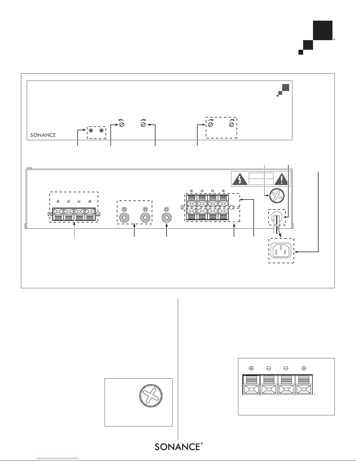
Active Input
Indicators
Speaker
Outputs
Switching
Delay Time
Adjustment
Trigger
Sensitivity
Adjustment
Volume
Controls
Local Source
Line Inputs
Video Trigger
Input/Mono
Output
House
Source
Speaker
Input
Fuse
Holder
Power Cord
(120V ver.)
IEC Power
Socket
(230V ver.)
Local
Source
Speaker
Input
FIGURE 2: ASAP1D FRONT AND REAR PANELS
AC FUSE
T2AL
250V
FIGURE 3:
F
USE HOLDER
SPEAKER LEVEL INPUT
A
HOUSE
L
R
FIGURE 4:
H
OUSE SPEAKER INPUT
 Loading...