

Page 1
SONAMP 2120T MKII HIGH-CURRENT AMPLIFIER
Congratulations on your purchase of this precision audio component and
thank you for your selection of Sonance®. Your Sonamp has been designed
with the latest technology to become the heart of the finest home theater and
music systems. Its high power output is matched by enormous current
capacity to drive multiple pairs of high-quality speakers. A robust toroidal
transformer provides reserve power. An ultra-fast discrete class AB output
stage assures flawless audio reproduction. There’s even a ground-lift switch to
combat hum in rack-mount installations. You have made an excellent choice.
The Sonamp 2120T MKII is ETL listed.
Please take a few moments now to read these instructions thoroughly so you
may fully understand the sophisticated capabilities of your new power amplifier.
IMPORTANT SAFETY INSTRUCTIONS
1. Read instructions — All the safety and operating instructions should be
read before the amplifier is operated.
2. Retain instructions — The safety and operating instructions should be
retained for future reference.
3. Heed Warnings — Adhere to all warnings and precautions listed on the
amplifier and in the operating instructions.
4. Follow instructions — Follow all operating instructions.
5. Water and Moisture — The amplifier should never be used next to water —
for example, near a bathtub, kitchen sink, laundry tub, in a wet basement,
or near a swimming pool, etc.
6. Carts and Stands — The amplifier should be used only with a cart or stand
that is recommended by the manufacturer.
• An amplifier and cart combination should be moved with care. Quick
stops, excessive force, and uneven surfaces may cause the amplifier and
cart combination to overturn.
7. Caution — To prevent electric shock, do not use the amplifier’s polarized
plug with an extension cord, receptacle or other outlets unless the blades
can be fully inserted to prevent blade exposure.
8. Ventilation —The amplifier should be situated so that its location does not
interfere with its proper ventilation. For example, the amplifier should not
be situated on a bed, sofa, rug, or similar surface that may impede the flow
of air through the ventilation openings.
9. Heat — The amplifier should be situated away from heat sources such as
radiators, heat registers, stoves, or other appliances (including other
amplifiers) that produce heat.
10. Power sources — The amplifier should be connected to a power supply
only of the type described in the operating instructions or as marked on
the amplifier.
11. Grounding or Polarization — Precautions should be taken so that the
grounding or polarization means of the amplifier are not defeated.
12. Power-Cord Protection — Power supply cords should be routed so that
they are not likely to be walked on or pinched by items placed upon or
against them,paying particular attention to cords at plugs, convenience
receptacles, and the point where they exit from the amplifier.
13. Cleaning — The amplifier should be cleaned only as recommended by the
manufacturer.
14. Non-Use Periods — The power cord of the amplifier should be unplugged
from the outlet when left unused for a long period of time.
15. Object and Liquid Entry — Care should be taken so that objects do not fall
and liquids are not spilled into the enclosure through the openings.
16. Damage Requiring Service — The amplifier should be serviced by
qualified service personnel when:
a. The power-supply cord or the plug has been damaged
b. Objects have fallen, or liquid has been spilled into the amplifier
c. The amplifier has been exposed to rain
d. The amplifier does not appear to operate normally or exhibits a marked
change in performance
e. The amplifier has been dropped, or the enclosure damaged
17. Servicing — The user should not attempt to service the amplifier beyond
that described in the operating instructions. All other servicing should be
referred to qualified service personnel.
1
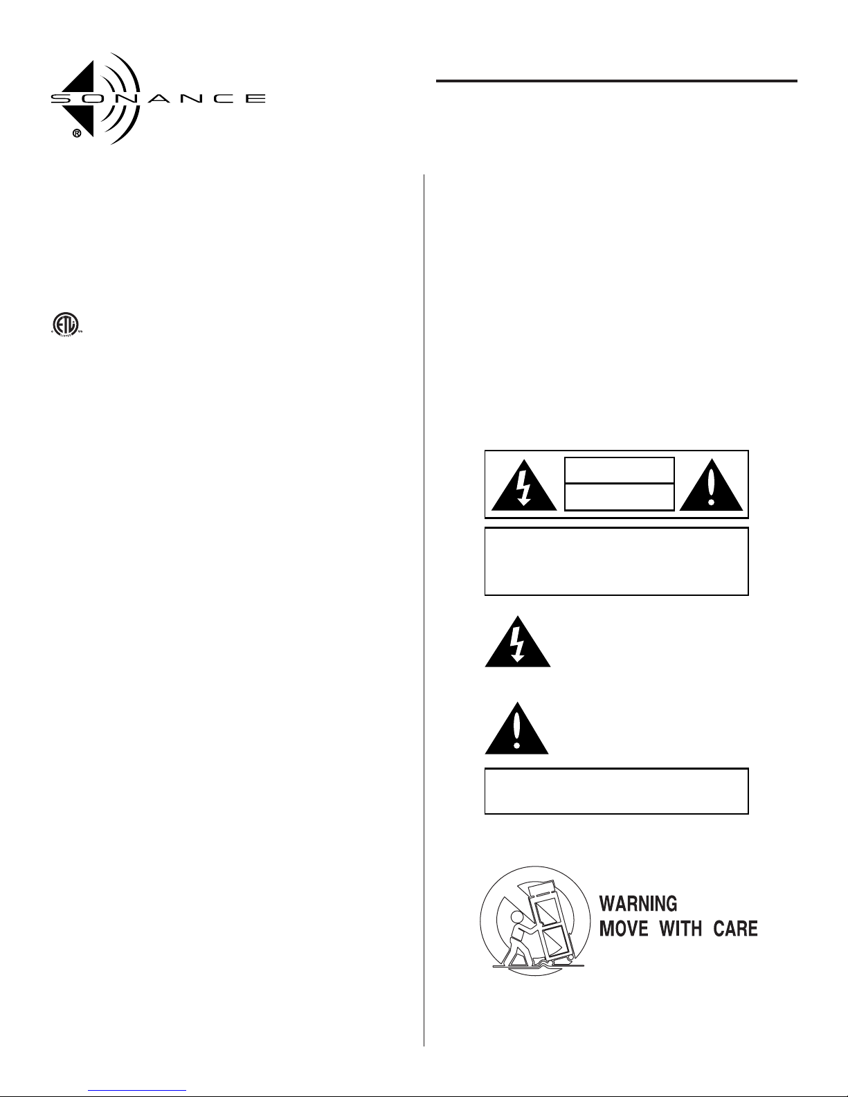
CAUTION
RISK OF ELECTRIC SHOCK
DO NOT OPEN
CAUTION: TO REDUCE THE RISK OF ELECTRIC SHOCK,
DO NOT REMOVE COVER (OR BACK)
NO USER SERVICEABLE PARTS INSIDE
REFER SERVICING TO AUTHORIZED
SERVICE PERSONNEL
The lighting flash with arrowhead symbol, within an
equilateral triangle, is intended to alert the user to the
presence of uninsulated dangerous voltage within the
product's enclosure that may be of sufficient magnitude
to constitute a risk of electric shock to persons.
The exclamation point within an equilateral triangle is
intended to alert the user to the presence of important
operating and maintenance (servicing) instructions in the
literature accompanying the appliance.
WARNING: TO PREVENT FIRE OR SHOCK HAZARD,
DO NOT EXPOSE THIS APPLIANCE TO
RAIN OR MOISTURE
INSTRUCTION MANUAL
SONAMP®2120T MKII
STEREO POWER AMPLIFIER
Page 2
UNPACKING
Save the carton and the styrofoam inserts for future safe transport, in case you
move or the amplifier ever requires shipping for repair. It is best if you place
it into an additional outer “over-carton” before shipment to minimize the
chance of theft in shipment.
Before you proceed, find the serial number which is located on the rear panel
of the unit and note it here for future reference.
S/N: __________________________________________
PLACING THE AMPLIFIER
• Keep the amplifier out of direct sunlight and away from windows that could
let in rain.
• The amplifier should be placed away from heat sources such as hot air ducts
or radiators.
• Do not place the amplifier directly on carpet that could interfere with airflow
into its bottom vent openings.
• If you place the amplifier on the floor, elevate it up off the carpet.
• If you stack your components, it is better to place the amplifier above or
alongside your other components. When driven hard, the amplifier creates
significant heat and can affect components stacked on top of it.
• If you place the amplifier inside a cabinet, allow ample ventilation and at
least 2" clearance on top and both sides.
• Very sensitive low-level sources might pick up some hum radiated from the
amplifier’s power supply.
MAKING CONNECTIONS
Before making any signal or speaker connection, make sure the amplifier is
turned OFF and unplugged.
When making connections, make sure there is no strain or tension on input
leads or speaker wires that could cause them to pull loose in the future.
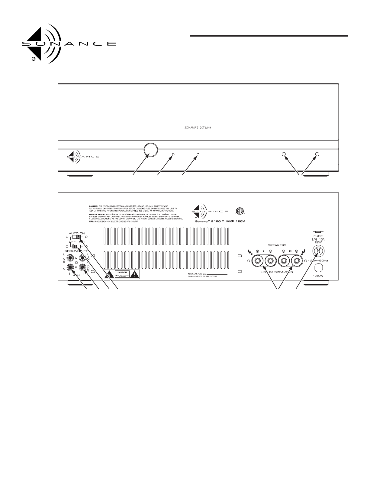
Input Connections (
Figure 1
, #5)
Connect the source component to the R and L Line Inputs.Make sure these are
consistent with R and L outputs from your preamplifier or source component.
2
INSTRUCTION MANUAL
SONAMP®2120T MKII
STEREO POWER AMPLIFIER
Rear
Front
POWER LRA.C. ONACTIVE
12 3
5 6 7 8 9 10
4
1. POWER SWITCH
2.
ACTIVE
L.E.D.
3.
AC ON
L.E.D.
4. INPUT LEVEL CONTROLS
5. LINE INPUTS
6. LINE (LOOPING) OUTPUTS
7. GROUND LIFT SWITCH
8. AUTO-ON SWITCH
9. SPEAKER CONNECTIONS
10. AC FUSE
Figure 1:
Front and
Rear Panels
Page 3

Line Outputs (
Figure 1
, #6)
The 2120T MKII provides a pair of RCA Line Out jacks which duplicate the
input signal. These can link additional power amplifiers to a single source
component without using messy Y-cord adaptors.
Speaker Connections
(
Figure 1
, #9)
The Sonamp 2120T MKII features binding post speaker connectors that can
accept bare wire and wire terminated in pins or single banana connectors.
Note: If using single banana connectors, be sure the terminals are closed
(rotated fully clockwise) before inserting the connector.
If you use bare wire, make sure you strip only enough wire (½") to fit into the
slot in the terminal. Before inserting the wire, twist all strands tightly to prevent strays that could cause a short circuit between the “+” and “–” terminals!
Insert wire in the direction of terminal rotation (clockwise) to force the wire
around the terminal post to make a secure connection.
Polarity
It is important to observe correct polarity for proper stereo reproduction.One
side of the speaker lead will have some sort of mark, either printing, a raised
ridge on the insulation or different color of conductor. This permits you to
know which wire you had connected to the “+” and which to the “–” speaker
terminals so you can repeat these connections at the power amplifier terminals.
Connecting Multiple Speakers
The Sonamp®2120T MKII is stable into low impedances, so it can drive more
than one pair of 8-ohm speakers. If you are in doubt about the impedances
of your speakers, consult your dealer or Sonance Technical Support.
To connect more than one pair of speakers to the 2120T MKII, you will need
to connect the speaker wires from each speaker in parallel. The safest and
most efficient way to do this is to use dual-banana plug connectors which are
plugged into each other, end-to-end. If you are connecting bare wires from
each pair of speakers together, we recommend you make this junction at a
point that is not immediately at the speaker terminals. This is because each
joined bundle of wires will be too thick to fit into its speaker terminals and
you will run the risk of causing a short circuit between the “+” and “–”
terminals. We recommend using a Sonance SS6 or SS4 speaker selector to
connect multiple pairs of speakers.
Use Good Speaker Wire
For best results you should never use thin gauge speaker wire – it will constrict
the sound and deteriorate bass response. We recommend use of premium
Sonance MediaLinQ® speaker cable, which also complies with UL fire rating.
You may also wish to experiment with audiophile-grade speaker cable and
interconnects, but be sure to check local codes governing wire that may be
installed within walls or ceilings. Each brand of wire will have a different
characteristic sound and some may be more compatible with the sonic
“signature”of your various components.Your Sonamp 2120T MKII is stable
with any reputable brand of wire or speaker cable.
POWERING THE AMPLIFIER
You can plug the amplifier’s AC cord into a wall socket or an AC outlet on
your preamplifier. Make sure your preamp outlet rating is equal to or greater
than the 2120T MKII’s power consumption rating (750 watts). If you do not
plan to use the amplifier’s Auto On feature, you will probably want to use a
switched AC outlet that is turned on and off by your preamp's power button.
If you choose to use the 2120T MKII’s Auto On feature, you must leave the
amplifier plugged into an unswitched AC outlet that is always “live” even
when the preamp is turned off.
If you are installing the 2120T MKII in a remote zone, you may plug it into
the closest AC wall outlet that is always “live”.
Caution: To prevent electric shock, match wide blade of plug to wide slot in
the outlet, fully insert the blades into the slots.
Attention: Pour evitar les chocs electriques, introduire la lame la plus large
de la fiche dans la borne correspondante de la prise et pousser jusqu'au fond.
Use only a heavy-duty extension cord, if required, to avoid starving the
amplifier of all current necessary for full power operation.
Ground Lift Switch
(
Figure 1
, #7)
The Sonamp 2120T MKII features a ground lift switch that can eliminate
hum caused by ground loops. This often happens when rack-mount
adapters (sold separately) are used and the chassis makes contact with the
equipment rack. Flipping the Ground Lift switch may eliminate the hum,
avoiding the need to insulate the rack with nylon washers.
OPERATING THE 2120T MKII
Power Switch
(
Figure 1
, #1)
The Sonamp 2120T MKII has an ingenious and sophisticated Auto On turn
on/off circuit. Please read these instructions carefully for proper operation.
Press the power switch once to the “in” position to turn the amplifier ON.
Press the switch again to the "out" position to turn it OFF. Leave the switch in
the “in” position when using the Auto On turn on/off feature. (The Auto On
feature will automatically switch the amplifier’s power ON when an audio signal is present at its input jacks (see below).
Auto-On Switch
(
Figure 1
, #8)
When the Auto On switch is in the ON position, any audio signal arriving at the
2120T MKII’s left input jack will automatically activate the amp for operation
within 1.5 seconds. The green Active LED on the front panel will illuminate,
indicating that the amplifier is operational.
Note: The amplifier is shipped with the Auto-On switch in the
ON
position.
The amplifier will remain ON for approximately 3 minutes after the audio
signal has ceased. This provides ample time to prevent erratic operation from
pauses between musical passages or while changing signal sources. With this
feature there is no limit to where you can place the 2120T MKII. Here are a
few installation possibilities:
• Local room system coupled with a multi-CD changer
• Surround sound front, side, or rear channels
• Multi-room, multi-source control systems
If the Auto-On turn on/off feature is not required, it can be defeated by
moving the rear panel “Auto On”switch to its OFF position. Use a small flatbladed screwdriver to move the recessed switch. Do not apply excessive force.
Now the 2120T MKII’s front-panel Power Switch will function conventionally
and the amplifier will turn ON and OFF from a switched AC outlet on your
preamp.
Level Controls
(
Figure 1
, #4)
The 2120T MKII has recessed front-panel level controls that allow adjustment
by screwdriver only. This prevents accidental tampering with levels.You can use
the Level Controls to adjust the left/right channel balance, to limit the maximum safe gain to protect the speakers or to optimize the signal-to-noise ratios
between the source components and amplifier. Many volume controls, on
source components, are overly-sensitive near their minimum positions; by
reducing the 2120T MKII’s input level control settings, you “compel” the source
component volume control to operate in its more uniform adjustment range.
In a system that incorporates in-wall speaker volume controls, the
2120T MKII’s Level Controls can be used to set a safe maximum level that
prevents volume control transformer saturation, distortion or burn-out.
3
INSTRUCTION MANUAL
SONAMP®2120T MKII
STEREO POWER AMPLIFIER
Page 4

4
If you’re using the Sonamp 2120T MKII with a THX®-certified surround
processor, set the Level Controls to their maximum clockwise rotation to take
full advantage of the processor’s calibrated volume control settings.
A.C. ON
LED
(
Figure 1
, #3)
This red LED indicates that the amplifier’s AC power cord is plugged into a
live AC outlet. If the amp’s main AC line fuse ever opens, this LED will go out.
To use the Auto-On feature, this LED must remain on at all times (i.e., with
an unswitched outlet). The Power Switch has no effect on this LED.
Active
LED (
Figure 1
, #2)
The primary function of this LED is to show amplifier operational activity. In
the Auto-On mode, this LED turns ON at the presence of an audio signal to
the input jacks. The first time AC power is applied to the 2120T MKII, the
Active LED will illuminate for about 3 minutes and then extinguish. This is a
normal reaction of the Auto-On circuitry the very first time it receives power.
Thereafter, the 2120T MKII is ready for Auto-On operation.
Whenever AC power to the Sonamp 2120T MKII has been interrupted, the
Active LED will again illuminate for about 3 minutes when power is first
restored to the amplifier.
Note: When the Auto On feature is defeated the Active LED functions as a
conventional on/off power indicator.
High-Pass Filter Settings (
Figure 2
)
The 2120T MKII high-pass filters are located on the circuit board just behind
the input/output jacks. The filter settings are determined by the positions of a
pair of shorting sleeves on jumper pins.
IMPORTANT: The high-pass filter jumpers are set at the factory in the
high-pass filter
ON
position. Sonance
HIGHLY RECOMMENDS
that these
jumpers remain in the
ON
position if the amplifier will be used in a system
that includes in-wall volume controls for the speakers. The amplifier’s
high-pass filters reduce infrasonic energy and help protect autoformerbased volume controls from saturation and overload.
To bypass the high-pass filters, set the jumpers to the OFF position:
1. Unplug the amplifier’s power cord from the AC outlet.
2. Remove the amplifier’s top cover.
3. As shown in Figure 2 (next column),remove the shorting sleeves from their
factory-set (ON) position on the Hi-Pass Filter jumper pins and replace
them in the OFF positions. Make sure you insert the shorting sleeves all the
way onto the jumper pins.
4. Replace the amplifier’s top cover
PROTECTION CIRCUITS
The 2120T MKII has several circuits designed to protect the amplifier from
damage. If any are triggered, the Active LED will flash and you may hear the
sound of the protection relay clicking to protect the amplifier. After the fault
has been corrected, the amplifier will automatically reset itself for
normal operation. But it is advised that you turn off the amp’s Power Switch
while you are trouble-shooting for shorted connections or faults with source
components.
MAINTAINING YOUR SONAMP 2120T MKII
To keep the 2120T MKII clean use only a soft cloth and never use any solvents
or abrasives. Fingerprints may be removed with a soft cloth moistened only
with a few drops of water.
SPECIFICATIONS
Both Channels Driven
Output Power, Stereo mode, RMS: 120 Watts per channel @ 8 ohms;
160 Watts per channel @ 4 ohms
IHF: Dynamic Power 163 Watts per channel @ 8 ohms;
242 Watts per channel @ 4 ohms
Dynamic Headroom: +1.33dB @ 8 ohms;
+1.79dB @ 4 ohms
Total Harmonic Distortion: 0.05% (20Hz – 20kHz @ 8 ohms, 120 WRMS);
0.10% (20Hz – 20kHz @ 4 ohms, 160 WRMS)
0.01% (1kHz @ 8 ohms, 120 WRMS);
0.02% (1kHz @ 4 ohms, 160 WRMS)
I.M. Distortion (SMPTE 4:1) @ 8 ohms: 0.02% @ 1 Watt;
0.02% @ 60 Watts
Frequency Response: 20Hz – 20kHz, ±0.25dB (Hi-Pass Filter OFF)
Hi-Pass Filter Characteristic: -1dB @ 57Hz; -3dB @ 28Hz
Signal to Noise Ratio: -100dB below rated output (A-weighted)
Input Sensitivity: 1.1 Volt for 120 watts RMS @ 8 ohms;
1.0 Volt for 100 watts RMS @ 8 ohms
Input Impedance: 47k ohms
Power Consumption 750 Watts maximum (full power @ 4 ohms);
10 Watts idle (no signal)
Dimensions: 16¾" x 5
3
/8" x 125/8" (425mm x 137mm x 321mm)
Shipping Weight: 26 lb (11.8 kg)
INSTRUCTION MANUAL
SONAMP®2120T MKII
STEREO POWER AMPLIFIER
Figure 2: Hi-Pass
Filter Jumpers
Page 5

TECHNICAL ASSISTANCE AND SERVICE
If you any have questions about the operation or installation of this
product, please call our Technical Assistance Department on any business day at (800) 582-0772 or (949) 492-7777; from 7 a.m. to 5 p.m.,
Pacific Time.
If your product should need repair or service, contact your Sonance
Authorized Dealer for help, or use the following procedure:
1. Prior to calling Sonance, note the product’s model number, serial num-
ber, purchase date, and the name and address of the dealer where you
purchased the product.
2. Contact our Technical Assistance Department at the above
number(s) and describe the problem the unit is experiencing. If they
determine that the product requires service, they will transfer you to
our Customer Service Department, who will issue you a Return
Authorization (RA) Number.
IMPORTANT: YOU MUST HAVE PRIOR AUTHORIZATION TO
RETURN YOUR PRODUCT TO SONANCE!
3. If you’re directed to return the unit to Sonance for repair, pack the unit
in its original shipping carton. If needed, you can obtain replacement
packaging from us for a small charge. Note: it is best if you place the
box into an additional outer “overcarton” before shipment to minimize
a chance of theft in shipment. Please include a copy of the original bill
of sale inside the package.
4. Contact a package delivery service such as United Parcel Service or
Federal Express to arrange prepaid (not collect) shipping. Do not use
the U.S. Postal Service.
IMPORTANT: FREIGHT COLLECT SHIPMENTS WILL BE REFUSED.
5. Write the RA Number on the outside of the shipping carton.
6. Ship the packaged unit to:
Quality Assurance Department
Sonance
212 Avenida Fabricante
San Clemente, CA 92672-7531
LIMITED WARRANTY COVERAGE (U.S. ONLY)
Sonance warrants to the original retail purchaser only that this
Sonance product will be free from defects in materials and workmanship for a period of five (5) years, provided the product was purchased
from a Sonance Authorized Dealer.
Defective products must be shipped, together with proof of
purchase, prepaid insured to the Authorized Sonance Dealer
from whom they were purchased, or to the Sonance factory at the address
listed on this instruction manual. Freight collect shipments will
be refused. It is preferable to ship this product in the original shipping
container to lessen the chance of transit damage. In any case, the risk or
loss or damage in transit is to be borne by the purchaser. If, upon
examination at the factory or Authorized Sonance Dealer, it is
determined that the unit was defective in materials or workmanship at
any time during this warranty period, Sonance or the Authorized
Sonance Dealer will, at its option, repair or replace this product at no
additional charge, except as set forth below. If this model is no longer
available and can not be repaired effectively, Sonance, at is sole option,
may replace the unit with a current model of equal or grater value. In
some cases where a new model is substituted, a modification to the
mounting surface may be required. If mounting surface modification is
required, Sonance assumes no responsibility or liability for such modification. All replaced parts and product become the property of Sonance.
Products replaced or repaired under this warranty will be returned to the
original retail purchaser, within a reasonable time, freight prepaid.
This Warranty does not include service or parts to repair damage caused
by accident, disaster, misuse, abuse, negligence, inadequate packing or
shipping procedures, commercial use, voltage inputs in excess of the
rated maximum of the unit, or service, repair or modification of the
product which has not been authorized or approved by Sonance. This
Warranty also excludes normal cosmetic deterioration caused by
environmental conditions. This Warranty will be void if the Serial
Number on the product has been removed, tampered-with or defaced.
This Warranty is in lieu of all other expressed warranties. If the product
is defective in materials or workmanship as warranted above, the
purchaser’s sole remedy shall be repair or replacement as provided above.
In no event will Sonance be liable for any incidental or consequential
damages arising out of the use or inability to use the product, even
if Sonance or a Authorized Sonance Dealer has been advised of the
possibility of such damages, or for any claim by any other party.
Some states do not allow the exclusion or limitation of consequential
damages, so the above limitation and exclusion may not apply. All implied
warranties on the product are limited to the duration of this expressed
Warranty. Some states do not allow limitation on the length of an implied
warranty. If the original retail purchaser resides in such a state, this
limitation does not apply.
EXCLUSIONS AND LIMITATIONS
The warranty set forth above is in lieu of all other warranties, express or
implied, of merchantability, fitness for a particular purpose, or otherwise.
The warranty is limited to Sonance products registered herein and
specifically excludes any damage to loudspeakers and other allied or
associated equipment which may result for any reason from use with this
product. Sonance shall, in no event, be liable for incidental or consequential
damages arising from any breach of this warranty or otherwise. This
warranty gives you specific legal rights, and you may have other rights
which vary from state to state.
5
INSTRUCTION MANUAL
SONAMP®2120T MKII
STEREO POWER AMPLIFIER
Page 6

33-0434 12/05
212 Avenida Fabricante • San Clemente, CA 92672-7531, USA
(800) 582-7777 or (949) 492-7777 • FAX: (949) 361-5151 • Technical Support: (800) 582-0772
www.sonance.com
©2005 Sonance. All rights reserved.
Sonance and Sonamp are registered trademarks of Dana Innovations.
Due to continuous product improvement, all specifications are subject to change without notice.
For the latest Sonance product specification information visit our website.
 Loading...