

Introduction
Thank you for purchasing Sonance Surface-Mount Speakers.
When properly installed your new speakers will give you years
of entertainment pleasure. This manual covers the SM55 and
SM55 SST (Single-Stereo Technology
®
) speakers.
Box Contents
Item Quantity Quantity
(SM55) (SM55 SST)
Surface Mount Speaker 2 1
Paintable Grille 2 1
Speaker Terminal Screws 4 4
Speaker Placement
Distributed Audio (SM55 and SM55 SST)
The SM55 and SM55 SST’s low installation profile makes them
ideal for use in distributed audio systems. They provide coverage
of a very wide listener area, allowing them to be mounted in a
wide variety of installation locations.
Because a single SM55 SST speaker reproduces both stereo
channels from a single location, it will deliver outstanding
performance from a wide variety of mounting locations where a
pair of stereo speakers would be impractical, including hallways,
bathrooms and closets.
The table and illustration below show how far apart the speakers
can be placed at various ceiling heights while still providing good
coverage for all listeners.
Ceiling Height Spacing (Standing) Spacing (Seated)
9-Foot Ceiling 5’7” 9’5”
10-Foot Ceiling 9’7” 13’5”
12-Foot Ceiling 13’7” 17’5”
14-Foot Ceiling 17.7’ 21.5’
Surround Channel (SM55)
The SM55’s low-profile design and wide area coverage also
make it an excellent choice for surround channel applications in
home theater systems.
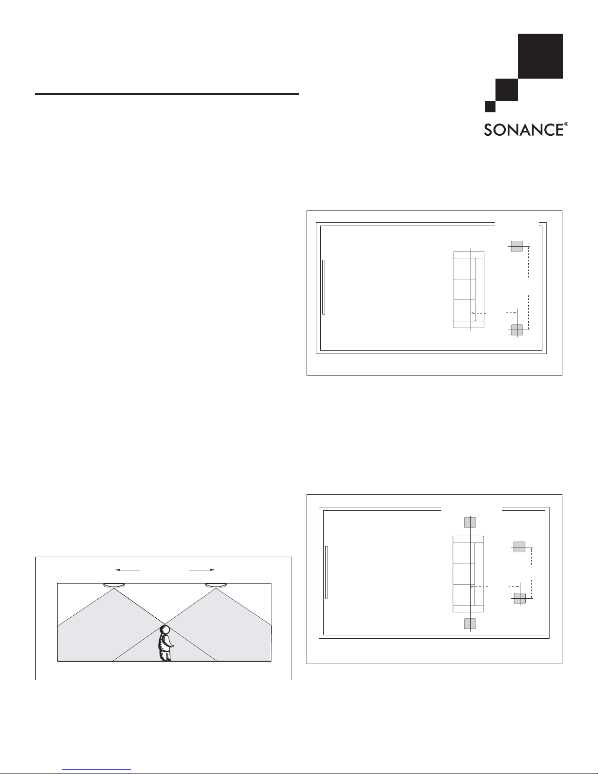
5.1-Channel System
(see Figure 2)
• Locate the left and right surround speakers on the ceiling
between 2 feet and 6 feet behind the listening position. The
speakers should be between 6 feet and 10 feet apart.
7.1-Channel System (see Figure 3)
•
LLeefftt && RRiigghhtt SS uu rr rroouunndd SSppeeaa kkeerr ss ::
Place the left and right surround speakers directly to the sides of the listening position,
between 6 feet and 10 feet apart.
•
SSuu rr rroouunndd BBaacc kk SSppeeaakk ee rrss::
Place the surround back speakers
between 2 feet and 6 feet behind the listening position. The
surround back speakers should be closer together than the left
and right surround speakers — between 3 feet and 6 feet
apart.
Before Installation
1. Determine the location for the speaker (see Speaker
Placement).
2. The SM55 and SM55 SST Mounting Plates (available separately) are designed to install onto a J-box (single or double)
that has already been mounted in the ceiling.
INSTRUCTION MANUAL
SM55 AND SM55 SST
SURFACE-MOUNT SPEAKERS
TV
3' – 6'
Apart
2' – 6'
Surround
Back
Speakers
Left & Right
Surround Speakers
FIGURE 3: 7.1-CHANNEL SURROUND CHANNEL SPEAKER PLACEMENT
TV
6' – 10'
Apart
2' – 6'
Left & Right
Surround
Speakers
FIGURE 2: 5.1-CHANNEL SURROUND CHANNEL SPEAKER PLACEMENT
1
C
OVERAGE
A
REA
C
OVERAGE
A
REA
S
PEAKER
S
PACING
FIGURE 1: DISTRIBUTED AUDIO COVERAGE AREA
2
SONANCE SM55 & SM55 SST SURFACE-MOUNT SPEAKERS
• The Mounting Plate allows the speaker to be installed after
the ceiling has been finished. The Mounting Plate also
allows the speaker to be rotated after installation to align it
with design elements in room.
3. If there is no J-box in the ceiling, the speaker can be mounted
directly on the ceiling surface without using the Mounting Plate.
IMPORTANT: Anchors and attachments appropriate
for the ceiling construction must be used if the
Mounting Plate is not used. It is the responsibility
of the installer to select anchor and attachment
devices appropriate for the ceiling construction.
NOTE
: IF THE SPEAKER IS INSTALLED WITHOUT THE MOUNTING
PLATE IT CANNOT BE ROTATED AFTER INSTALLATION
.
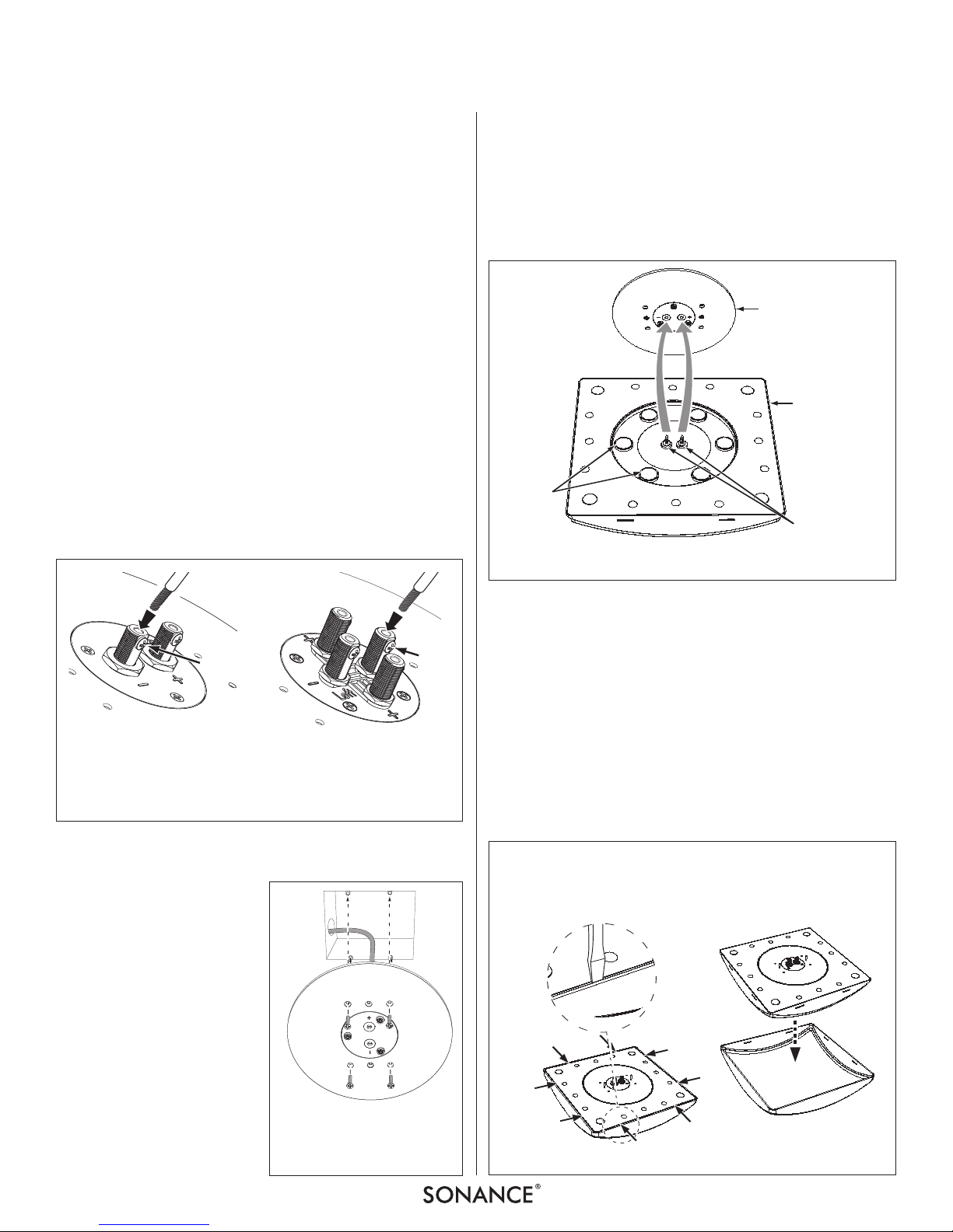
Installation Using a J-Box
1. Run speaker wires through the ceiling or conduit, from the
amplifier into the J-Box. Mark the wire’s “+” and “–” leads.
• Consult local building codes before running speaker wires
through ceilings.
2. Bring the speaker wires through the J-Box and attach them to
the binding posts on the back of the Mounting Plate. (The
SM55 plate has one set of posts; the SM55 SST plate has two
sets, see Figure 4.) The binding posts will accept single
banana plugs or bare wire.
• Loosen the set screw on the binding post, insert the plug or
wire, then tighten the set screw to secure the wire.
IMPORTANT: When
using bare wire, be
sure that no stray “+”
and “–” strands touch
each other. (Stray
strands that touch
each other can cause
a short-circuit that can
damage the amplifier.)
3. Use the 1½” x 6-32 flat head
screws included with the
Mounting Plate to attach it to
the J-Box. (See Figure 5.)
• Use two screws for a sin-
gle-gang J-Box; use four
screws for a double-gang
J-Box.
4. The Mounting Plate is fitted with a paint plug that protects the
speaker terminals if the ceiling is painted after the Plate is
installed. Remove the paint plug before installing the speaker.
5. To install the speaker, place the speaker against the Mounting
Plate so that the male terminal connectors on the speaker fit
into the female connectors on the Mounting Plate. The
neodymium magnets on the speaker will secure the speaker to
the Mounting Plate. (See Figure 6.)
Be sure to align the “+” and “–” connectors on the speaker with
the corresponding connectors on the Mounting Plate.
• After the speaker is installed you can rotate it to align it with
design elements in the room. See Speaker Adjustments:
Rotating the Speaker, on page 3.
Installation Without a J-Box
1. Remove the grilles from the speakers.
• The grilles are held on the speakers by 2 small tabs on each
side of the grille frame. Use a flat-blade screwdriver to
gently pry each side of the grille frame away from the
speaker to release the tabs, and slide the grille off the
speaker (see Figure 7).
FIGURE 4: WIRING THE MOUNTING PLATE
SM55 (LEFT); SM55 SST (RIGHT)
A) Loosen Set Screw
B) Insert Wire
C) Tighten Set Screw
A, C
B
A, C
B
FIGURE 5: ATTACHING THE
M
OUNTING PLATE TO THE J-BOX
(SM55 PLATE SHOWN)
F
IGURE 6: ATTACHING THE SPEAKER TO THE MOUNTING PLATE
Mounting Plate
(installed on ceiling)
SM55
Speaker
(back side)
Neodymium
Magnets
Terminal Connections
(2 on SM55;
4 on SM55SST)
1. Insert Screwdriver Between
Grille Frame and Speaker at
Tab Locations and Gently Pry
Grille Away From Speaker
2. Slide Grille Assembly
Off Of Speaker
FIGURE 7: REMOVING THE GRILLE
 Loading...