

INSTRUCTION MANUAL
4.0"
17.625"
4.0"
SLS HIGHOUTPUT
LS15SUB IN-GROUND SUBWOOFER
Introduction
Thank you for purchasing a SLS HIGHOUTPUT Subwoofer. When
properly installed, the subwoofer will provide you with years of
outdoor entertainment pleasure. To get the most out of your new
subwoofer, please read this manual thoroughly before you begin
installation.
Box Contents
SLS HIGHOUTPUT In-Ground Subwoofer box contains:
(1) In-ground subwoofer
(1) Dark brown canopy with ABS tube
(1) Rubber elbow
(2) Stainless steel hose clamps
(2) Silicon filled wire nuts
Subwoofer Location Selection
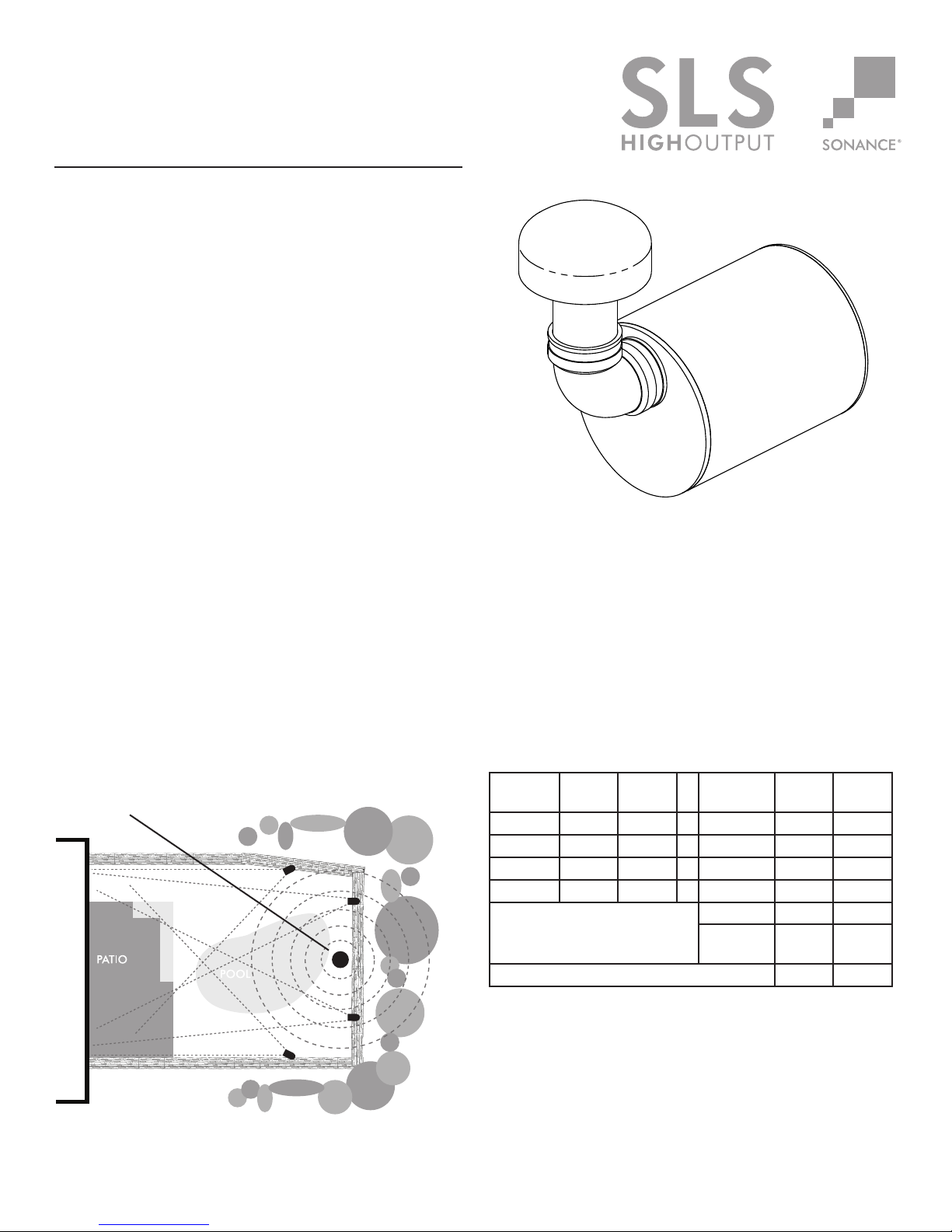
The Sonance Landscape Series is designed to deliver a seamless,
evenly dispersed sound field in an ‘open air’ environment. An array
of multiple satellite speakers and subwoofers should be strategically
placed to minimize ‘hot spots’ and ‘nulls’ as you move around the
outdoor entertainment area. See Figure 1.
As a general guideline, (1) subwoofer will cover about
2000 square feet of listening area
Figure 1 shows the SLS HIGHOUTPUT placed along the perimeter
of the entertainment area.
Select a central location for the subwoofer if using only one subwoofer
(see figure 1) if using multiple subwoofers, select locations that are
the same distance from the main listening area.
Subwoofer
LS15SUB Subwoofer
Patent Pending
Amplifier Power Planning
The maximum number of satellites and subwoofers that can be
used in a system will depend on the quantity of amplifier power
available.
Before beginning an installation use the chart below to calculate
the amplifier power your installation will require. Multiple
amplifiers may be required in large installations.
Wattage Calculator
Model Qty.
Ch.1
LS87SAT x 50
LS15SUB*
Qty.
Ch.2
x Watts Total
x 400
TOTAL WATTAGE
Sub Total
20% Head
Room
Ch.1
Total
Ch.2
Figure 1
*The LS15SUB is a dual voice coil, single-stereo subwoofer. Each
voice coil draws 200 watts, for a combined total of 400 watts.
The LS15SUB requires a 4-conductor wire to connect both it’s
left and right channel inputs.
Amplifier Selection
For systems up to 500w per channel use the CROWN CDI 1000
For systems up to 800w per channel use the CROWN CDI 2000
For systems up to 1000w per channel use the CROWN CDI 4000
1
Subwoofer Installation
70 volt audio systems allow for speakers to be daisy chained
together. In a typical system with one zone of audio you simply run a
stereo or 4 conductor wire from the amplifier to the closest speaker.
Once you have designated your first speaker as either left or right,
continue alternating the wires between the left and right channels
creating a daisy chain of stereo satellites. The subwoofer can be
wired anywhere in the chain. See figure 5.
Note: Sonance strongly recommends the use of 14
gauge or larger direct burial grade wire.
Caution: The amplifier should not be connected to AC
power until all connections are completed. High power
70 volt amplifiers present a serious shock hazard. Do
not connect speaker wires to the amplifier until all other
connections are completed.
1. Locate the subwoofer in an area that will not flood with standing
water.
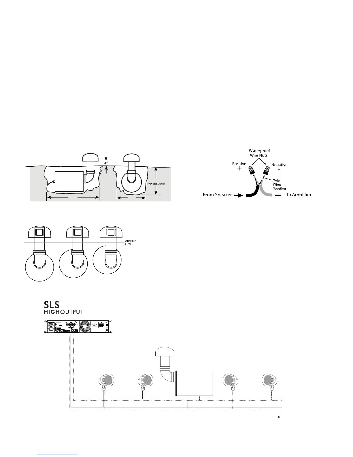
2. Dig the hole a minimum of 21”W x 49”L x 18” - 21”D.
See Figure 2
18”-21”
3. Prepare a ‘bed’ for the subwoofer that is reasonable free of
voids and large rocks.
4. Install and secure the rubber elbow onto the canopy and ABS
tube subassembly using one of the supplied hose clamps.
5. Install the rubber elbow and canopy assembly on the subwoofer
enclosure; do not tighten the second hose clamp at this point.
6. Place the subwoofer into the ground.
7. Rotate the cabinet as required so that the bottom of the canopy
will be 4” above the finished grade after backfill.
8. Once the subwoofer is in the correct location tighten the hose
clamp at the connection between the enclosure and the rubber
elbow.
9. Dig a 4” – 5” deep trench to run the speaker wires in.
10. Run the wire through the trench from your amplifier to the first
speaker location.
11. Connect the direct burial wire to each speaker wire, connections
should be made with either silicone filled wire connectors or
appropriate junction boxes. See figure 4.
49”
Figure 2
Note: (for variable depth see Figure 3 below)
Figure 3
Wiring Diagram 70V
Crown CDi Series Amplifier
LS87SATs & LS15SUB
21”
Figure 4
IMPORTANT: Be sure not to let any stray ‘+’ and ‘–’
strands touch each other. Touching strands can cause a
short-circuit that could damage your amplifier.
Note: Confirm that you have connected speaker “+” to
amplifier “+” and speaker “–” to amplifier “–”.
12. After all the speakers connections are completed, connect the
wires to your amplifier. See Figure 5 for reference.
13. Turn your amplifier on and test the system with your favorite
music. If the speakers are operating properly, refill the wire
trench and enjoy your new speakers.
Note: The subwoofer can
be connected at any point
in the daisy chain.
Figure 5
Right LeftLeft Right
Left and Right
ExpandableConfiguration: 4 SATs to 1 SUB
2
 Loading...