

Page 1
INSTALLATION MANUAL
PROFESSIONAL SERIES
SURFACE MOUNT
PS-S43T | PS-S53T | PS-S63T | PS-S83T | PS-S83WT
Page 2

TABLE OF CONTENTS
PRODUCT DESCRIPTION 2
BOX AND CONTENTS 2
PRODUCT FEATURES 3
PRODUCT PREPARATION
Amplifier Selection 4
Wire Selection
70V/100V System 4
8 ohm System 4
Speaker Placement 4
Pivoting the Speaker 4
Grille and Speaker Shell Painting 5
INSTALLATION 6
TECHNICAL SPECIFICATIONS
PS-S43T 8
PS-S53T 9
PS-S63T 10
PS-S83T 10
PS-S83WT 11
CERTIFICATIONS & SAFETY AGENCY 12
TECHNICAL ASSISTANCE & SERVICE 12
WARRANTY 13
SONANCE | PROFESSIONAL SERIES SURFACE MOUNT | INSTALLATION MANUAL 1
Page 3
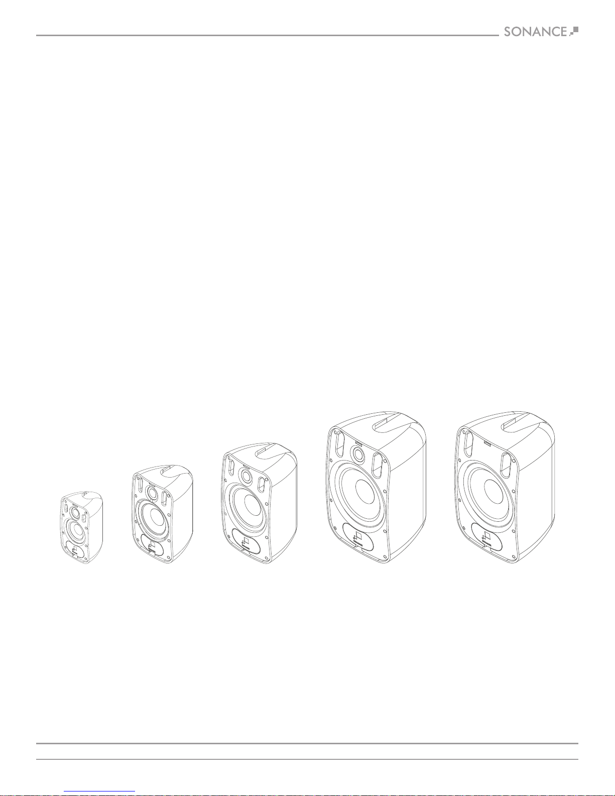
PRODUCT DESCRIPTION
BOX & CONTENTS
From Sonance, the company that created the architectural
audio category comes a range of professional loudspeakers
that set a new benchmark in sound quality and aesthetics for
commercial environments.
Introducing Sonance Professional Series
Sonance Professional Series includes a range of In-Ceiling, Pendant
and Surface Mount Speakers that deliver true full range fidelity,
extremely low distortion, wide dispersion and a smooth power
response. The range also shares consistent voicing, ensuring
seamless sonic integration when used together throughout a space.
The Surface-Mount Speakers feature Sonance’s FastMount
and front cable connection to speed up the installation process and
provide a clean appearance. Available in 4”, 5.25”, 6.5” and 8”
2-Way and 8” Woofer in either black or white.
®
bracket
2-WAY SPEAKERS
(2) PS-S43T, or PS-S53T, or PS-S63T, or PS-S83T
(2) Speaker Grille
(2) FastMount Brackets
(2) Wiring Terminal Covers
WOOFER
(1) PS-S83WT
(1) Speaker Grille
(1) FastMount Bracket
(1) Wiring Terminal Cover
PS-S43T
4” 2-Way
SONANCE | PROFESSIONAL SERIES SURFACE MOUNT | INSTALLATION MANUAL 2
PS-S53T
5.25” 2-Way
PS-S63T
6.5” 2-Way
PS-S83T
8” 2-Way
PS-S83WT
8” Woofer
Page 4
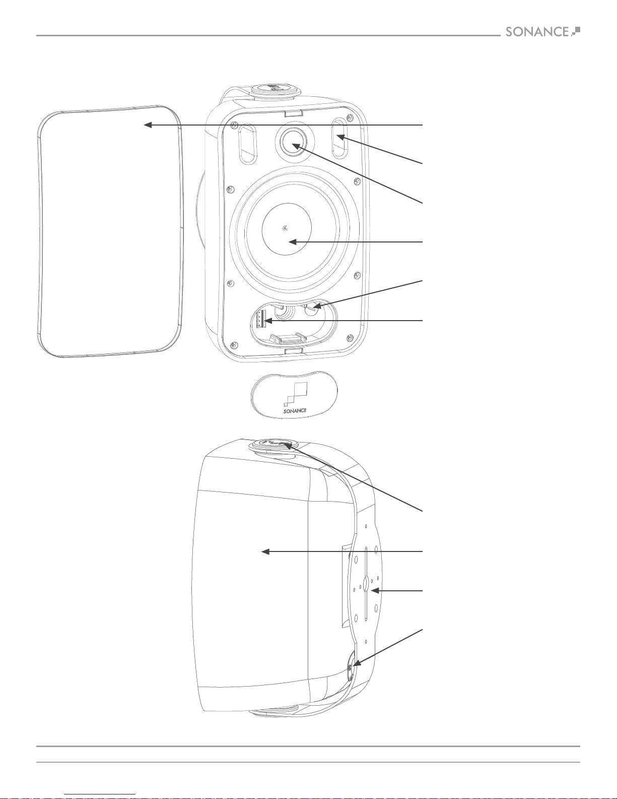
PRODUCT FEATURES
Powder Coated Aluminum Grille
Tuning Port
Chambered Tweeter (excludes PS-S83WT)
High Excursion Woofer
Transformer Tap and Bypass Selector
Euroblock Connector with Loop Through
SONANCE | PROFESSIONAL SERIES SURFACE MOUNT | INSTALLATION MANUAL 3
Rotation Lock
Paintable Shell (white only)
FastMount Bracket
Cable Pass-Through
Page 5
AMPLIFIER SELECTION
SPEAKER PLACEMENT
When choosing an amplifier the maximum number of speakers
and the output level of each speaker must be known. The sum of
the tap settings should never exceed 80% of the amplifier’s rated
output. For example, if there are 5 speakers and the taps are set
at 15 watts, the load would be 75 watts (5 x 15 watts = 75 watts).
To arrive at the needed power for this number of speakers, simply
divide the total load by .8. In this case, 75 / .8 = 93.75 watts.
Therefore, a standard 100 watt amp would safely drive this load.
To calculate the amount of usable power an amp offers, simply
multiply the rated output by .8, i.e., 100 watts x .8= 80 watts.
WIRE GAUGE – 70V/100V SYSTEM
The most common wire used on commercial 70 volt systems is
18 gauge, 2 conductor, stranded, and jacketed without a shield.
The wire starts at the amplifier location and is paralleled at each
speaker location.
Wire length using 18 gauge is appropriate up to 700 feet with a
100 watt load. If you double the load (sum of your tap settings),
you will reduce the footage by half, to 350 feet. Conversely, if you
halve the load, you may double the acceptable wire length, i.e.,
a 50 watt load is safe over 1400 feet of 18 gauge. Stepping up to
16 gauge wire extends the allowable run length by approximately
35%. For example, a 100 watt load can go 700 feet on 18 gauge;
the same load may be placed on 1100 feet of 16 gauge.
WIRE GAUGE – 8 OHM SYSTEM
When using Sonance Professional Series loudspeakers in an 8
ohm system the total wire resistance should be less than 10%
of the speaker impedance. The speakers are nominally 8 ohms
impedance, so your total wire resistance should be no more than
0.8 ohms.
In simple terms, the extra resistance from the wire will have a very
negative affect on the sound quality of the speaker. The sound can
be less dynamic, definition of bass frequencies can be reduced,
and in extreme cases, the high frequencies can be attenuated.
Amplifier power is also wasted in the wire, reducing the maximum
output level of the system.
Please refer to the following chart (see figure 1) when deciding on
the appropriate wire gauge for your installation.
Wire Resistance in Ohms vs. Length of Cable Run
Distance in Feet
50’ 100’ 150’ 200’ 250’ 300’
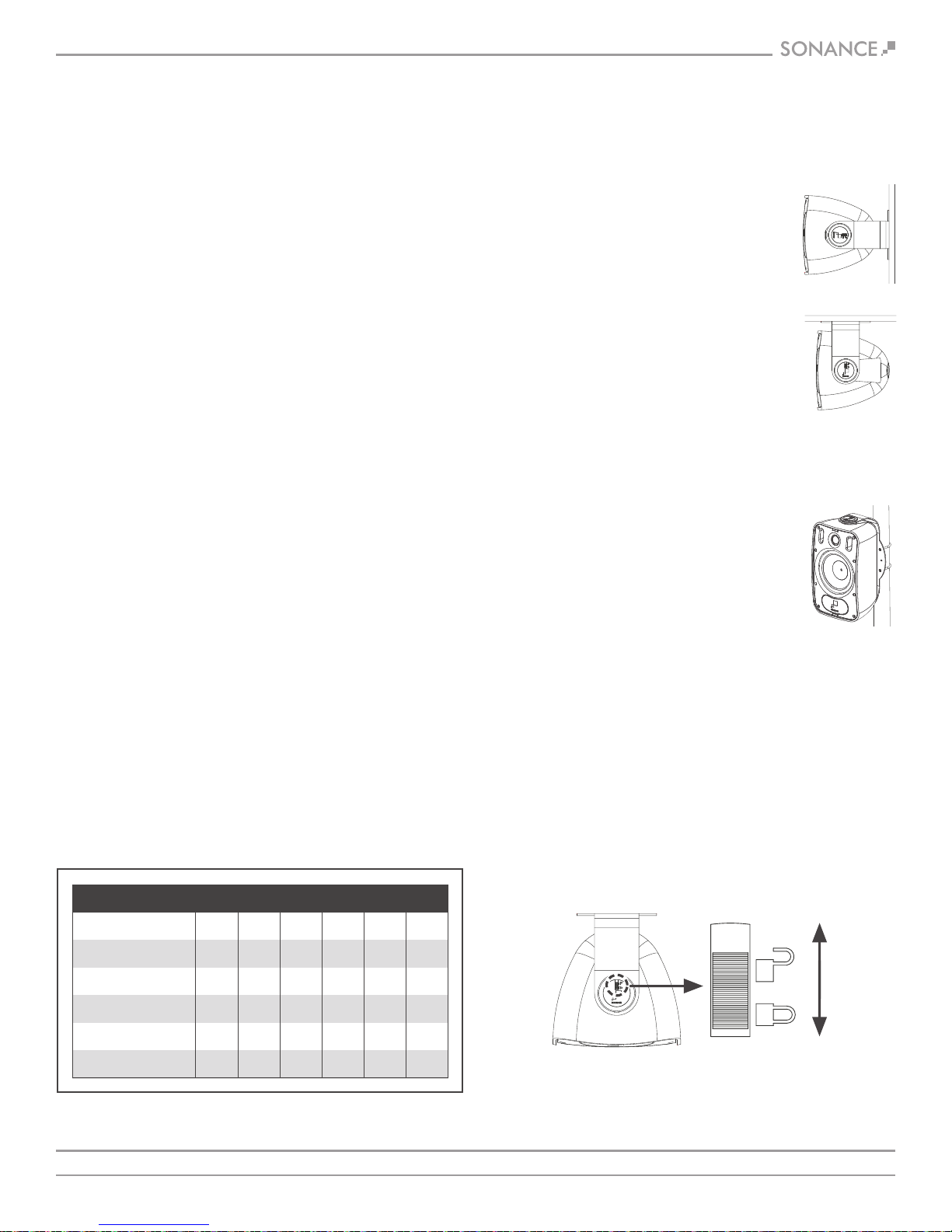
Sonance Professional Series speakers possess extremely smooth and
predictable off-axis frequency response. The FastMount mounting
system makes it easy to mount the speakers in a variety of positions
and locations (see figure 2 and 3):
WALL/CEILING MOUNTING
It is important that the bracket is securely
mounted onto a structurally sound surface,
capable of withstanding the weight of the
product and any vibration created by the
operation of the speaker. Four screws points
must be used at all times. A screw size of #14
to #20 diameter x 2” length or M6 to M8
diameter x 50mm length is recommended.
When mounting onto drywall or plasterboard,
the bracket should be affixed to a joist or stud.
When mounting onto brick or concrete, wall
plugs or concrete anchors should be used.
Wall mount
Ceiling mount
FIGURE 2:
WALL MOUNT &
CEILING MOUNT
POLE MOUNTING
To mount the speaker on a pole, 2 x U-bolts
and nuts should be used to clamp around the
pole and bolt through the 4 holes on the back
of the FastMount bracket. Spring washers or
blue thread lock are recommended to ensure
the nuts do not work loose through the
vibration of the speaker.
Pole mount
FIGURE 3:
POLE MOUNT
PIVOTING THE SPEAKERS
You can rotate the speaker in the bracket to direct the sound
towards the listeners.
1. Unlock the slide locks on the speaker pivots by moving them
towards the rear of the speaker (see figure 4).
2. Rotate the speakers to the desired position.
3. Lock the slide locks by moving them towards the front of the speaker.
UNLOCK
(towards rear
of speaker)
20 Gauge
18 Gauge
16 Gauge
14 Gauge
12 Gauge
.86 1.73 2.59 3.45 4.32 5.18
.65 1.30 1.94 2.59 3.24 3.89
.43 .85 1.28 1.71 2.14 2.56
.27 .54 .81 1.08 1.35 1.62
.17 .34 .51 .68 .85 1.02
FIGURE 1: WIRE RESISTANCE
SONANCE | PROFESSIONAL SERIES SURFACE MOUNT | INSTALLATION MANUAL 4
LOCK
(towards front
of speaker)
FIGURE 4:
LOCK AND UNLOCK SLIDE LOCKS TO PIVOT SPEAKER
Page 6

PAINTING THE GRILLES & SPEAKER SHELL
Sonance Professional Series Surface Mount speakers feature a tough
polypropylene enclosure that can be painted. Sonance recommends
using a weather-resistant outdoor paint and a spray gun.
1. If they have already been installed, remove the grilles from
the speakers.
2. To protect the speaker driver units during painting, place the
grilles on a piece of cardboard and trace around their outlines.
Then cut the cardboard just inside of the trace line and fit these
“paint plugs” into the speakers’ baffles. (Be careful not to
damage the driver components while fitting the paint plugs.)
3. Paint the speakers the desired color according to the paint
manufacturer’s instructions. Remove the paint plugs after the
paint has thoroughly dried.
4. Paint the grille separately from the speaker using very thin paint
(5:1 ratio). Avoid plugging the grille holes with excess paint.
2. Run the speaker wires from the amplifier to the speaker locations
and through the holes in the mounting brackets.
NOTE: BE SURE TO LEAVE ENOUGH WIRE AT THE SPEAKER LOCATION
TO FEED THROUGH THE TUNNEL IN THE SPEAKER ENCLOSURE AND
WIRE TO THE EUROBLOCK CONNECTOR ON THE FRONT.
3. Attach the mounting bracket
to the mounting surface using
hardware (not included) that
is appropriate for the type
of surface (see figure 7).
FIGURE 7:
ATTACH BRACKET
INSTALLING THE SPEAKERS
The best performance is obtained by placing the left and right
speakers at ear level, 6 – 10 feet apart. The speakers should be
facing the listeners. If you are mounting the speakers above or
below ear level, pivot them up or down to direct the sound towards
the listeners.
Bracket Carrying Capacity
MODEL
PS-S43T
PS-S53T
PS-S63T
PS-S83T / PS-S83WT
KGS
2.81
3.63
4.88
7.02
FIGURE 5: BRACKET CARRYING CAPACITY
1. Remove the speakers from the mounting brackets by pulling the
tabs on the front panels away from each other (see figure 6).
POUNDS
6.19
8.00
10.76
15.48
4. If the installation requires that
the speakers be mounted on
poles you can attach the bracket
to poles using 2.5” U-bolts
(not included, see figure 8).
FIGURE 8:
ATTACHING THE
BRACKET TO A POLE
5. Feed the speaker wires from the brackets into the wire entry
grommets on the backs of the speakers, through the wire tunnels
and out the openings on the speakers’ front panels (see figure 9).
• The grommet forms a water-resistant seal around the speaker wire.
• Make sure there is enough slack in the wire to allow the speaker
to pivot on the bracket.
PULL TABS AWAY FROM EACH OTHER
AND SLIDE SPEAKER OFF BRACKET
SONANCE | PROFESSIONAL SERIES SURFACE MOUNT | INSTALLATION MANUAL 5
FIGURE 6:
WIRE ENTRY GROMMET
FIGURE 9:
Page 7

INSTALLING THE SPEAKERS
Parallel Connection To Next SpeakerFrom Power Amplifier
6. Slide the speakers onto the brackets until the locks snap into place
(see figure10).
• Pull enough wire through the front of the speaker to allow
connection to the terminals.
Loop Through Connection
ATTACH SPEAKERS TO BRACKETS
FIGURE 10:
7. Connect the wires from your
amplifier to the input connector
(see figure 11).
8. Strip approximately .1875”
IN OUT
_
+
INPUT CONNECTOR
_
+
FIGURE 11:
(5mm) of the insulation off
each wire. Insert the wire into
the correct square opening on
the connector. Use a small flat
head screwdriver to tighten
the corresponding screw to
secure the wire (see figure 12).
Pin 1 + Positive In
Pin 2 - Negative In
Pin 3 + Positive Out
SECURING THE WIRE
FIGURE 12:
Pin 4 - Negative Out
When using multiple speakers you can connect the speakers either
in parallel or in the loop through method as shown (see figure 13 & 14).
From Power Amplifier
FIGURE 14: LOOP THRU CONNECTION
To Next Speaker
9. Determine the proper wattage
setting for each speaker in
the installation and set each
speaker’s transformer tap
selector (see figure 15).
TRANSFORMER TAP SELECTOR
FIGURE 15:
10. Fit the wiring terminal covers into the recesses in the speakers’
front panels (see figure 16).
• The covers should fit tightly, but can be removed and replaced
if the speakers need to be disconnected.
FIGURE 16:
CONNECTOR COVER
ATTACH THE
Parallel Connection
From Power Amplifier
FIGURE 13: PARALLEL CONNECTION
SONANCE | PROFESSIONAL SERIES SURFACE MOUNT | INSTALLATION MANUAL 6
To Next Speaker
11. Fit the grilles onto the speakers (see figure 17).
FIGURE 17:
ATTACH THE GRILLE
Page 8

PS-S43T TECHNICAL SPECIFICATIONS
LOUDSPEAKER
Frequency Range (-10dB):
Frequency Range (-3dB):
Power Capacity:
Nominal Sensitivity:
Nominal Coverage Angle:
Directivity Factor (Q):
Directivity (DI):
Rated Maximum SPL:
Rated Impedance:
Transformer Taps:
Crossover Point:
Overall Dimension:
Net Weight:
Shipping Weight:
Unit of Measure:
Color:
Grille:
57Hz – 25kHz
75Hz – 20kHz
60 Watts Continuous Program Power
30 Watts Continuous Pink Noise
87dB
90 degrees x 90 degrees coverage
7.6
8.1dB
105dB @ 1 meter (3.3 feet) average, 110dB peak
8 ohms nominal, 6 ohms minimum
70V: 30W, 15W, 7.5W and 3.8W
100V: 30W, 15W and 7.5W
3000Hz
9.25” Height x 5.47” Width x 4.8” Depth
(235mm x 139mm x 122mm)
3 lbs (1.36kg) each
14 lbs (6.35kg) pair
Pair
Black or White
Powder Coated Aluminum, Friction Fit
TRANSDUCERS
LF Driver:
HF Driver:
ENCLOSURE
Input Connectors:
Safety Agency:
Mounting Bracket:
Environmental & UV:
4” (100mm) Polypropylene Cone, Butyl Rubber Surround
1” (25mm) Cloth Dome, Ferrofluid cooled
Front-mounted four pin, Euroblock with loop output connections
UL 1480, NFPA 70
U-Bracket with Sonance FastMount
Conforms to MIL-STD-810 for humidity, salt spray, temperature,
IEC 529 IPX4 splash-proof rating
Included Accessories
• Euroblock Connector x 2
• FastMount Bracket x 2
• Terminal Cover x 2
• Grille x 2
Optional Accessories
• Replacement Grille White (pair) | 40164
• Replacement Grille Black (pair) | 40168
SONANCE | PROFESSIONAL SERIES SURFACE MOUNT | INSTALLATION MANUAL 7
Page 9

PS-S53T TECHNICAL SPECIFICATIONS
LOUDSPEAKER
Frequency Range (-10dB):
Frequency Range (-3dB):
Power Capacity:
Nominal Sensitivity:
Nominal Coverage Angle:
Directivity Factor (Q):
Directivity (DI):
Rated Maximum SPL:
Rated Impedance:
Transformer Taps:
Crossover Point:
Overall Dimension:
Net Weight:
Shipping Weight:
Unit of Measure:
Color:
Grille:
43Hz – 25kHz
70Hz – 20kHz
90 Watts Continuous Program Power
45 Watts Continuous Pink Noise
88dB
90 degrees x 90 degrees coverage
7.0
8.0dB
106dB @ 1 meter (3.3 feet) average, 113dB peak
8 ohms nominal, 6 ohms minimum
70V: 30W, 15W, 7.5W and 3.8W
100V: 30W, 15W and 7.5W
2750Hz
10.08” Height x 6.36” Width x 5.68” Depth
(256mm x 162mm x 144mm)
4 lbs (1.81kg) each
16 lbs (7.23kg) pair
Pair
Black or White
Powder Coated Aluminum Friction Fit
TRANSDUCERS
LF Driver:
HF Driver:
ENCLOSURE
Input Connectors:
Safety Agency:
Mounting Bracket:
Environmental & UV:
5.25” (130mm) Polypropylene Cone, Butyl Rubber Surround
1” (25mm) Cloth Dome, Ferrofluid cooled
Front-mounted four pin, Euroblock with loop output connections
UL 1480, NFPA 70
U-Bracket with Sonance FastMount
Conforms to MIL-STD-810 for humidity, salt spray,
temperature, IEC 529 IPX4 splash-proof rating
Included Accessories
• Euroblock Connector x 2
• FastMount Bracket x 2
• Terminal Cover x 2
• Grille x 2
Optional Accessories
• Replacement Grille White (pair) | 93162
• Replacement Grille Black (pair) | 93163
SONANCE | PROFESSIONAL SERIES SURFACE MOUNT | INSTALLATION MANUAL 8
Page 10

PS-S63T TECHNICAL SPECIFICATIONS
LOUDSPEAKER
Frequency Range (-10dB):
Frequency Range (-3dB):
Power Capacity:
Nominal Sensitivity:
Nominal Coverage Angle:
Directivity Factor (Q):
Directivity (DI):
Rated Maximum SPL:
Rated Impedance:
Transformer Taps:
Crossover Point:
Overall Dimension:
Net Weight:
Shipping Weight:
Unit of Measure:
Color:
Grille:
49Hz – 25kHz
65Hz – 20kHz
120 Watts Continuous Program Power
60 Watts Continuous Pink Noise
88dB
90 degrees x 90 degrees coverage
6.5
7.9dB
108dB @ 1 meter (3.3 feet) average, 116dB peak
8 ohms nominal, 6 ohms minimum
70V: 60W, 30W, 15W and 7.5W
100V: 60W, 30W and 15W
2750Hz
12.14” Height x 7.51” Width x 6.86” Depth
(308mm x 191mm x 174mm)
5 lbs (2.27kg) each
19 lbs (8.61kg) pair
Pair
Black or White
Powder Coated Aluminum Friction Fit
TRANSDUCERS
LF Driver:
HF Driver:
ENCLOSURE
Input Connectors:
Safety Agency:
Mounting Bracket:
Environmental & UV:
6.5” (165mm) Polypropylene Cone, Butyl Rubber Surround
1” (25mm) Cloth Dome, Ferrofluid cooled
Front-mounted four pin, Euroblock with loop output connections
UL 1480, NFPA 70
U-Bracket with Sonance FastMount
Conforms to MIL-STD-810 for humidity, salt spray,
temperature, IEC 529 IPX4 splash-proof rating
Included Accessories
• Euroblock Connector x 2
• FastMount Bracket x 2
• Terminal Cover x 2
• Grille x 2
Optional Accessories
• Replacement Grille White (pair) | 93164
• Replacement Grille Black (pair) | 93165
SONANCE | PROFESSIONAL SERIES SURFACE MOUNT | INSTALLATION MANUAL 9
Page 11

PS-S83T TECHNICAL SPECIFICATIONS
LOUDSPEAKER
Frequency Range (-10dB):
Frequency Range (-3dB):
Power Capacity:
Nominal Sensitivity:
Nominal Coverage Angle:
Directivity Factor (Q):
Directivity (DI):
Rated Maximum SPL:
Rated Impedance:
Transformer Taps:
Crossover Point:
Overall Dimension:
Net Weight:
Shipping Weight:
Unit of Measure:
Color:
Grille:
41Hz – 25kHz
55Hz – 20kHz
160 Watts Continuous Program Power
80 Watts Continuous Pink Noise
90dB
90 degrees x 90 degrees coverage
7.6
8.1dB
110dB @ 1 meter (3.3 feet) average, 116dB peak
8 ohms nominal, 6 ohms minimum
70V: 60W, 30W, 15W and 7.5W
100V: 60W, 30W and 15W
2750Hz
14.02” Height x 9.01” Width x 8.58” Depth
(356mm x 229mm x 218mm)
10 lbs (4.53kg) each
25 lbs (11.34kg) pair
Pair
Black or White
Powder Coated Aluminum Friction Fit
TRANSDUCERS
LF Driver:
HF Driver:
ENCLOSURE
Input Connectors:
Safety Agency:
Mounting Bracket:
Environmental & UV:
8” (203mm) Polypropylene Cone, Butyl Rubber Surround
1” (25mm) Cloth Dome, Ferrofluid cooled
Front-mounted four pin, Euroblock with loop output connections
UL 1480, NFPA 70
U-Bracket with Sonance FastMount
Conforms to MIL-STD-810 for humidity, salt spray,
temperature, IEC 529 IPX4 splash-proof rating
Included Accessories
• Euroblock Connector x 2
• FastMount Bracket x 2
• Terminal Cover x 2
• Grille x 2
Optional Accessories
• Replacement Grille White (pair) | 93166
• Replacement Grille Black (pair) | 93167
SONANCE | PROFESSIONAL SERIES SURFACE MOUNT | INSTALLATION MANUAL 10
Page 12

PS-S83WT TECHNICAL SPECIFICATIONS
LOUDSPEAKER
Frequency Range (-10dB):
Frequency Range (-3dB):
Power Capacity:
Nominal Sensitivity:
Nominal Coverage Angle:
Directivity Factor (Q):
Directivity (DI):
Rated Maximum SPL:
Rated Impedance:
Transformer Taps:
Crossover Point:
Overall Dimension:
Net Weight:
Shipping Weight:
Unit of Measure:
Color:
Grille:
32Hz – 300Hz
50Hz – 150Hz
200 Watts Continuous Program Power
125 Watts Continuous Pink Noise
89dB
180 degrees x 180 degrees coverage
N/A
N/A
110dB @ 1 meter (3.3 feet) average, 116dB peak
8 ohms nominal, 6 ohms minimum
70V: 120W, 60W, 30W and 15W
100V: 120W, 60W and 30W
150Hz
14.02” Height x 9.01” Width x 8.58” Depth
(356mm x 229mm x 218mm)
12 lbs (5.44kg) each
18 lbs (8.61kg) each
Each
Black or White
Powder Coated Aluminum Friction Fit
TRANSDUCERS
LF Driver:
HF Driver:
ENCLOSURE
Input Connectors:
Safety Agency:
Mounting Bracket:
Environmental & UV:
8” (203mm) Polypropylene Cone, Butyl Rubber Surround
N/A
Front-mounted four pin, Euroblock with loop output connections
UL 1480, NFPA 70
U-Bracket with Sonance FastMount
Conforms to MIL-STD-810 for humidity, salt spray,
temperature, IEC 529 IPX4 splash-proof rating
Included Accessories
• Euroblock Connector x 1
• FastMount Bracket x 1
• Terminal Cover x 1
• Grille x 1
Optional Accessories
• Replacement Grille White (pair) | 93166
• Replacement Grille Black (pair) | 93167
SONANCE | PROFESSIONAL SERIES SURFACE MOUNT | INSTALLATION MANUAL 11
Page 13

CERTIFICATIONS
TECHNICAL ASSISTANCE AND SERVICE
SAFETY AGENCY COMPLIANCE
Sonance Professional Series loudspeakers models PS-S43T, PS-S53T,
PS-S63T, PS-S83T & PS-S83WT meet the following standards:
UL 1480: Listed Standard For Safety For Speakers for
Fire Alarm, Emergency, and Commercial and Professional Use.
NFPA 70: 2002 National Electrical Code
ENVIRONMENTAL AND UV: Conforms to Mil Spec 810 for
humidity, salt spray, temperature, IEC 529 IP-X4 splash-proof rating.
The Technical Assistance Department at Sonance is available at
(949) 492-7777 to answer any questions concerning the operation
and installation of your speakers between the hours of 7:00 AM and
5:00 PM Pacific time, Monday through Friday, except holidays.
In the event your unit should need repair or service, you may return
the unit to your authorized dealer or use the following guidelines:
PLEASE KEEP ORIGINAL PACKAGING WHEN POSSIBLE.
1. Be prepared to state the model number and / or serial number,
date of purchase, and dealer’s name and address when calling.
2. Contact Sonance directly at (949) 492-7777 or at www.sonance.com
YOU MUST HAVE PRIOR AUTHORIZATION TO RETURN YOUR UNIT.
3. If you are returning the product directly to Sonance, call us to
obtain a return authorization number before shipping.
4. Ship the product via United Parcel Service, Federal Express,
or other package delivery service. Please do not use the
U.S. Postal Service.
5. Write the return authorization number on the outside of the box.
6. Ship to:
Attn: Quality Assurance Department
Sonance
212 Avenida Fabricante
San Clemente, CA 92672-7531
SONANCE | PROFESSIONAL SERIES SURFACE MOUNT | INSTALLATION MANUAL 12
Page 14
WARRANTY, REMEDY, EXCLUSIONS AND LIMITATIONS (U.S. ONLY)
Limited Warranty
Sonance warrants this product to the original purchaser to be free from defects in material and workmanship, under normal use and
conditions, for a period of five (5) years from the date of original purchase as shown on the invoice.
The foregoing exclusive warranty gives you specific legal rights, and you may have other rights, which vary from state to state. This warranty
applies exclusively to the original purchaser.
The exclusive warranty does not apply and is ineffective if:
1. The invoice fails to establish that the product was purchased from an authorized Sonance dealer or distributor;
2. The product was subjected to misuse, neglect, accident, or improper installation.
[Damage to the product was caused by accident, abuse, or misuse];
3. The product was modified, altered, or repaired by unauthorized personnel; or
4. The unit was not used as described in the installation and operating instructions.
Exclusive Remedy
Sonance agrees, at its option during the five (5) year warranty period, to repair any defect in material or workmanship or to furnish an equal
product in exchange without charge to the purchaser, subject to verification of the defect and proof of the date of purchase.
Exclusions
TO THE EXTENT PERMITTED BY LAW, THE WARRANTY SET FORTH ABOVE IS IN LIEU OF, AND EXCLUSIVE OF, ALL OTHER WARRANTIES, EXPRESS
OR IMPLIED, AND IS THE SOLE AND EXCLUSIVE WARRANTY PROVIDED BY SONANCE. ALL OTHER EXPRESS AND IMPLIED WARRANTIES,
INCLUDING THE IMPLIED WARRANTIES OF MERCHANTABILITY, IMPLIED WARRANTY OF FITNESS FOR USE, AND IMPLIED WARRANTY OF
FITNESS FOR A PARTICULAR PURPOSE ARE SPECIFICALLY EXCLUDED.
No one is authorized to make or modify any warranties on behalf of Sonance. The warranty stated above is the sole and exclusive remedy
and Sonance’s performance shall constitute full and final satisfaction of all obligations, liabilities and claims with respect to the Product.
IN ANY EVENT, SONANCE SHALL NOT BE LIABLE FOR CONSEQUENTIAL, INCIDENTAL, ECONOMIC, PROPERTY, BODILY INJURY, OR
PERSONAL INJURY DAMAGES ARISING FROM THE PRODUCT, ANY BREACH OF THIS WARRANTY OR OTHERWISE.
This warranty statement gives you specific legal rights, and you may have other rights which vary from state to state. Some states do not allow
the exclusion of implied warranties or limitations of remedies, so the above exclusions and limitations may not apply. If your state does not
allow disclaimer of implied warranties, the duration of such implied warranties is limited to period of Sonance’s express warranty.
Warranty Exclusions and Damage Limitations
Additional Limitations and Exclusions from Warranty Coverage: The warranty described above is non-transferable, applies only to the initial
installation of the Product, does not include installation of any repaired or replaced Product, does not include damage to allied or associated
equipment which may result for any reason from use with this Product, and does not include labor or parts caused by accident, disaster,
negligence, improper installation, misuse (e.g. overdriving the amplifier or speaker, excessive heat or cold or humidity, outdoor installation),
or from service or repair which has not been authorized by Sonance.
Obtaining Authorized Service: To qualify for the warranty, you must contact your authorized Sonance Dealer/Installer or call Sonance
Customer Service at (949) 492-7777 within the warranty period, must obtain a return merchandise number (RMA), and must deliver the
Product to Sonance shipping prepaid during the warranty period, together with the original sales receipt, or invoice or other satisfactory
proof of purchase.
©2017 Sonance. All rights reserved. Sonance and FastMount are registered trademarks of Dana Innovations.
Due to continuous product improvement, all features and specifications are subject to change without notice.
For the latest Sonance product specification information visit our website: www.sonance.com
SONANCE • 212 Avenida Fabricante • San Clemente, CA 92672-7531 USA
SONANCE | PROFESSIONAL SERIES SURFACE MOUNT | INSTALLATION MANUAL 13
(949) 492-7777 • FAX: (949) 361-5151
www.sonance.com/professionalseries
01.11.17
 Loading...