

Page 1
INSTRUCTION MANUAL
LS10SUB IN-GROUND SUBWOOFER
Introduction
Thank you for purchasing a SLS Subwoofer. When properly installed,
this subwoofer will provide you with years of outdoor entertainment
pleasure. To get the most out of your new subwoofer, please read
this manual thoroughly before you begin installation.
Box Contents
SLS In-ground subwoofer boxes contain:
(1) In-ground subwoofer
(1) Dark brown canopy with ABS tube
(1) Rubber elbow
(2) Stainless steel hose clamps
(2) Silicon filled wire nuts
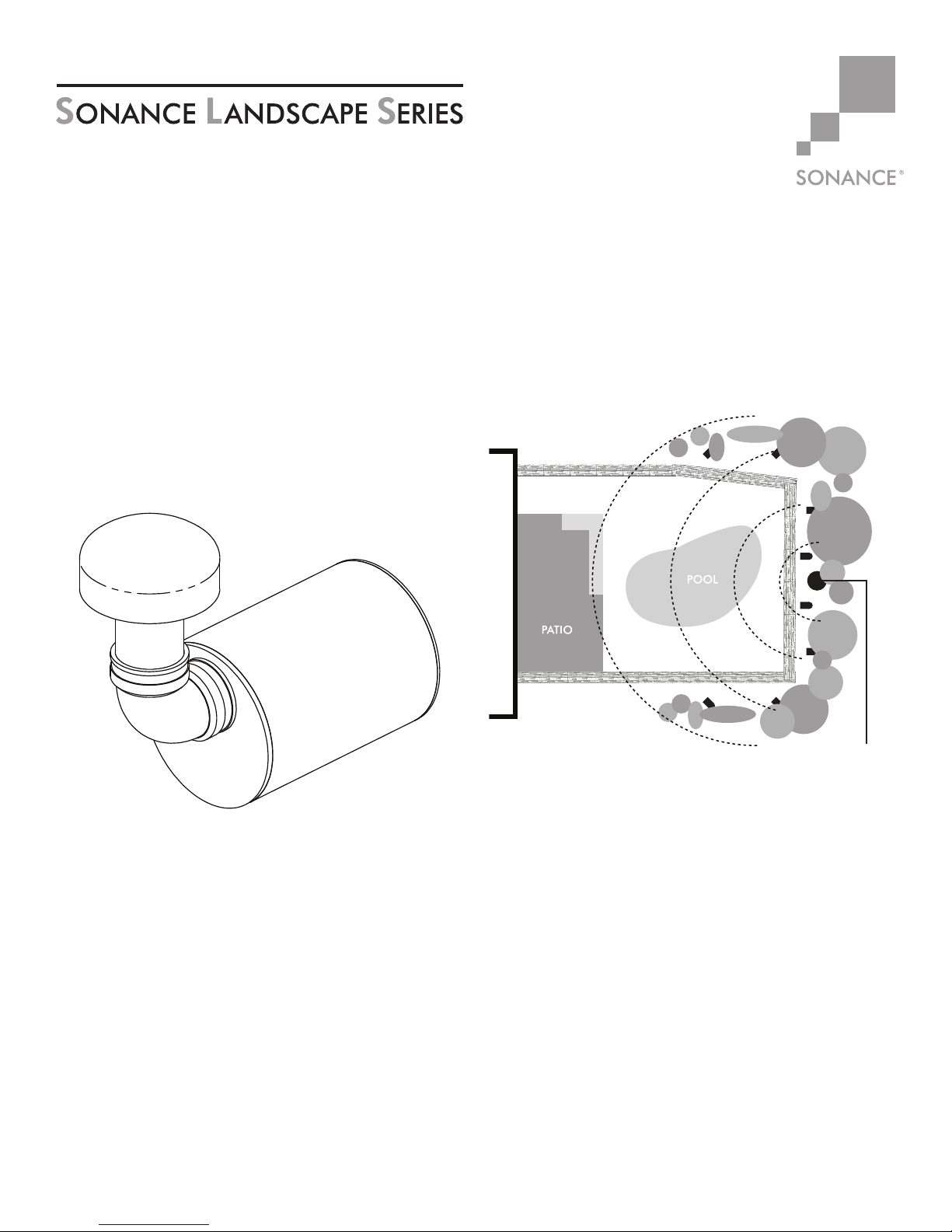
AS A GENERAL GUIDELINE, (1) SUBWOOFER WILL COVER
ABOUT 2000 SQUARE FEET OF LISTENING AREA
Figure 1 shows the SLS placed along the perimeter of the
entertainment area.
Select a central location for the subwoofer if using only one
subwoofer (see Figure 1) if using multiple subwoofers, select
locations that are the same distance from the main listening area.
In-Ground Subwoofer
Subwoofer Location Selection
The SLS is designed to deliver a seamless, evenly dispersed sound
field in an ‘open air’ environment. An array of multiple Satellite
speakers and Subwoofers should be strategically placed to
minimize ‘hot spots’ and ‘nulls’ as you move around the outdoor
entertainment area.
Figure 1 Subwoofer
Sonamp DSP 2-750
Amplifier Power Planning
The maximum number of satellites and subwoofers that can
be used in a system will depend on the amplifier power,
refer to the SLS wattage calculator on the Sonance website
(www.sonance.com/outdoor/sonance-landscape-series/subwoofers).
1
Page 2
I N S TA L L AT I O N OP T IO NS
Waterproof
From Speaker To Amplifie
r
SONANCE LANDSCAPE SERIES LS10SUB INSTRUCTION MANUAL
Subwoofer Installation
70 volt audio systems allow for speakers to be daisy chained
together. In a typical system with one zone of audio you simply run a
stereo or 4 conductor wire from the amplifier to the closest speaker.
Once you have designated your first speaker as either left or right,
continue alternating the wires between the left and right channels
creating a daisy chain of stereo satellites. The Subwoofer can be
wired anywhere in the chain. See figure 5.
Note: Sonance strongly recommends the use of 14
gauge, or larger, direct burial grade wire.
Caution: The amplifier should not be connected to
AC power until all connections are completed. High
power 70volt amplifiers present a serious shock
hazard. Do not connect speaker wires to the amplifier
until all other connections are completed.
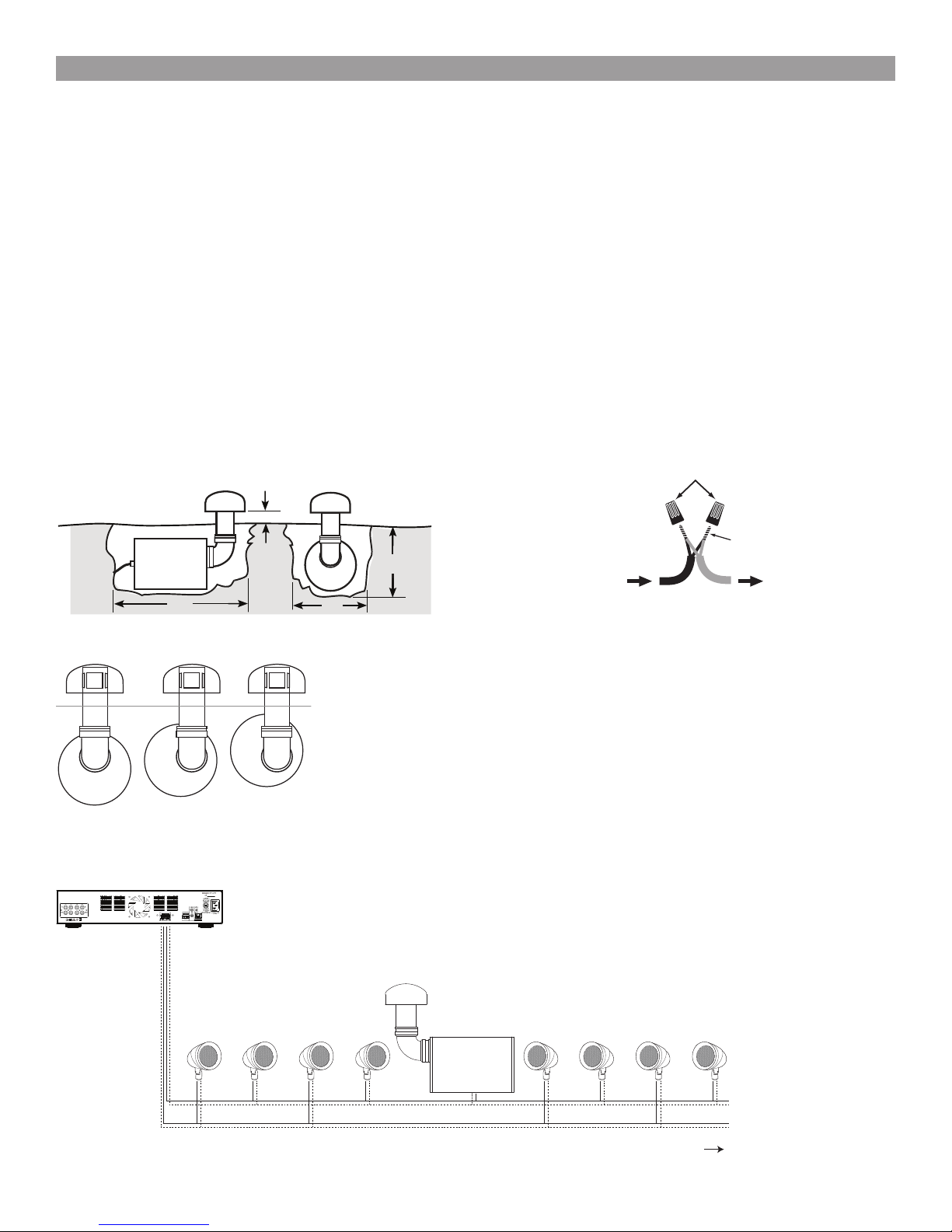
1. Locate the subwoofer in an area that will not flood with standing
water.
2. Dig the hole using the guide. See figure 2
LS10SUB: A=4” B=26” C=16” D=13”-16”
Note: (for variable depth see Figure 3 below)
A
D
3. Prepare a ‘bed’ for the subwoofer that is reasonably free of
voids and large rocks.
4. Install and secure the rubber elbow onto the canopy and ABS
tube subassembly using one of the supplied hose clamps.
5. Install the rubber elbow and canopy assembly on the subwoofer
enclosure; do not tighten the second hose clamp at this point.
When placing the rubber elbow onto the subwoofer, it is
recommended to add General Purpose Marine Grease to the
inside of the elbow. This grease is available under the brand
name Sta-Lube. This lube will act like a water barrier and ensure
that water won’t enter in through the elbow connection.
6. Place the subwoofer into the ground.
7. Rotate the cabinet as required so that the bottom of the canopy
will be 4” above the finished grade after backfill.
8. Once the subwoofer is in the correct location tighten the hose clamp
at the connection between the enclosure and the rubber elbow.
9. Dig a 4” – 5” deep trench to run the speaker wires in.
10. Run the wire through the trench from your amplifier to the first
speaker location.
Wire Nuts
Positive
+
Negative
-
Twist
Wires
Together
B
Figure 2
Figure 3
SLS Wiring Diagram 70V
C
GROUND
LEVEL
SONAMP DSP 2-750 Amplifier
LS47SATs & LS10SUB
LeftLeft RightRight LeftLeft RightRight
Figure 4
11. Connect the direct burial wire to each speaker wire, connections
should be made with either silicone filled wire connectors or
appropriate junction boxes. See Figure 4.
IMPORTANT: Be sure not to let any stray ‘+’ and ‘–’
strands touch each other. Touching strands can cause
a short-circuit that could damage your amplifier.
Note: Confirm that you have connected speaker
“+” to amplifier “+” and speaker “–” to amplifier
“–”.
12. After all the speakers connections are completed, connect the
wires to your amplifier. See Figure 5 for reference.
13. Turn your amplifier on and test the system with your favorite
music. If the speakers are operating properly, refill the wire
trench and enjoy your new speakers.
Note: The subwoofer can
be connected at any point
in the daisy chain.
Figure 5
ExpandableConfiguration: 4 SATs to 1 SUB or up to 8 SATs to 1 SUB
2
Page 3

SONANCE LANDSCAPE SERIES LS10SUB INSTRUCTION MANUAL
Specifications
LS10SUB
Woofer: 10” (254mm) polypropylene
cone with a rubber surround
Frequency Response: 35Hz – 80Hz ±3dB
Power Required: 100 watts
Enclosure Material: 1/2” (HDPE) Non-corrosive
sealed enclosure
Crossover: 100Hz
Available Finishes: Black enclosure,
Dark brown textured canopy
Dimensions: Overall
Length: 26 1/4” (667mm)
Adjustable Height
Standard Canopy Position
Height: 24 3/8” (619mm)
Alternate Canopy Position
Height: 18 1/4” (464mm)
Woofer Enclosure
Length: 15 3/4” (400mm)
Diameter: 12 1/2” (318mm)
Canopy
Height: 4 3/4” (121mm)
Diameter: 9 1/2” (241mm)
Woofer
Enclosure
Diameter
Canopy
Height
Woofer Enclosure
Length
Overall
Length
Canopy
Diameter
Overall
Adjustable
Height
Standard
Position
Overall
Adjustable
Height
Alternate
Position
Alternate Canopy PositionStandard Canopy Position
3
Page 4

SONANCE LANDSCAPE SERIES LS10SUB INSTRUCTION MANUAL
LIMITED FIVE (5) YEAR WARRANTY
Sonance warrants to the first end-user purchaser that this Sonance-brand product (“Product”), when purchased from an authorized Sonance
Dealer/Distributor, will be free from defective workmanship and materials for the period stated below. Sonance will at its option and expense
during the warranty period, either repair the defect or replace the Product with a new or remanufactured Product or a reasonable equivalent.
EXCLUSIONS
TO THE EXTENT PERMITTED BY LAW, THE WARRANTY SET FORTH ABOVE IS IN LIEU OF, AND EXCLUSIVE OF, ALL
OTHER WARRANTIES, EXPRESS OR IMPLIED, AND IS THE SOLE AND EXCLUSIVE WARRANTY PROVIDED BY SONANCE.
ALL OTHER EXPRESS AND IMPLIED WARRANTIES, INCLUDING THE IMPLIED WARRANTIES OF MERCHANTABILITY,
IMPLIED WARRANTY OF FITNESS FOR USE, AND IMPLIED WARRANTY OF FITNESS FOR A PARTICULAR PURPOSE ARE
SPECIFICALLY EXCLUDED.
No one is authorized to make or modify any warranties on behalf of Sonance. The warranty stated above is the sole and exclusive remedy
and Sonance’s performance shall constitute full and final satisfaction of all obligations, liabilities and claims with respect to the Product.
IN ANY EVENT, SONANCE SHALL NOT BE LIABLE FOR CONSEQUENTIAL, INCIDENTAL, ECONOMIC, PROPERTY,
BODILY INJURY, OR PERSONAL INJURY DAMAGES ARISING FROM THE PRODUCT, ANY BREACH OF THIS WARRANTY
OR OTHERWISE.
This warranty statement gives you specific legal rights, and you may have other rights which vary from state to state. Some states do not allow
the exclusion of implied warranties or limitations of remedies, so the above exclusions and limitations may not apply. If your state does not
allow disclaimer of implied warranties, the duration of such implied warranties is limited to period of Sonance’s express warranty.
Your Product Model and Description: SLS LS10SUB In-Ground Subwoofer
Warranty Period for this Product: Five (5) years from the date on the original sales receipt or invoice or other satisfactory proof of purchase.
Additional Limitations and Exclusions from Warranty Coverage: The warranty described above is non-transferable, applies only to the
initial installation of the Product, does not include installation of any repaired or replaced Product, does not include damage to allied or
associated equipment which may result for any reason from use with this Product, and does not include labor or parts caused by accident,
disaster, negligence, improper installation, misuse (e.g. overdriving the amplifier or speaker, excessive heat, cold or humidity), or from
service or repair which has not been authorized by Sonance. Obtaining Authorized Service: To qualify for the warranty, you must contact your
authorized Sonance Dealer/Installer or call Sonance Customer Service at (800) 582-0772 within the warranty period, must obtain a return
merchandise number (RMA), and must deliver the Product to Sonance shipping prepaid during the warranty period, together with the original
sales receipt, or invoice or other satisfactory proof of purchase.
©2015 Sonance. All rights reserved. Sonance is a registered trademarks of Dana Innovations. Patent Pending.
Due to continuous product improvement, all features and specifications are subject to change without notice.
For the latest Sonance product specification information visit our website: www.sonance.com
SONANCE • 212 Avenida Fabricante • San Clemente, CA 92672-7531 USA
(949) 492-7777 • FAX: (949) 361-5151
www.sonance.com
33-5512 03.13.15
 Loading...