

Page 1
INTRODUCTION
Thank you for purchasing the LS2/LR2 balanced line sender/receiver. The LS2
converts line-level audio to a balanced line configuration; the LR2 converts
balanced line audio back to line-level.
When connected with high-quality 4-conductor shielded audio wire (such as
Sonance MediaLinQ), the LS2 and LR2 form a system designed to provide
high-quality/low-loss audio for long-distance requirements. They can send
low-level audio signals long distances and in close proximity to sources of
noise interference without inducing noise or high-frequency roll-off. As a
general rule of thumb, a balanced signal should be used for anything but short
lengths of audio cable (under 20 feet) and wherever the possibility of signal
interference is likely (i.e. where the audio signal passes near dimmers, transformers, fluorescent and neon lights, or along the same pathways as house
current). The active LS2 circuitry sends the signal to the LR2, virtually eliminating any noise picked up through the wire during the signal transfer, leaving only the original signal.
The LS2 and LR2 are always used in conjunction with each other, except when
used in conjunction with equipment with balanced inputs or outputs (such as
professional sound or recording equipment). In this manner,the LS2 could be
used as an unbalanced-to-balanced converter and the LR2 could be used as a
balanced-to-unbalanced converter. The LS2 can also be used with the 275 SE
and ASAP2 SAT amplifiers with an LR1 SAT module (part# 91815) installed.
LS2/LR2 NEW FEATURES
The LS2 and LR2 incorporate several new features that improve their
performance and installability:
• The LS2 and LR2 operate on a single-output 12V DC power supply, and can also be
powered directly by 12V sources in cars, boats or RV installations. The LS2 and LR2
power inputs have reverse polarity protection.
•
DC In
and
DC Out
connections allow multiple units to share a single power supply.
• The LS2 and LR2
Balanced Input
and
Balanced Output
connectors are removable
quick-toggle RIA connectors.
• The LS2 and LR2 chassis have recessed mounting holes that allow them to
easily be wall-mounted using two screws.
• The LS2 and LR2 chassis’ are compatible with 3” TK-series SnapTrack
®
from Augat.
INSTRUCTION MANUAL
LS2 and LR2 INDUSTRY UPGRADE
BALANCED LINE SENDER AND RECEIVER
OUTPUT
BALANCED
INPUT
UNBALANCED
BALANCED LINE SENDER
+L– –R+
SH
LR
IN
OUT
12VDC
150mA
LS2
IN
OUT
12VDC
150mA
LR2
INPUT
UNBALANCED
OUTPUT
BALANCED
BALANCED LINE RECEIVER
+L– –R+
SH
LR
IN
OUT
12VDC
150mA
LR2
INPUT
UNBALANCED
OUTPUT
BALANCED
BALANCED LINE RECEIVER
+L– –R+SH
LR
IN
OUT
12VDC
150mA
LR2
INPUT
UNBALANCED
OUTPUT
BALANCED
BALANCED LINE RECEIVER
+L– –R+SH
LR
Volume
Control
Power Amplifier
Speakers
Whole-Home System
Preamp/Controller
Zone 1
LS2
Sender
LR2
Receiver
LR2
Receiver
LR2
Receiver
Volume
Control
Power Amplifier
Speakers
Zone 3
Volume
Control
Power Amplifier
Speakers
Zone 2
From
Preamp
Output
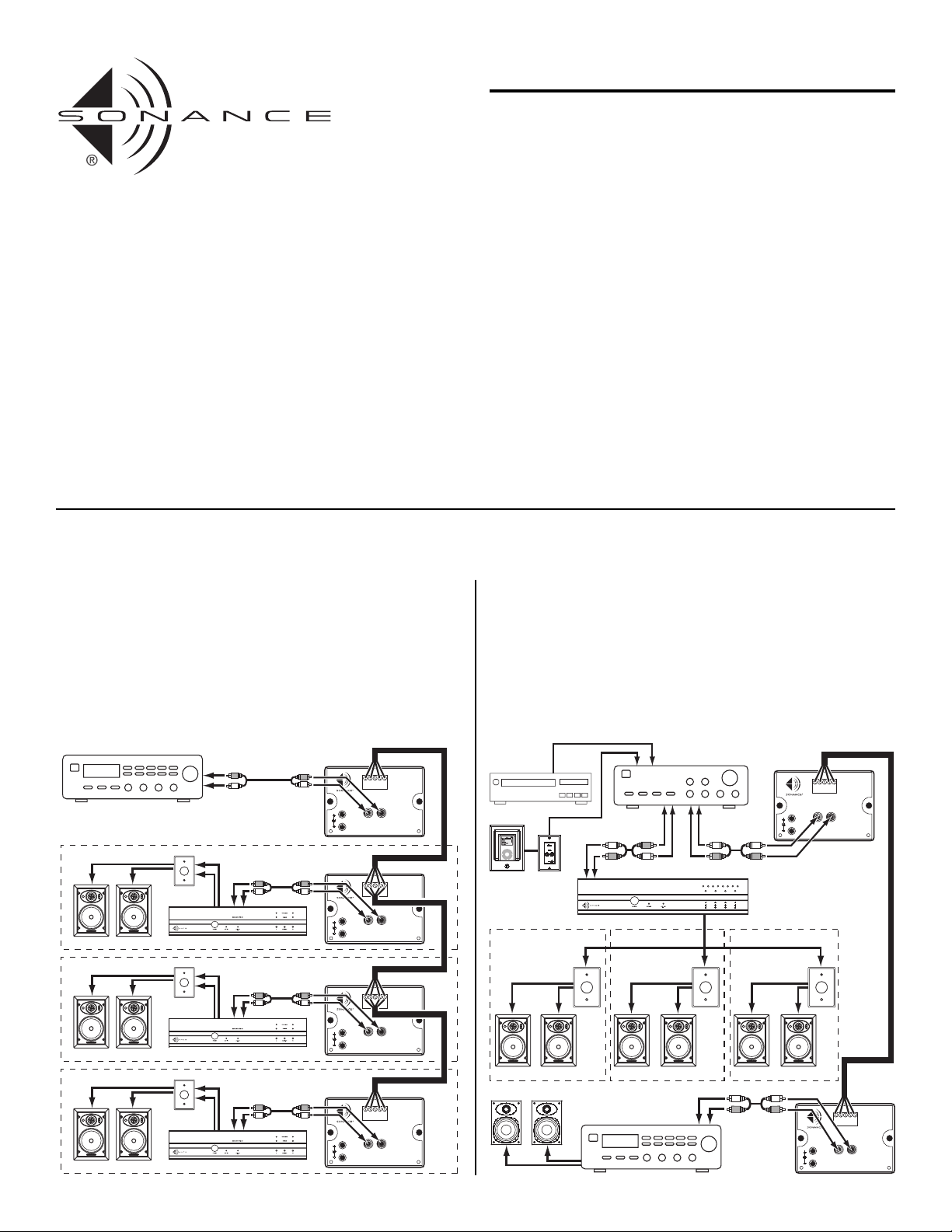
APPLICATIONS
Here are two examples of how the LS2 and LR2 can be used in different system configurations:
Illustration 1: Locating Amplifiers in Local Zones
SONAMP 875D SE
PROTECTION
AUTO-ON
BBE ON
ACTIVE
LR
1–2 3–4 5–6 7–8
LRLRLR
OUTPUT
BALANCED
INPUT
UNBALANCED
BALANCED LINE SENDER
+L– –R+
SH
LR
IN
OUT
12VDC
150mA
LS2
IN
OUT
12VDC
150mA
LR2
INPUT
UNBALANCED
OUTPUT
BALANCED
BALANCED LINE RECEIVER
+L– –R+
SH
LR
MENU
Bedroom System
Receiver
Speakers Speakers Speakers
Bedroom Speakers
From
Main
Outputs
From
Tape Record
Outputs
To
Aux
Inputs
Whole-Home
System Preamp
CD Changer
iPort with iPod
Whole-Home
System Amplifier
LS2
Sender
LR2
Receiver
Volume
Control
Volume
Control
Volume
Control
Zone 1 Zone 2 Zone 3
1
Illustration 2: Connecting Remote Sources to a Local System
Locating Amplifiers in Local Zones
(see
Illustration 1
)
Locating power amplifiers close to the speakers they drive minimizes power
loss through long speaker wire runs. The LS2 converts the preamp output to
a balanced signal, allowing it to be sent long distances to local amplifiers
without noise interference or high-frequency loss. Local LR2s convert the
balanced signal back to an unbalanced line-level audio for the amplifiers.
The LS2’s balanced output can be “daisy-chained” to up to nine (9) LR2s.
Connecting Remote Sources to a Local System
(see
llustration 2
)
A whole-home audio system can be connected to a local system, allowing its
sources to become sources for the local system. The LS2 converts a preamp
output or tape record output from the whole-home preamp/controller to a
balanced signal that can then be sent a long distance. An LR2 at the local
system converts the balanced signal to a line-level signal that is then connected
to an input on the local system.
Page 2
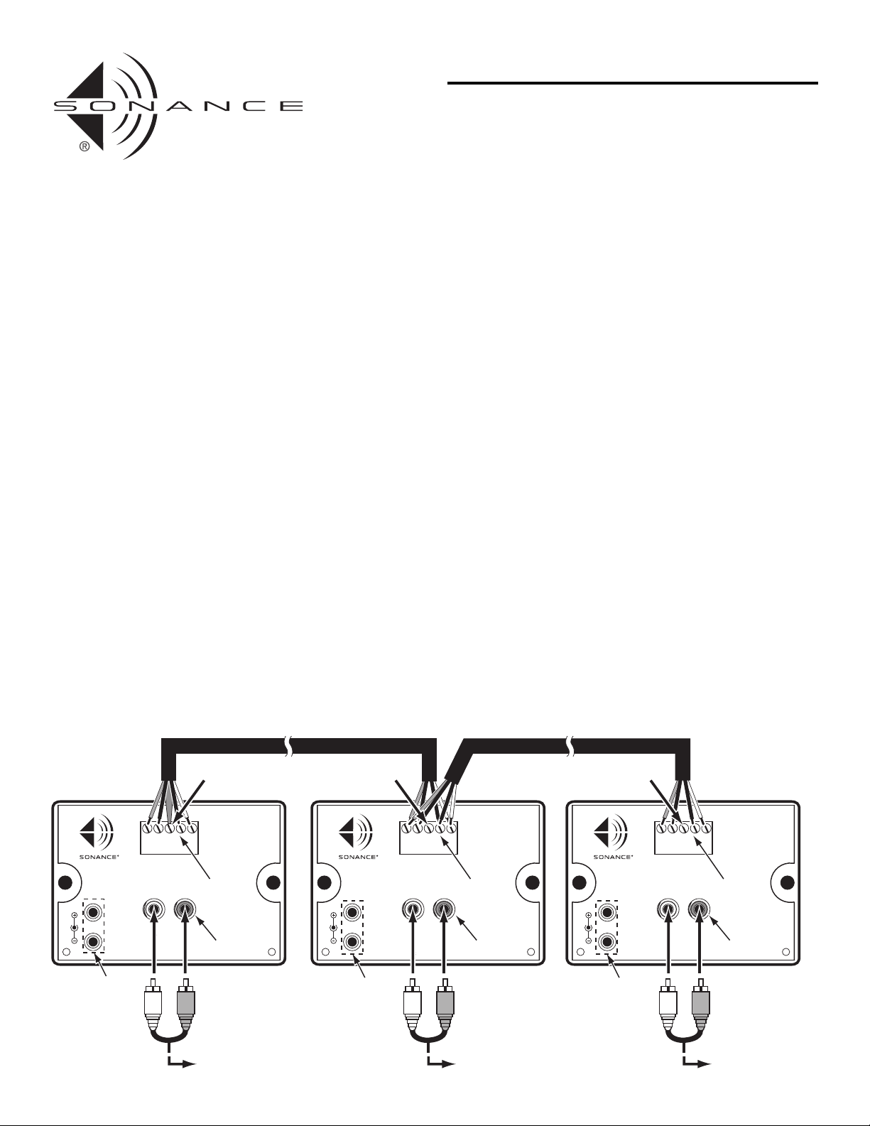
CONNECTING THE LS2 AND LR2 (see
Illustration 3
)
IMPORTANT: Make sure all source components and power amplifiers are
turned OFF before making any connections.
Do not plug the power supply into a wall outlet until all connections have
been made.
1. Use a stereo RCA cord to connect the audio source component to the LS2’s
Unbalanced Input.
2. Use shielded 4-conductor wire,such as Sonance MediLinQ 22/4 audio wire
(part #91874), to connect the LS2’s Balanced Output terminals to the LR2’s
Balanced Input terminals as shown in Illustration 3. The maximum length
of 4-conductor wire that can be used is 1,000 feet.
• Make sure to connect the “+” terminals together and the “–” terminals
together and to connect Left to Left and Right to Right.
IMPORTANT: To minimize ground noise, connect the wire shield ONLY
to the ‘
SH’
terminal on the LS2 sender. DO NOT connect the wire shield
to the LR2 receiver. Make sure not to allow the shield to touch any of the
adjacent wires.
• If you’re sending the LS2’s signal to multiple LR2s, ‘daisy-chain’ the LR2s
together using lengths of 4-conductor shielded audio cable. You can feed
up to nine (9) LR2 receivers from a single LS2 sender. The maximum
length of 4-conductor wire that can be used is 1,000 feet total.
• Do not connect the wire shield to any of the LR2 receivers.
4. Connect the included PS-1 power supplies to the LS2’s and LR2’s 12V DC
jacks and plug them into non-switched AC outlets that supply continuous
current.
• You can power up to nine (9) LR2 receiver units from the LS2’s single
power supply. Connect a power supply cable with standard 2.1mm
internal diameter connectors between the LS2’s 12V DC Out jack and the
first LR2’s 12V DC In jack,and then daisy-chain the next LR2’s 12V DC In
jack to the first LR2’s 12V DC Out jack using another power supply cable
(up to 9 total LR2s). Repeat for all LR2s.
SPECIFICATIONS
(0dB ref = 0.775V)
THD + Noise: <01%, 20Hz – 20kHz
Signal-to-Noise Ratio: >-100dB (IHF-A wtd.)
CMRR (LR2): >98dB (20Hz – 5kHz); >75dB (5kHz – 20kHz)
Frequency Response: 20Hz – 20kHz ±0.2dB
Input Impedance: 47k ohms (LS2 unbalanced inputs)
Output Impedance: 600 ohms (LR2 unbalanced outputs)
Power Consumption: 55mA ±5% @ 12VDC (LS2);
30mA ±5% @ 12VDC (LR2)
Dimensions (WxHxD): 4” x 2” x 3” (102mm x 51mm x 76mm)
INSTRUCTION MANUAL
LS2 and LR2 INDUSTRY UPGRADE
BALANCED LINE SENDER AND RECEIVER
IN
OUT
12VDC
150mA
LR2
INPUT
BALANCED
OUTPUT
UNBALANCED
BALANCED LINE RECEIVER
+L– –R+SH
LR
IN
OUT
12VDC
150mA
LR2
INPUT
BALANCED
OUTPUT
UNBALANCED
BALANCED LINE RECEIVER
+L– –R+SH
LR
OUTPUT
BALANCED
INPUT
UNBALANCED
BALANCED LINE SENDER
+L– –R+SH
LR
IN
OUT
12VDC
150mA
LS2
Connect
Shield
DO NOT
Connect
Shield
DO NOT
Connect
Shield
4-Conductor Shielded Audio Wire (Sonance part #91874)
Up to 1,000’ total length
Unbalanced
Inputs
From Unbalanced
Source Component
Power
Supply
Connections
Balanced
Outputs
Unbalanced
Outputs
Balanced
Inputs
Unbalanced
Outputs
Balanced
Inputs
Power
Supply
Connections
Power
Supply
Connections
LS2 Balanced
Line Sender
LR2 Balanced
Line Receiver #1
LR2 Balanced
Line Receiver #2, etc.
To Unbalanced
Amplifier, etc.
To Unbalanced
Amplifier, etc.
Illustration 3: LS2 and LR2 Connections
2
Page 3

OTHER SONANCE
INDUSTRY UPGRADE
COMPONENTS
AL2 and AL2/S Automatic Secondary Source Selector (Line-Level)
The AL2 automatically switches between two line-level stereo sources: a main source connected to the Input A jacks and a remote source connected to the Input B
jacks. When the AL2 senses a remote source signal present at the Input B jacks, that source signal is automatically switched-through to the output jacks. When the
remote source signal is no longer present on Input B, after a short (installer-adjustable) time delay the AL2 automatically switches the outputs to the main source
connected to the Input A jacks. The time it takes the AL2 to switch back to Input A from Input B can be adjusted to suit the different types of audio sources being
used, or the preferences of the listeners. The sensitivity of the detection/switching circuitry is also adjustable to work with a variety of audio source equipment.
The AL2/S is a ‘slave’ unit that operates identically to the AL2, except that its input switching is controlled by an external control voltage source. In most systems
the control voltage will be supplied by the Control Output connector of an AL2 unit, but any 12V source (with a minimum of 40mA of current) that switches
on and off can be used as a control trigger.
AVL1 Automatic Audio/Video Source Selector
The AVL1 provides automatic stereo line-level audio and composite video switching between two audio/video sources (such as a VCR, cable TV tuner or DVD
player). Features and operation are otherwise identical to the AL2.
AS2 and AS2/S Automatic Secondary Source Selector (Speaker-Level)
The AS2 and AS2/S function identically to the AL2 and AL2/S except that they switch speaker-level audio signals instead of line-level audio signals. Typical applications would be switching a whole-home audio system and a local television to a single pair of speakers, or as a ‘break-in’device for paging applications. Features
and operation are identical to the AL2 and AL2/S, except the AS2 and AS2/S operate at speaker level.
VT1 Video Trigger
The VT1 provides a 12V DC signal when a video sync pulse is detected (picture or blue screen). This can be useful in triggering any component requiring a 12V
signal. An LED indicates when the unit is active. A detachable 12V DC power supply is included.
RFGI1 Radio-Frequency Ground Loop Isolator
A passive device, the RFGI 1 is used to break a ground loop that can occur when using a cable TV or antenna feed along with AC system grounding. The RFGI1
blocks low frequency and DC by capacitor-coupling the shield and the center conductor of any RF cable connected through it. This prevents the occurrence of
low-frequency humming and TV screen hum bars.The RFGI1 connects between the main cable TV feed and the cable distribution box, RF amplifier, cable converter,VCR or TV. F-connections are used on each side for a secure and reliable termination. Because it does not allow any RF leakage, the RFGI1 is a superior
termination compared to a 75-to-300-to-75 ohm balanced connection.
OP3 Output Pad
Attenuates a stereo speaker-level signal to a stereo line-level signal. Can be used to create an additional preamp signal from any amplifier or receiver speaker terminals. Can also be used to add line-level output capability to a TV with only external speaker leads.Use in conjunction with a 2-female to 1-male Y-cord to sum
left and right channels for monaural applications.
INSTRUCTION MANUAL
LS2 and LR2 INDUSTRY UPGRADE
BALANCED LINE SENDER AND RECEIVER
3
Page 4

Sonance • 212 Avenida Fabricante • San Clemente, CA 92672-7531, USA
(800) 582-7777 or (949) 492-7777 • FAX: (949) 361-5151
Technical Support: (800) 582-0772
©2007 Dana Innovations. All rights reserved.
Sonance, Sonamp and iPort are trademarks of Dana Innovations.
iPod is a trademark of Apple Computer, Inc.
SnapTrack is a registered trademark of Augat.
www.sonance.com
33-0266 06/07
TECHNICAL ASSISTANCE AND SERVICE
If you any have questions about the operation or installation of this product, please call our Technical Assistance Department on any business day
at (800) 582-0772 or (949) 492-7777; from 7 a.m. to 5 p.m., Pacific Time.
If your product should need repair or service, contact your Sonance
Authorized Dealer for help, or use the following procedure:
1. Prior to calling Sonance, note the product’s model number, serial number, purchase date, and the name and address of the dealer where you
purchased the product.
2. Contact our Technical Assistance Department at the above
number(s) and describe the problem the unit is experiencing. If they
determine that the product requires service, they will transfer you to our
Customer Service Department, who will issue you a Return
Authorization (RA) Number.
IMPORTANT: YOU MUST HAVE PRIOR AUTHORIZATION TO
RETURN YOUR PRODUCT TO SONANCE!
3. If you’re directed to return the unit to Sonance for repair, pack the unit in
its original shipping carton. If needed, you can obtain replacement packaging from us for a small charge. Note: it is best if you place the box into
an additional outer “overcarton”before shipment to minimize a chance of
theft in shipment. Please include a copy of the original bill of sale inside
the package.
4. Contact a package delivery service such as United Parcel Service or
Federal Express to arrange prepaid (not collect) shipping. Do not use the
U.S. Postal Service.
IMPORTANT: FREIGHT COLLECT SHIPMENTS WILL BE REFUSED.
5. Write the RA Number on the outside of the shipping carton.
6. Ship the packaged unit to:
Quality Assurance Department
Sonance
212 Avenida Fabricante
San Clemente, CA 92672-7531
LIMITED WARRANTY COVERAGE (U.S. ONLY)
Sonance warrants to the original retail purchaser only that this Sonance
product will be free from defects in materials and workmanship for a
period of five (5) years, provided the product was purchased from a
Sonance Authorized Dealer.
Defective products must be shipped, together with proof of purchase, prepaid insured to the Authorized Sonance Dealer from whom they were purchased, or to the Sonance factory at the address listed on this instruction
manual. Freight collect shipments will be refused.It is preferable to ship this
product in the original shipping container to lessen the chance of transit
damage. In any case, the risk or loss or damage in transit is to be borne by
the purchaser. If, upon examination at the factory or Authorized Sonance
Dealer, it is determined that the unit was defective in materials or
workmanship at any time during this warranty period, Sonance or the
Authorized Sonance Dealer will, at its option, repair or replace this product
at no additional charge, except as set forth below.
If this model is no longer available and can not be repaired effectively,
Sonance, at is sole option, may replace the unit with a current model of
equal or grater value. In some cases where a new model is substituted, a
modification to the mounting surface may be required. If mounting surface
modification is required, Sonance assumes no responsibility or liability for
such modification. All replaced parts and product become the property of
Sonance. Products replaced or repaired under this warranty will be returned
to the original retail purchaser, within a reasonable time, freight prepaid.
This Warranty does not include service or parts to repair damage caused by
accident, disaster, misuse, abuse, negligence, inadequate packing or shipping procedures, commercial use, voltage inputs in excess of the rated maximum of the unit, or service, repair or modification of the product which
has not been authorized or approved by Sonance. This Warranty also
excludes normal cosmetic deterioration caused by environmental conditions. This Warranty will be void if the Serial Number on the product has
been removed, tampered-with or defaced. This Warranty is in lieu of all
other expressed warranties. If the product is defective in materials or workmanship as warranted above, the purchaser’s sole remedy shall be repair or
replacement as provided above. In no event will Sonance be liable for any
incidental or consequential damages arising out of the use or inability to use
the product, even if Sonance or a Authorized Sonance Dealer has been
advised of the possibility of such damages, or for any claim by any other
party.
Some states do not allow the exclusion or limitation of consequential
damages, so the above limitation and exclusion may not apply. All implied
warranties on the product are limited to the duration of this expressed
Warranty. Some states do not allow limitation on the length of an implied
warranty. If the original retail purchaser resides in such a state, this limitation
does not apply.
EXCLUSIONS AND LIMITATIONS
The warranty set forth above is in lieu of all other warranties, express or
implied, of merchantability, fitness for a particular purpose, or otherwise.
The warranty is limited to Sonance products registered herein and
specifically excludes any damage to loudspeakers and other allied or
associated equipment which may result for any reason from use with this
product. Sonance shall, in no event, be liable for incidental or consequential
damages arising from any breach of this warranty or otherwise. This warranty gives you specific legal rights, and you may have other rights which
vary from state to state.
INSTRUCTION MANUAL
LS2 and LR2 INDUSTRY UPGRADE
BALANCED LINE SENDER AND RECEIVER
 Loading...