

Page 1
IMPORTANT SAFETY INSTRUCTIONS
When using your Cinema speakers, basic safety precautions should always be followed to reduce
the risk of fire, electric shock,and injury to persons, including the following:
1. Read and retain the all instructions for future reference.
2. Follow all warnings and instructions in this manual and marked on the product.
3. Any service or repair required must be performed by qualified personnel.
4. Do not use this product in a high humidity environment or near water.
5. Never touch the drivers or push objects of any kind through the grilles.
6. Always provide adequate ventilation for the Sonamp 260.Allow a minimum of 1" above and 3"
behind the amplifier. Do not block cooling vents on the amplifier case.
7. The amplifier should be situated away from heat sources.
8. The amplifier should only be connected to a power supply of the type marked on the back |
panel. The power supply cord should be routed to avoid damage from contact with sharp
objects or being stepped on.
9. Unplug the amplifier during thunderstorms or when the system will be unused for extended
periods.
10. Exercise care to avoid spilling liquids on or in the amplifier or speakers.
11. Do not place the amplifier on an unstable table,stand, or cart. Improper placement may cause
it to fall on an adult or child,causing serious injury and damage to the amplifier.
GETTING THE MOST FROM YOUR CINEMA SUBWOOFERS
Pre-installation is critical to achieving the maximum performance of your Cinema system. Factors such as location and
height of seating and screen location dictate the proper placement and direction of speakers. The key factors in maximizing
the performance of your subwoofers are their relationship to
the LCR (left, center, right) speakers and proximity to room
boundaries. Although the Cinema SUBs reproduce nondirectional low frequencies, they should be installed in the same
wall as the screen and LCR speakers in order to form a coherent, integrated sound stage. If this is not possible, they may be
located in the side walls, as near as possible to the wall with the
LCR speakers.
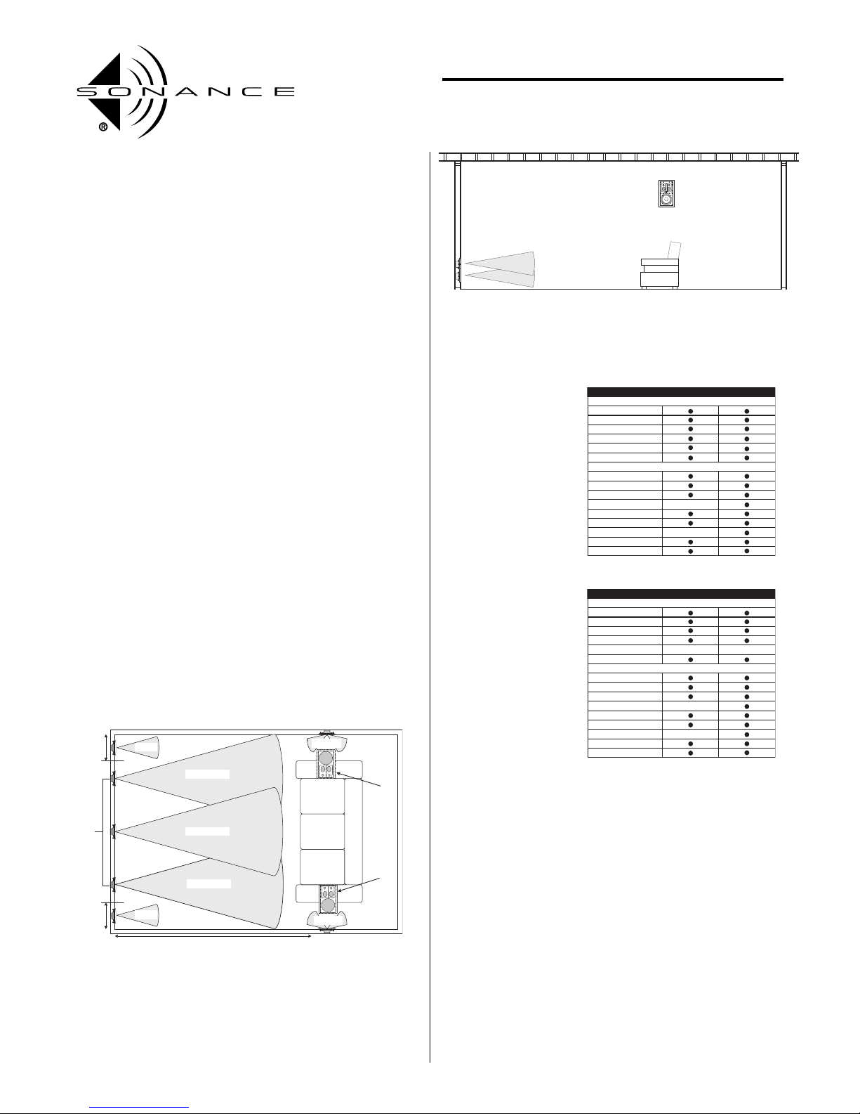
Locating your Cinema SUBs near a corner and close to the floor
(Diagrams 1 and 2) provides the neccessary acoustics to maximize efficiency and bass extension. The precise location of
your SUBs will be dictated by the space requirements of the
speakers, and in the case of the Cinema SUB, your decision
whether or not to employ the optional Cinema Back Box. The
Cinema SUB System requires a nominal 4" depth (2" x 4") stud
walls.Due to the high-energy output of which they are capable,
it is recommended that the Cinema SUBs be installed in the
optional Cinema Back Box available from your Sonance
installer.
The following gauge
quality speaker wire
is recommended for
the Cinema SUBs. •
14 gauge for less than
30 feet • 12 gauge for
between 30 and 75
feet • 10 gauge for
greater than 75 feet
Ve ri f y a d eq ua te pa r ts
and tools for the
installation:
INSTALLATION SAFETY
When installing Sonance Cinema speakers, basic safety precautions should always be followed to reduce the risk of fire,electric
shock,and injury to persons,including the following:
1. Never drill or cut into wall cavities that already contain electrical wiring or plumbing.
2. Follow all warnings and instructions in this manual and
marked on the product.
3. Do not install this product in a high humidity environment or
near water,for example a wet basement,wet bar, or swimming
pool.
4. Never touch the drivers or push objects of any kind into this
product through the grilles.
5. Always exercise caution when working in unfinished spaces
INSTALLATION INSTRUCTIONS
CINEMA SUB SYSTEM
PN.33-1599 12-03
1
Diagram 1
Diagram 2
18" min.
from side
wall.
6' to 10'
Range
18" min.
from side
wall.
Sub
Sub
10 feet from LCR speakers
THX Room Layout, top view.
Right
Center
Left
40" Ear from floor
Surround
Surround
Surround
speakers
may be
alternatively
mounted
in the
ceiling.
Twe e te r /
mid array
must face
front and
back of
room.
SONANC
E
PARTS LIST / TOOL LIST • CINEMA SUB
2 Cinema SUB speakers
2 Grilles
12 #8 x 3" mounting screws
2 Grille mounting rings
2 Back Boxes
8 Angle brackets
Electric Drill (1/4" - 3/8" drive)
1" Flat Bit
3/8" Bit
Stiff Wire (coathanger, fishtape)
Torpedo Level
Wire Strippers
Keyhole or Drywall Saw
Gloves
Pencil
PARTS LIST / TOOL LIST • CINEMA SUB
2 Cinema SUB speakers
2 Grilles
12 #8 x 3" mounting screws
2 Grille mounting rings
8 Angle brackets
Electric Drill (1/4" - 3/8" drive)
1" Flat Bit
3/8" Bit
Stiff Wire (coathanger, fishtape)
Torpedo Level
Wire Strippers
Keyhole or Drywall Saw
Gloves
Pencil
Installation without back box
NEW CONSTRUCTION RETROFIT
PAR TS
TOOLS
Installation with back box
NEW CONSTRUCTION RETROFIT
PAR TS
TOOLS
Page 2
2
such as attics. Areas with exposed joists present a significant
danger of injury from falls or stepping on nonstructural surfaces.Before working in areas with exposed joists,always create
temporary walkways using plywood or dimensional lumber.
CINEMA SUB WITH BACK BOX, NEW CONSTRUCTION –
BACK BOX INSTALLATION
Insert the Cinema SUB back box between studs, moving the
studs if necessary to achieve proper fit. Attach the back box
with the L brackets provided,or if back box is installed against
the floor plate, use long 2-1/2" screws through the studs into
the sides of the back box every 6". For optimum performance,
mount back boxes as low and near to a corner as possible.
Drill a hole as small as possible in the rear or side panel of the
back box and pass the speaker wire through it. For ease of
speaker installation, Leave two feet of extra wire beyond the
actual speaker mounting location. Seal the hole with silicone
caulking compound.
CINEMA SUB ACOUSTIC ENCLOSURE INSTALLATION
Speaker Placement – Survey sites for installation obstacles
such as plumbing,wiring, and other fixtures.Access the attic or
crawl space to check routing of air ducts and available mounting depth: Cinema Subs require 3-3/4" of wall depth and 2
cubic feet of volume.
At each selected site, use a stud locator to identify an open
space between studs.Drill a small hole in the center of the chosen area and insert a bent coat hanger to confirm that the cavity is clear.
Retrofit Hole – Using a level and draw a line around the cardboard cutout template to use as a pattern for cutting the hole.
Use a drywall saw to cut the hole,keeping the edges square and
paying particular attention to keeping the horizontal cuts level.
1. Remove Roto-Lock screws and toggle feet.
2. Remove six (6) Roto-Lock towers.
3. Using six (6) Roto-Lock screws,attach subwoofer to back box.
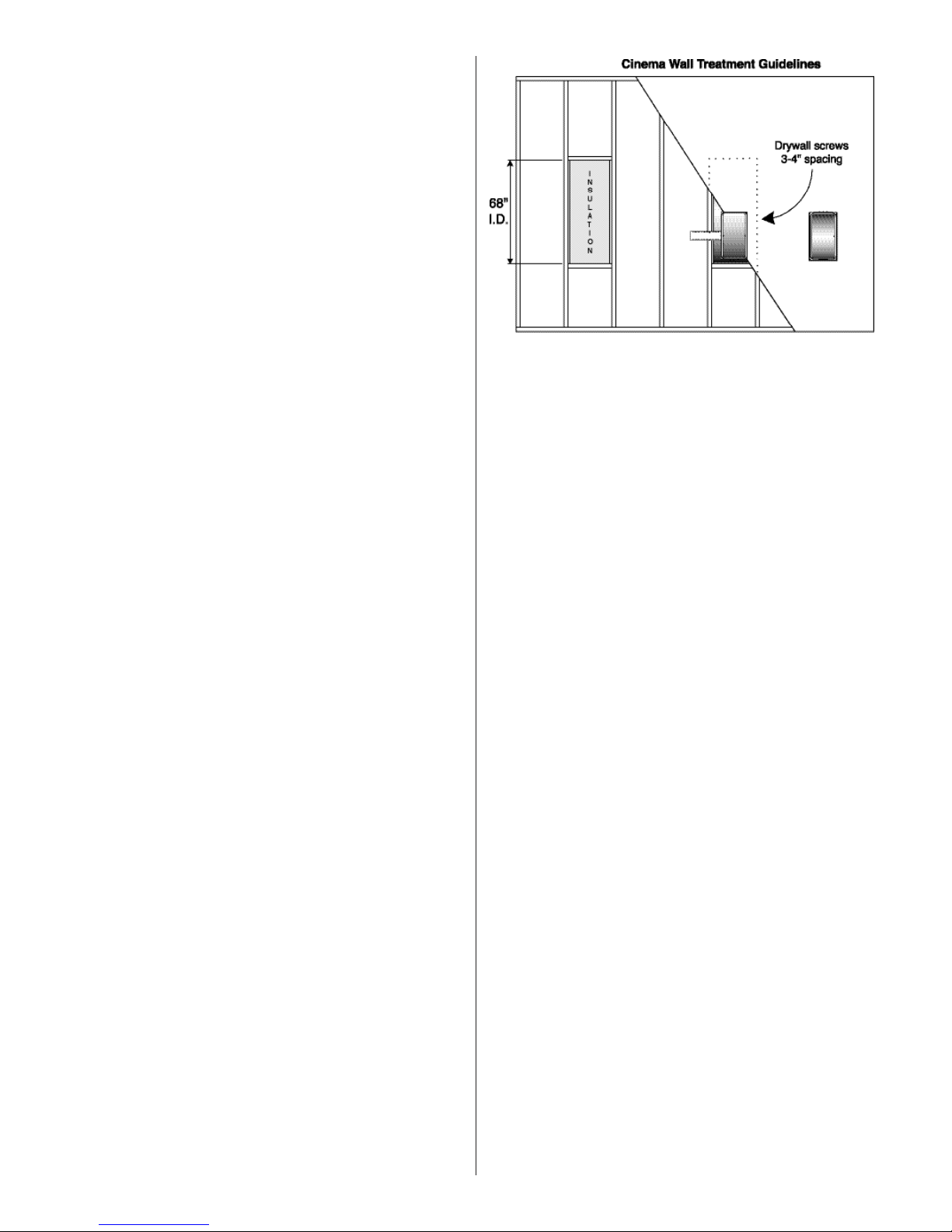
Insulation and Caulking – Silicone caulking compound should be
used to seal the junctions of fire stops,floor plate, and studs. The
stud bay should be as air tight as possible.Fill cavity with unfaced
fiberglass batting.
Secure drywall with screws every three to four inches in the
studs,fire stop(s) and floor plate that define the SUB enclosure.
Apply a bead of caulking compound to both the front and back of
studs around the perimeter of the enclosure. Reach through the
mounting ring to apply caulk.
Leave two feet of extra wire for ease of speaker installation.Attach
the wire to the bracket with a cable tie.
SPEAKER INSTALLATION
Wire Connections – Strip 1/2" of insulation from each speaker
wire.Attach the positive conductor to the red 5-way binding post
and the negative wire to the black post.To connect, loosen the nut
on the binding post until the hole in the post is visible.Insert the
stripped end of the wire through the hole, then snug the nut.Do
not over tighten.
Speaker Mounting –Screw each speaker assembly by inserting
the six screws provided through the baffle into the back box.
Replace the grilles.
CONNECTING THE CINEMA SUB AMPLIFIER
The Sonamp Cinema 260 specially is designed to drive subwoofers.
Connect the sub-woofer output interconnect to the left channel
input jack on the rear of the Cinema 260.If the source preamplifier
has no dedicated subwoofer output, use a pair of interconnect
cables from the preamp out to the left and right input jacks of the
Cinema 260.
If no line level output is available to drive the subwoofer, use a
Sonance OP-3 to convert high level speaker output to the
appropriate level for input to the Sonamp Cinema 260.Connect
subwoofer speaker wires to the right and left speaker terminals
on the back of the amplifier.
NOTES: Polarity of speaker wires is critical. All positive leads
(+) must be attached to red connectors throughout the system.
Since the Sonamp Cinema 260 subwoofer amplifier sends a
monaural signal to both speakers,either speaker (right or left)
may be driven by either amplifier channel.
The Sonamp Cinema 260 subwoofer amplifier is designed to
drive one speaker per pair of binding posts. Connecting additional speakers in parallel may cause damage to the speakers
and amplifier.
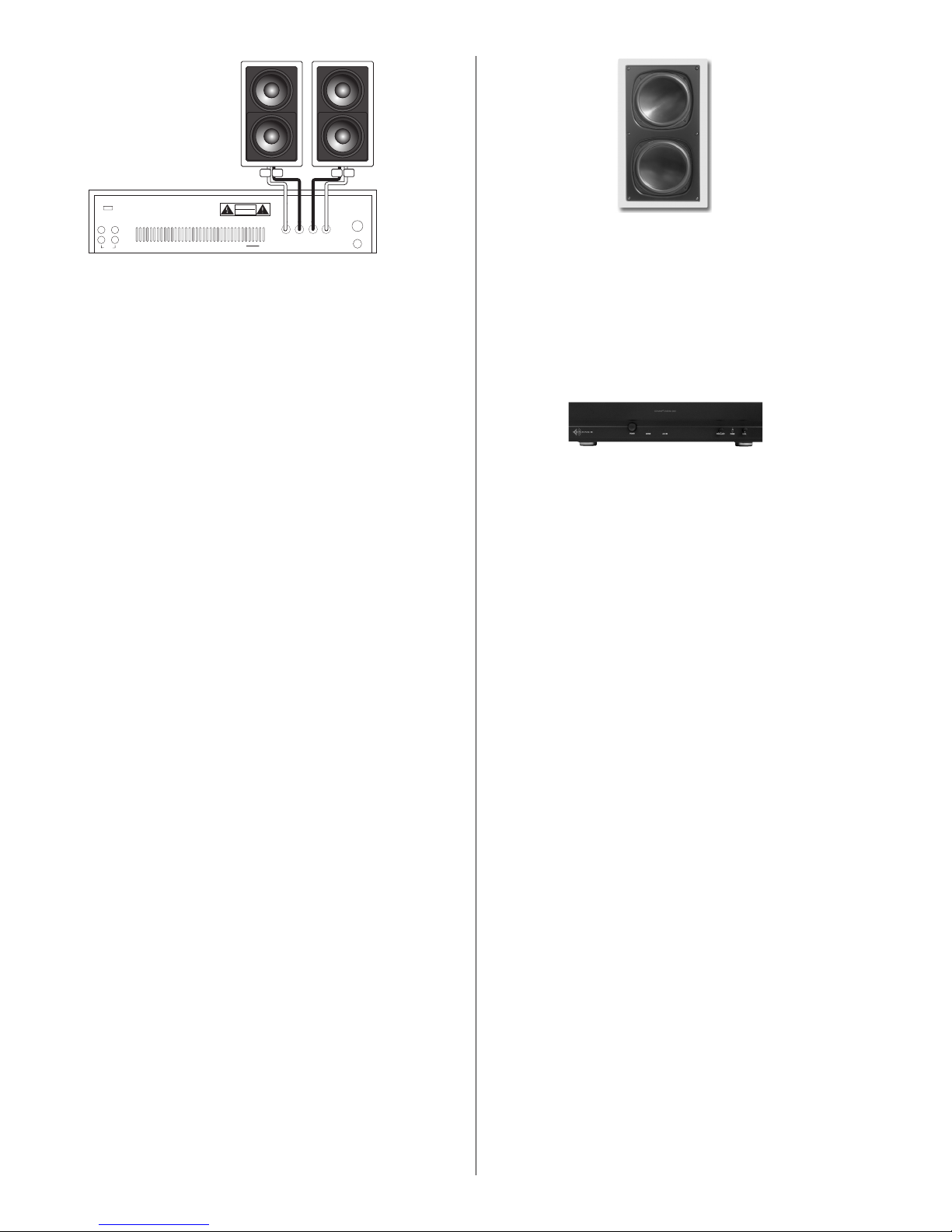
Do not tie amplifier output (+) terminals together and run a single 2 conductor to the two subwoofers. Each amplifier channel
requires separate positive (+) and negative (-) conductors,4 total
for each amplifier and two subwoofer modules.(See diagram 4)
Plug the power cord into an AC outlet of the voltage indicated on the
amplifier.Do not use a switched outlet on another component.
Diagram 3
Page 3
3
SUBWOOFER SETTINGS
Some experimentation will be necessary to achieve the best
possible integration of the Cinema SUBS with the other speakers in the system.Start with the following settings on the Sonamp
Cinema 260:
• FREQUENCY: fully clockwise,highest crossover frequency
• PHASE: down, 0,normal phase setting
• LEVEL: 12:00 (The 12:00 level setting is correct for most
Dolby AC-3 and THX processors.)
Always take SPL readings from ear level at the listening position.
When used in conjunction with some components, the bass
response of the Cinema SUBs will be greater with the phase
switch in the down position. Listen to music with significant
bass content with the switch in each position to determine the
correct setting for your system. Sitting in the normal listening
position, listen while a friend changes the phase switch position. The audibly louder setting is correct. Alternately, use an
SPL meter to determine which setting produces greater output
in the 75-125 Hz range.
If you experience buzzing or rattling during strong bass passages,it may be necessary to relocate or remove items in the listening room which become excited by the high energy levels
reproduced by your Cinema SUBs.
Diagram 4
In-Wall Infinite Baffle
Woofer –Two 8" (203mm) Polypropylene cone with a rubber surround
35Hz to 20,000 Hz ±3dB
4Ω nominal, 3Ω minimum
5 to 150 watts
90dB 1W/1m
Metal
11-1/2" x 20-1/4" x 3-7/8" (292mm x 514mm x 98mm)
Fixed Depth Bracket Cutout - 10-3/16" x 18-15/16" (259mm x 481mm)
Design
Driver Complement
Frequency Response
Impedance
Power Handling
Efficiency
Grilles
Speaker Dimensions
(WxHxD)
CINEMA SUB
125 watts per channel @2Ω
140 watts per channel @2Ω
.2% 250Hz @2Ω
56KΩ
500 watts (625VA) at full output
16-3/4" x 3-1/2" x 12-1/2" (425mm x 89mm x 318mm)
19" x 5-1/4" x 12-1/2" (483mm x 133mm x 318mm)
Optional Rack Mount Version
25 lbs (1.33 cubic feet)
SONAMP CINEMA 260
Power Output (RMS)
Both channels driven:
Dynamic Power at Clipping:
Total Harmonic Distortion:
Input Impedance:
Power Consumption:
Dimensions (WxHxD):
Shipping Weight
Use separate + and - conductors
HAZARDOUS ENERGY, MAKE PROPER SPEAKER
WARNING:
CONNECTIONS; SEE OWNERS MANUAL BEFORE USING
AUTO ON
DISCONNECT SUPPLY CORD BEFORE CHANGING FUSE
ATTENTION:
DEBRANCHER AVANT DE REMPLACER LE FUSIBLE
OFF ON
ATTENTION:
VOIR LE CAHIER D' INSTRUCTION
ATTENTION:
UTILISER UN FUSIBLE DE RECHANGE DE MEME TYPE
LINE
LINE
OUTIN
L
R
CAUTION:FOR CONTINUED PROTECTION AGAINST FIRE
47K
HAZARD USE ONLY SAME TYPE AND RATING FUSE.
for each sub module
AVIS:
CAUTION
RISK OF ELECTRIC SHOCK
DO NOT OPEN
RISQUE DE CHOC ELECTRIQUE-NE PAS OUVRIR
SONANCE
S/N
A DIVISION OF DANA INNOVATIONS
SAN CLEMENTE, CA 92672
SONAMP CINEMA 260
+
L
USE 8Ω SPEAKERS
Speaker
+-+ -
AC inlet is
AC FUSE
3AG 8A
+
R
--
120VAC/60Hz
750 VA
representative of
Sonamp Cinema 260
(230v version)
Page 4

TECHNICAL ASSISTANCE
If you any have questions about the operation or installation of
this device,please call our Technical Assistance Department on
any business day at:
(800) 582-0772 or (949) 492-7777; from 7 a.m. to 5 p.m.,PST.
OBTAINING SERVICE
If your product should need repair or service, contact your authorized Sonance dealer for help or use the following procedure:
1. Prior to calling, note the product’s model number,
serial number, purchase date, and original dealer’s name
and address.
2. Contact our Technical Assistance Department at the above
number(s) and describe the problem the unit is experiencing.
If applicable,they will issue a Return Authorization Number.
IMPORTANT: Do not return the unit to Sonance without first
obtaining a Return Authorization Number.
3. If you’re directed to return the unit to Sonance for repair,
pack the unit in its original shipping carton.If needed, you can
obtain replacement packaging from us for a small charge.Note:
it is best if you place it into an additonal outer “overcarton”
before shipment to minimize a chance of theft in shipment.
4. Contact United Parcel Service, Federal Express, or RPS
to arrange prepaid (not collect) shipping. Do not use the U.S.
Mail Service.
IMPORTANT: Freight collect shipments will be refused.
5.Write the Return Authorization Number on the outside of the
shipping carton. For warranty work, please include a copy of
the original bill of sale inside the package.
6. Ship the packaged unit to:
Returns Department
Sonance
212 Avenida Fabricante
San Clemente,CA 92672-7531
WARRANTY COVERAGE (U.S. ONLY)
If, within five (5) years from the date shown on the bill of sale,
the unit fails, due to a defect in workmanship or material,
Sonance will, at its option and at no charge, repair or replace
the components of such unit which prove to be defective. For
this warranty to be effective,the bill of sale must show that the
unit was purchased from an "Authorized Sonance Dealer" and
must list the price paid. This warranty shall apply exclusively
to the original purchaser and shall not apply to units purchased
for industrial or commercial use.
Furthermore,this warranty shall not apply if:
1) Damage to the unit was caused by accident,abuse,or misuse;
2) The unit was opened, modified,or repaired by unauthorized
personnel; or
3) The unit was not used as outlined in the operating instructions.
EXCLUSIONS AND LIMITATIONS
The warranty set forth above is in lieu of all other warranties,
express or implied, of merchantability, fitness for a particular
purpose, or otherwise. The warranty is limited to Sonance
products registered herein and specifically excludes any damage to loudspeakers and other allied or associated equipment
which may result for any reason from use with this product.
Sonance shall, in no event, be liable for incidental or consequential damages arising from any breach of this warranty or
otherwise. This warranty gives you specific legal rights, and
you may have other rights which vary from state to state.
Sonance • 212 Avenida Fabricante • San Clemente, CA 92672-7531, USA • (800)582-7777 or (714)492-7777 • FAX: (949) 361-5151 • Technical Support: (800) 582-0772
www.sonance.com
 Loading...