

SONA Electronics SM-SN-1, WSM-SN-1, WHM-SN-1, HM-SN-1 Installation And User Manual

1
Installation and User Guide
SM-SN-1 Mains Operated Smoke Alarm
WSM-SN-1 Mains Operated Smoke Alarm Wi-Safe 2
®
HM-SN-1 Mains Operated Heat Alarm
WHM-SN-1 Mains Operated Heat Alarm Wi-Safe 2
®
"sona install"
"sona learn in wireless"
2
W2 module contained within WSM-SN-1 and WHM-SN-1 independently tested to RF standard
ETSI EN 300 220-2 V2.3.2 (2010-02) by TRaC Global Ltd
0086
0086-CPR-557790
EN 14604:2005
DOP:SADOPSM-SN-01
BS EN 14604:2005
Licence No: KM557789
0086
0086-CPR-557790
EN 14604:2005
DOP:SADOPWSM-SN-01
BS EN 14604:2005
Licence No: KM557789
BS 5446-2: 2003
Licence No: KM607094
Sprue Safety Products Ltd. Vanguard Centre, Coventry CV4 7EZ UK
A Sprue Brand
GN3088R2
Email: technicalsupport@sonasafety.com / Web: www.sonasafety.com
Technical Support Line: 0800 171 2009
PLEASE READ THIS GUIDE IN FULL BEFORE USING YOUR ALARM!
This user guide is also available in large text and other formats.
Please call 0800 171 2009 for further information.
230 V AC 50 Hz mains powered smoke / heat alarm. Non replaceable 3 V battery backup. CLASS II
apparatus. The normal operating temperature range for this product is -10 °C to 45 °C. WARNING:
Wiring should be installed by a qualied electrician in accordance with BS7671. We advise you to
follow the new harmonized cable colour coding as specied in BS7671.
SM-SN-1
HM-SN-1 /
WHM-SN-1
WSM-SN-1
14 14

3
Introduction . . . . . . . . . . . . . . 4
Positioning . . . . . . . . . . . . . . 7
Hardwire Installation . . . . . . . . . 8
Hardwire Interconnect . . . . . . . . 10
Wireless Interlink . . . . . . . . . . . 11
Mixed Systems . . . . . . . . . . . . 13
INSTALLER GUIDE
Alarm Test . . . . . . . . . . . . . . . 14
Alarm Smart Silence
TM
. . . . . . . . 15
Sleep Easy
TM
. . . . . . . . . . . . . .15
Troubleshooting. . . . . . . . . . . .16
Be Prepared . . . . . . . . . . . . . . 18
Maintenance. . . . . . . . . . . . . .19
Disposal . . . . . . . . . . . . . . . . 19
Warranty . . . . . . . . . . . . . . . .20
USER GUIDE

4
INSTALLER GUIDE
INTRODUCTION
This user guide covers a number of different models. Some of the illustrations may look different to
your particular model.
DO:
• Leave this guide with the end user.
• Connect the alarm as late as possible in an installation, particularly in new builds,
to avoid contamination.
• Remove the dust cover before applying power.
• Ensure that after any building work or after repositioning large items of furniture (beds, sofas,
shelving units etc.), you carry out an alarm test on all alarms to ensure they are still working.
• Test your alarm weekly as well as testing any other interconnected alarms.
• Make sure your alarm is situated in one of the recommended locations only.
✓
Smoke Alarm
SM-SN-1 / WSM-SN-1
Heat Alarm
HM-SN-1 / WHM-SN-1

5
SMOKE ALARM SENSOR TECHNOLOGY
Thermoptek
®
technology combines the very latest in optical sensing with a thermal enhancement
providing a fast reaction to both fast aming and slow smouldering res in a single alarm. Thermoptek
technology constantly monitors for temperature change. If a rate of temperature rise is detected the
sensitivity of the smoke alarm is increased, providing a quicker response time to both re types.
HEAT ALARM SENSOR TECHNOLOGY
Thermistek™ technology incorporates a unique radiant heat dish (patent pending) to heighten
performance when exposed to a radiant heat source in real re situations. Constantly monitoring
for temperature change, if an increase in temperature is detected, the rate of rise is measured and if
predicted to exceed a pre-determined threshold will sound the alarm. This predictive quality provides
a quicker response time in rapidly increasing temperatures.
Heat alarms are designed for areas where dust and fumes may trigger frequent nuisance alarms in
conventional smoke alarms - ideal for attics, garages and kitchens. The HM-SN-1 / WHM-SN-1 are
xed point heat alarms using Thermistek sensing technology. All alarms are approved to class A1 and
will activate when the temperature reaches a preset range of 54 °C to 65 °C.
LITHIUM BATTERY TECHNOLOGY
All SONA mains powered smoke and heat alarms have a built in, sealed for life lithium battery (backup); designed to power the alarm in the event of a mains failure.
DO NOT:
• Expose this alarm to moisture, dripping, splashing, steam or condensation.
• Paint the alarm.
• Install heat alarms in escape routes instead of smoke alarms.
• Test your alarm with a naked ame. The test button tests the alarm’s full functionality.
• Ignore any alarm in the network if it is sounding, it is warning you of a potentially hazardous
situation.
×

6
SYSTEM GRADES AND CATEGORIES
The mains powered SONA™ alarms with 10 year life are suitable for Grade D systems. It is important
to determine the correct alarm system grade and category for the dwelling prior to installation.
A Grade D system is required for:
• New or materially altered dwellings, up to three storeys with no oor exceeding 200 m
2
.
• Existing dwellings with poor or inadequate re protection, up to three storeys with no oor
exceeding 200 m
2
.
• Individual dwelling units of two or more rooms in Houses in Multiple Occupation (HMOs) of one
or two-storeys, with no oor exceeding 200 m
2
.
There are three Levels of Detection (LD). Generally the greater the re risk the more comprehensive
the system should be.
LD1 = Maximum Protection. Alarms in all circulation spaces that form part of escape routes and all
areas where a re might start.
LD2 = Medium Protection. All circulation spaces and escape routes (e.g. hallways and landings) are
covered together with a provision of higher re risk areas (e.g. kitchen and living rooms).
LD3 = Minimum Protection. Alarms in all circulation spaces that form part of escape routes.
* Ensure that a Grade D system is adequate for the dwelling you are installing the alarms in.
7
DO:
• Install smoke alarms in circulation areas at a distance no greater than 7.5 m from the farthest
wall, no greater than 7.5 m from a door to any room in which a re might start and no greater
than 7.5 m from the next smoke alarm.
• Install heat alarms on the ceiling, ideally in the centre of the room.
• Install sufcient alarms to compensate for closed doors and obstacles.
• Install your Thermistek heat alarm at a distance no greater than 5.3 m from the farthest wall, no
greater than 5.3 m from a door to any room in which a re might start and no greater than 5.3 m
from the next heat or smoke alarm.
✓
POSITIONING
Locations of alarms must be compliant with either BS 5839: Part 6 or relevant Building Regulations if
in any doubt. This alarm is not intended for any non-residential, commercial or industrial application,
nor for any other purpose other than described in the above. For the best protection, heat alarms
should always be installed as part of a complete re protection system that includes smoke alarms.
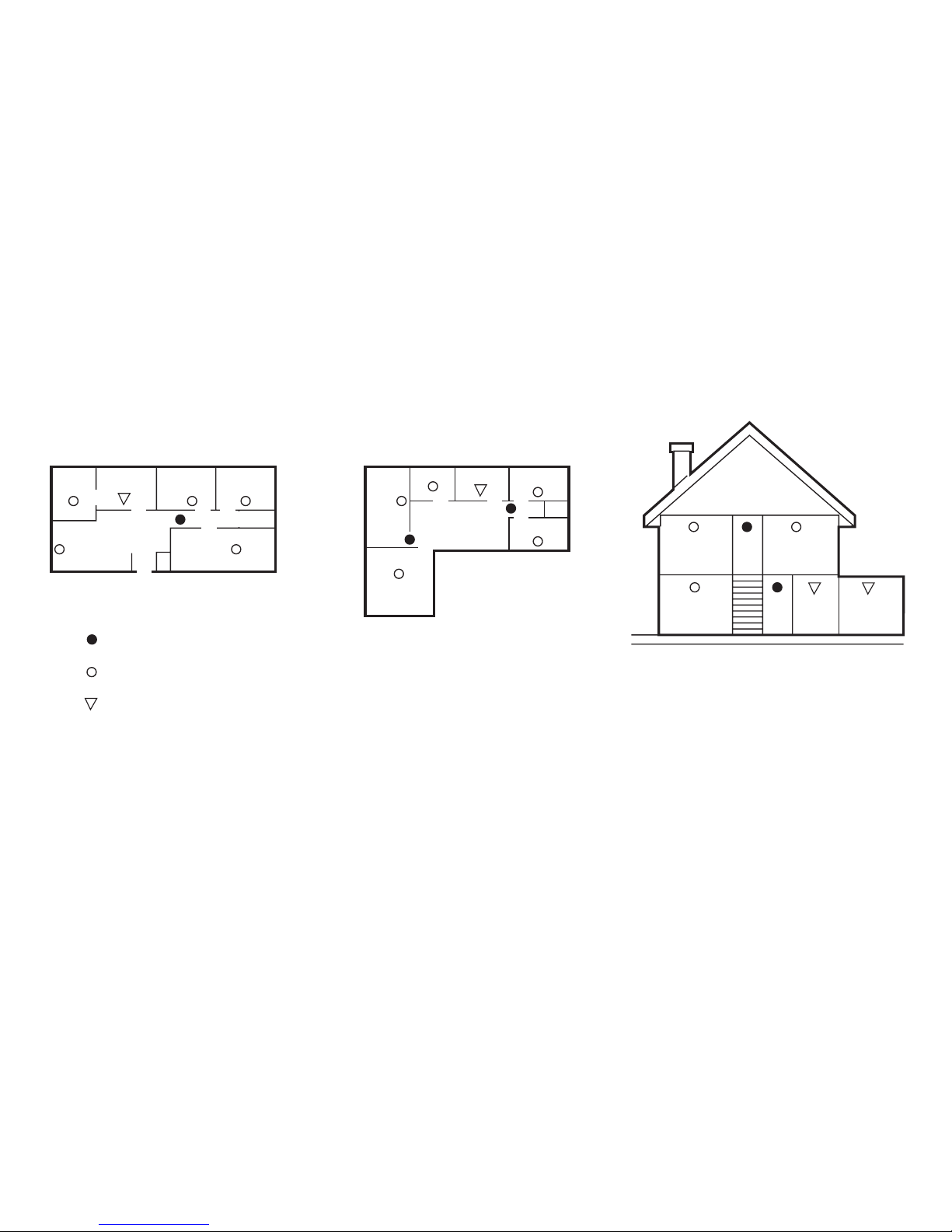
Smoke alarms for limited protection
Single storey,
one sleeping area
Single storey,
two sleeping area
Single storey,
dwelling
Additional smoke alarms for better coverage
Heat alarms
Dining
Room
TV
Room
Living
Room
Living
Room
Living
Room
Hall
Hall
Kitchen
Kitchen
Kitchen Garage
Bedroom
Dining
Room
Bedroom
Bedroom
Bedroom Bedroom
Bedroom
Bedroom
Bedroom

8
HARDWIRE INSTALLATION
The alarm base plate is designed to be permanently mounted, using its own built-in terminal block to
connect it to the mains. The base plate can be screwed directly to the ceiling.
• IMPORTANT: The circuit used to power the alarm must be a 24 hour voltage circuit that cannot
be turned off by a switch. BS 5839: Part 6 states that: For mains powered alarms, each with an
integral standby supply (Grade D), the mains electricity supply should take the form of either
a) an independent circuit at the dwelling’s main circuit board, in which case no other electrical
equipment should be connected to this circuit (other than a dedicated monitoring device installed
to indicate failure of the mains electricity supply to the alarms); or b) a separately electrically
protected, regularly used local lighting circuit.
• Ensure a permanent connection to the xed wiring of the building is made in a suitable
junction box.
• Remove the terminal block cover.
• If trunking is required, snap the break-out tab away from the base plate prior to connection.
• The wiring must be connected to the terminal block as follows:
Live (L) - Connect to the Live in the house wiring.
Neutral (N) - Connect to the Neutral in the house wiring.
Interconnect (I) - If desired, join the Interconnect wire between the alarms.
• Use the
terminal to safely terminate any copper Earth or green / yellow cable.
×
DO NOT:
• Install the alarms within 1500 mm (1.5 m) of a uorescent light tting and keep wiring at least
1000 mm (1 m) from these ttings.
• Install alarms on circuits containing uorescent light ttings or dimmer switches.
• Install alarms within 300 mm (12”) of light ttings or room corners.
• Install smoke alarms in wall positions that are less than 100 mm (4”) or more than 300 mm (12”)
away from the ceiling.
• Locate the Thermoptek smoke alarm close to bathrooms or showers as it can be susceptible to
nuisance alarms from steam.
• Install heat alarms on a wall.
 Loading...