

Page 1
SPECIFICATIONS
Type: Powered wireless subwoofer with DSP,
bass reflex cabinet. Can be used in wired set-up.
Amplifier: 200 W (digital Class D)
Woofer: 10” long throw
Frequency range: 30–100 Hz
Variable crossover frequency: 50–90 Hz
Dimension HxWxD: 390x620x150 mm
(without wall mounting bracket)
WIRELESS FEATURES
Built-in wireless receiver
Wireless full CD audio quality
No interference or delays
RF band (WIFI): 2.4 GHz
Sample rate: 48 KHz
Dedicated proprietary network protocol
Range: 20–100 m depending on conditions
Channel sniffing and frequency hopping
3 channels with 10 ID codes on each channel
Wired option with balanced in/outputs
CSW Subwoofer
User manual • Bruksanvisning • Manuel d’utilisation • Bedienungsanleitung • Manual del propietario
R
© Sonab Audio AB Sverige
Sonab® , Sonab logotypen, är registrerade varumärken av Sonab Audio AB, Sverige. System 9™. Alla rättigheter reserverade.
Sonab följer en policy om ständig produktutveckling. Specifikationer kan ändras utan föregående meddelande.
© Sonab Audio AB Sweden
Sonab® , the Sonab logotype are all registered trademarks of Sonab Audio AB, Sweden. System 9™. All rights reserved.
Sonab follows a policy of continuous advancement in development. Specifications may be changed without notice.
Page 2
This equipment has been tested and found to comply with the limits for a Class B digital device, pursuant to part 15 of the FCC
Rules. These limits are designed to provide reasonable protection against harmful interference in a residential installation. This
equipment generates uses and can radiate radio frequency energy and, if not installed and used in accordance with the instructions, may cause harmful interference to radio communications. However, there is no guarantee that interference will not occur in a
particular installation. If this equipment does cause harmful interference to radio or television reception, which can be determined
by turning the equipment off and on, the user is encouraged to try to correct the interference by one or more of the following
measures:
— Reorient or relocate the receiving antenna.
— Increase the separation between the equipment and receiver.
— Connect the equipment into an outlet on a circuit different from that to which the receiver is connected.
— Consult the dealer or an experienced radio/TV technician for help.
To satisfy FCC RF exposure requirements, a separation distance of 20 cm or more should be maintained between this device and
persons during device operation. To ensure compliance, operations at closer than this distance is not recommended. The antenna
used for this transmitter must not be co-located in conjunction with any other antenna or transmitter.
This device complies with Part 15 of the FCC Rules. Operation is subject to the following two conditions: (1) this device may
not cause harmful interference, and (2) this device must accept any interference received, including interference that may
cause undesired operation.
Pour satisfaire aux exigences de la FCC d’exposition aux radiofréquences, une distance de séparation de 20 cm ou plus doit être
maintenue entre cet appareil et des personnes lors de fonctionnement du dispositif. Pour assurer la conformité des opérations
au plus près que cette distance n’est pas recommandée. L’antenne utilisée pour ce transmetteur ne doit pas être co-localisés en
conjonction avec toute autre antenne ou transmetteur.
Cet appareil est conforme à la Partie 15 des règlements de la FCC. L’opération est soumise aux deux conditions suivantes: (1)
cet appareil ne peut causer d’interférences nuisibles, et (2) cet appareil doit accepter toute interférence reçue, y compris les
interférences qui peuvent provoquer un fonctionnement indésirable.
Under Industry Canada regulations, this radio transmitter may only operate using an antenna of a type and maximum (or lesser)
gain approved for the transmitter by Industry Canada. To reduce potential radio interference to other users, the antenna type and
its gain should be so chosen that the equivalent isotropically radiated power (e.i.r.p.) is not more than that necessary for successful communication.
Conformément à la réglementation d’Industrie Canada, le présent émetteur radio peut
fonctionner avec une antenne d’un type et d’un gain maximal (ou inférieur) approuvé pour l’émetteur par Industrie Canada. Dans
le but de réduire les risques de brouillage radioélectrique à l’intention des autres utilisateurs, il faut choisir le type d’antenne et
son gain de sorte que la puissance isotrope rayonnée équivalente (p.i.r.e.) ne dépasse pas l’intensité nécessaire à l’établissement
d’une communication satisfaisante.
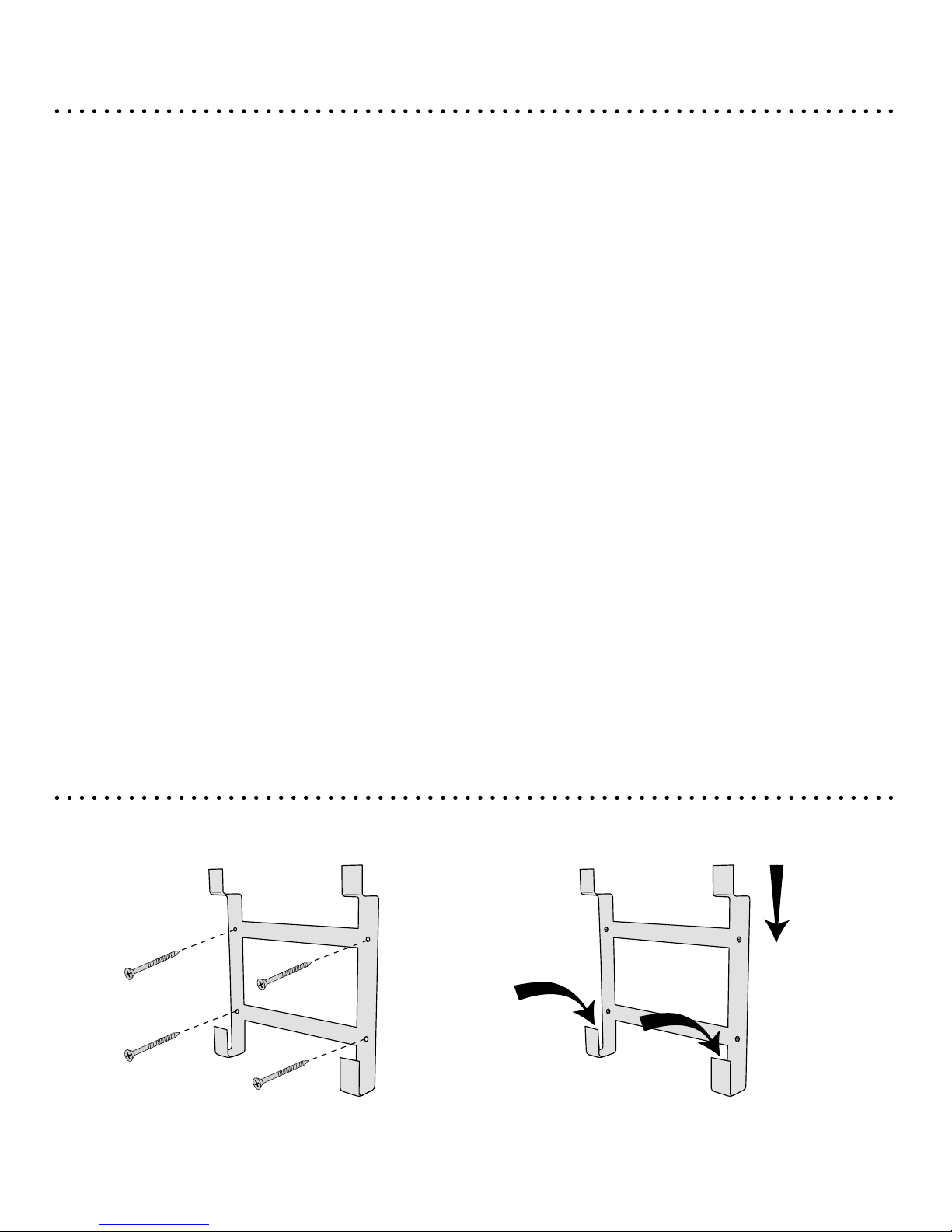
WIRELESS LOUDSPEAKER SONAB CLS
WALL BRACKET MOUNTING Use only supplied wall bracket.
Slide CSW into place on the fixturesMount bracket to wall.
Make sure to use suitable screws/plugs
depending on wall material
NOTE: Do all settings on rear before mounting CSW to its place
2
1
1
ENGLISH
Page 3
IMPORTANT SAFETY INSTRUCTIONS
1. Read these instructions.
2. Keep these instructions.
3. Heed all warnings.
4. Follow all instructions.
5. Do not use this apparatus near water.
6. Clean only with dry cloth.
7. Do not block any ventilation openings. Install in accordance
with the manufacturer’s instructions.
8. Do not install near any heat sources such as radiators, heat
registers, stoves, or other apparatus (including amplifiers) that
produce heat.
9. Protect the power cord from being walked on or pinched
particularly at plugs, convenience receptacles, and the point
where they exit from the apparatus.
10. Only use attachments/accessories specified by the manufacturer.
11. Unplug this apparatus during lightning storms or when
unused for long periods of time.
12. Refer all servicing to qualified service personnel. Servicing
is required when the apparatus has been damaged in any way,
such as power-supply cord or plug is damaged, liquid has been
spilled or objects have fallen into the apparatus, the apparatus
has been exposed to rain or moisture, does not operate normally, or has been dropped.
13. Damage Requiring Service
Unplug the apparatus from the wall outlet and refer servicing to
qualified service personnel under thee following conditions:
A. When the power-supply cord or plug is damaged,
B. If liquid has been spilled, or objects have fallen into the
apparatus,
C. If the apparatus has been exposed to rain or water,
D. If the apparatus does not operate normally by following the
operating instructions. Adjust only those controls that are
covered by the operating instructions as an improper adjustment of other controls may result in damage and will often
require extensive work by a qualified technician to restore the
apparatus to its normal operation,
E. If the apparatus has been dropped or damaged in any way,
and
F. When the apparatus exhibits a distinct change in performance this indicates a need for service.
14. Object and Liquid Entry
Never push objects of any kind into the apparatus through
openings as they may touch dangerous voltage points or
short-out parts that could result in a fire or electric shock. The
apparatus shall not be exposed to dripping or splashing and no
objects filled with liquids, such as vases shall be placed on the
apparatus. Don’t put candles or other burning objects on top
of this unit.
15. Batteries
Always consider the environmental issues and follow local
regulations when disposing of batteries.
16. The power supply and power cord for this apparatus is
intended for indoor use only.
WHERE THE MAINS PLUG OR AN APPLIANCE
COUPLER IS USED AS THE DISCONNECT DEVICE,
THE DISCONNECT DEVICE SHALL REMAIN READILY
OPERABLE.
WARNING:
TO REDUCE THE RISK OF FIRE OR ELECTRIC
SHOCK, DO NOT EXPOSE THIS APPARATUS TO
RAIN OR MOISTURE.
CAUTION:
TO REDUCE THE RISK OF ELECTRIC SHOCK,
DO NOT REMOVE COVER (OR BACK).
NO USER-SERVICEABLE PARTS INSIDE.
REFER SERVICING TO QUALIFIED
SERVICE PERSONNEL.
The lightning flash with arrowhead symbol, within an
equilateral triangle, is intended to alert the user to the
presence of uninsulated “dangerous voltage” within the
product’s enclosure that may be of sufficient magnitude
to constitute a risk of electric shock to persons.
The exclamation point within an equilateral triangle is
intended to alert the user to the presence of important
operating and maintenance (servicing) instructions in the
literature accompanying the appliance.
Page 4
OvErvIEw
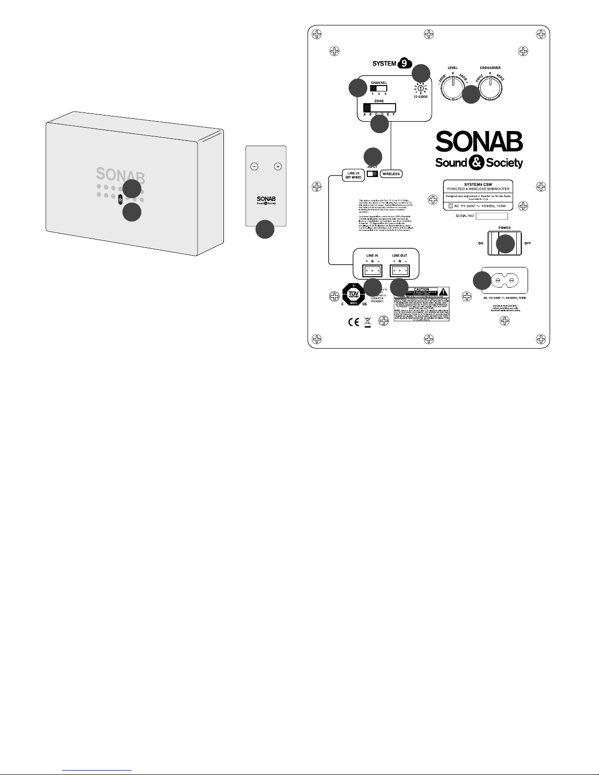
REAR
1. Power
Connect to AC outlet 115–230V.
2. Wireless – Line in Wired switch
Determines in which mode the speaker
should operate.
3. Crossover and Level controls
Set crossover frequency 50 Hz–90 Hz,
and level -20 dB to +20 dB.
4. Line Out
Connect to “Line in” on other System 9 speaker
with balanced cable.
5. Line In
Connect from “Line Out” on CGV or other
System 9 speaker with balanced cable.
(Make sure to switch to Line In Wired audio input,
see point 2.)
6. Volume Zone
Determines to which volume zone the speaker
should be set (A–F).
7. Channel
Set to channel 1, 2 or 3. (Whole system must
use same channel as CTX transmitter.)
8. ID code
On each Channel(1-2-3), there are 10 different
ID codes. Set whole system with same ID code.
9. Main power switch
FRONT
10. LED wireless indicator
Blue LED indicates that the speaker is receiving
signal (wired or wireless). If there is no signal the
speaker automatically goes into standby after 5
minutes and the LED changes from Blue to Red.
11. IR eye for remote control
12. Remote
Adjust bass levels -20dB to +20dB.
If manual volume knob on rear is used, this
overrides previous adjustments done by remote.
NOTE:
- Point 4–5 is only valid if the speaker is in wired mode.
- Point 6–8 is only valid if the speaker is in wireless
mode.
2
3
1
45
6
7
8
9
10
11
BASS LEVEL
12
 Loading...