


Installation, operating and
maintenance instructions
C0814 / C2028 / C2836 /C3650

1
INDEX
INTRODUCTION 2
Who should read these instructions 2
Symbols 2
Applicable standards 2
Important notes 2
USER GUIDE 3
Use of the boiler 3
Setting the burner to safety mode 3
DESCRIPTION 4
General description 4
Operating principle 4
Design characteristics 4
Boiler views and key to parts 4
TECHNICAL CHARACTERISTICS 5
General 5
Operating condition limits 5
Dimensions 5
Hot water output data 5
General characteristics 5
INSTALLATION 6
Boiler room 6
Chimney connections 6
Heating connection 7
Hot water connection 7
Electrical connections 8
COMMISSIONING 14
Filling the hot water and heating circuits 14
Using the boiler for the first time 14
MAINTENANCE 14
Recommendation 14
Boiler maintenance 14
Safety equipment maintenance 14
Draining the boiler 14
SPARE PARTS 15
Casings 15
Accessories 15
Electrical accessories 15
SERVICE RECORD 16
Details of the installation 16
Service engineer’s report 16
2
WHO SHOULD READ THESE INSTRUCTIONS
These instructions should be read by:
- the specifying engineer
- the installer
- the user
- the service engineer
SYMBOLS
The following symbols are used in these instructions:
APPLICABLE STANDARDS
The products described in this document have been certified at
European level (European Directive 92/42/EEC «Efficiency»). They
have also been awarded the Belgian “OPTIMAZ” LABEL (fuel oil
boiler).
IMPORTANT NOTES
These instructions are an integral part of the equipment to which
they relate and must be handed to the user.
The product must be installed and serviced by qualified engineers
in accordance with the regulations in force.
ES
declines all liability for any damage caused as a result of
incorrect installation or in the event of the use of appliances or
accessories that are not specified by ES.
Failure to follow the instructions describing the
test operations and procedures may cause injury to
persons or risks of environmental pollution.
N.B.:
ES reserves the right to change the technical characteristics and
specification of its products without notice.
INTRODUCTION
Important instructions for correct operation of the
installation.
D A N G E R
HOT
Danger of burning.
Danger of electrocution.
Essential instructions to ensure the safety of
persons and the environment.
ES : Energy Solutions

53%2'5)$%
53%/&4(% "/),%2
To ensure that your system operates correctly, please
have it serviced annually by a qualified engineer;
servicing should be completed before the start of the
heating season.
Starting the burner:
in normal operation the burner starts automatically if
the temperature of the boiler is below the set point.
Before carrying out any work on the boiler, isolate it
from the electrical supply at the switch on the external
control box.
Also place the main switch on the control panel to
“OFF”.
9OUSHOULDFAMILIARISEYOURSELFWITHTHECONTROLPANEL
FIG
The user must not attempt to gain access to the
components inside the control panel.
1. Control thermostat
When the boiler is used for heating only, the boiler temperature may
be set at 60 to 90°C. If the boiler is used to generate domestic hot
water and heating, the boiler’s control thermostat should be set at
80°C to ensure optimum operating conditions.
2. Main switch
Use this switch to turn the boiler on and off.
3. Summer/Winter switch
Use this switch to star t and stop the heating pump.
4. Thermostat-pressure gauge
This gauge shows the temperature of the boiler and the pressure in
the primary heating circuit. The temperature must not exceed 90°C.
If it rises above this point, turn off the boiler and check the settings
on the thermostat. If the problem persists, call a technician.
The pressure must not fall below 1 bar. If it does fall below this point,
look up the section entitled “Gauge pressure of the heating installation”
in this section below.
5. Manual reset high-limit thermostat
If the boiler temperature exceeds 103°C, this safety device will be
enabled. The boiler temperature must drop below 60°C to re-start.
Unscrew the cover and press the re-start key with a pen or an object
with a similar sharp point. Replace the cover. If the fault persists,
turn off the boiler and call a technician.
0UMPOPERATION
The pump is controlled by a reset high limit thermostat, which is
located at the rear of the boiler. This is pre-set at 45°C. When the
boiler starts up, it delays the activation of the boiler pump, thereby
preventing any risk of corrosion in the combustion chamber.
'AUGEPRESSUREOFTHEHEATINGSYSTEM
Your system must be fitted with a heating safety valve calibrated to
3 bars.
Ensure that the system is always under water pressure. When the
system is cold and the air inside it has been vented, the gauge
must indicate a pressure between 0.5 and 1.5 bar depending on
the height of the building.
4OADDWATERREFERTO&IGON0AGE
• Open the filling valve (5).
• Close the valve properly after filling.
• Vent the system in order to obtain an accurate reading of the
pressure inside the heating circuit.
3AFETYVALVES HEATINGCIRCUIT
If water is found to be escaping from one of the safety valves, stop
the boiler and contact your installer for advice.
A monthly test is recommended:
Lift the lever on the drain cock for a few seconds to ensure that the
safety valve is working correctly.
If there is a problem after this short test, please
contact your installer for advice.
The water escaping from the safety valve can
be extremely hot and cause serious burns.
D A NG E R
HOT
FIG#ONTROLPANEL
FIG0814 #ONTROLPANEL
2 5133
"52.%23(54$/7.
If the burner is not working:
1. The burner indicator lamp lights up.
2. Press the burner reset button &IG on the burner. Turn the
boiler off for several seconds at the main switch, then restart the
boiler.
3. If the burner still does not work, rearm the manual reset highlimit
thermostat on the control panel &IG.
4. If the anomaly persists, please contact your installer.
FIG
FIG
²#
3 1

4
DESCRIPTION
GENERAL DESCRIPTION
• Model is a single boiler (heating).
• Equipment required: a water connection kit for the heating circuit
supply (optional).
• The 0814 control panel includes a control thermostat and a
thermostat pressure gauge.
• The control panel on 2028 boilers includes a main switch,
a Summer/Winter switch, a thermostat pressure gauge, a control
thermostat and a manual reset high-limit thermostat.
• 0814 Model: output of 16.6 kW.
• 2028 Model: Outputs in the range 20 to 25 kW.
• 2836 Model: Outputs in the range 28 to 36 kW.
• 3650 Model: Outputs in the range 36.5 to 51 kW.
OPERATING PRINCIPLE
Simple to control, safety assured
The temperature of the water in both the heating circuit and the hot
water circuit is regulated by a single control. This is achieved by
means of the control thermostat and the bulb is located beside the
boiler outlet. switch.
• A manual reset high-limit thermostat locks the burner if the
primary water temperature reaches 103°C.
• A minimum thermostat, fitted at the rear of the boiler, and preset
at 45°C, delays the activation of the boiler pump. This prevents
any risk of corrosion in the combustion chamber.
DESIGN CHARACTERISTICS
Outer body
The outer body which holds the primary water is made from STW 22
heavy gauge steel.
Flue ways
The boiler’s flue ways can be accessed from the front and include
a set of removable turbulators, in either stainless steel or chrome,
which have been specially designed to provide the optimum
combustion efficiency.
Combustion chamber
The boiler features a large, water-cooled combustion chamber to
guarantee a good flame.
Removable burner chamber plate
The chamber plate is fitted on a hinge (left or right) and made from
STW 22 steel. It is protected from the flame by a ceramic fibre
padding and a vermiculite brick.
Insulation
The burner body is insulated with rock wool padding (50mm thick).
Casing
The boiler is covered with a steel casing that has been stove enamelled
at 220°C after scouring and phosphating.
BOILER VIEWS AND KEY TO PARTS
1. Top cover
2. Heating outlet
3. Heating return
4. Chimney connection
5. Heating circuit
6. Combustion chamber
7. Boiler drain cock
8. Fuel oil burner
9. Left-right removable burner chamber plate
10. Exchanger (flue ways)
11. Front panel
12. Control panel
1 2
756
3
12
10
9
11
8
4
fig. 5

5
TECHNICAL CHARACTERISTICS
GENERAL
The appliances are supplied fully assembled, tested and packed
standing on a timber base with impact protection strips and wrapped
in
heat-shrunk plastic film. When the appliance arrives, remove the
pac
kaging and check that no parts have been damaged in transit.
Ref
er to the dimensions and weights listed below for handling
pur
poses:
DIMENSIONS
OPERATING CONDITION LIMITS
Maximum service pressure (tank filled with water)
- Heating circuit: 3 bar
- Domestic hot water circuit : 10 bar (*)
Test pressure
(tank filled with water)
- Heating circuit: 4,5 bar
- Domestic hot water circuit : 13 bar (*)
Operating temperature
- Maximum temperature: 90°C
(*) if the boiler is connected to a domestic hot water production tank.
GENERAL CHARACTERISTICS 0814 2028 2836 3650
Input
kW
18.4 22.0 / 28.0 30.4 / 40.0 40.0 / 57.0
Output
kW
16.6 20.0 / 25.0 27.0 / 35.7 36.5 / 51.0
Pressure loss of the flue gas circuit
mbar
0.11 0.15 0.17 0.15
Heating circuit capacity
L
17 31 37 53
Heating connection (female)
Ø
3/4” 1” 1” 1” 1/4
A mm B mm C mm D Ø mm E mm F mm G mm Kg (*)
0814
370 565 495 80 425 357 187 62
2028
470 700 566 130 550 445 260 108
2836
470 765 566 130 615 510 260 122
3650
530 805 656 150 645 550 260 157
(*)
The weights shown are the drained weights.
A
G
B
E
Ø
D
C
F

BOILER ROOM
Important
• Never obstruct the ventilation.
• Do not store inflammable products in the boiler room.
• Avoid storing corrosive products such as paint, solvents, chlorine,
salt, soap or other cleaning products near the boiler.
Accessibility
The boiler room should be big enough to allow easy access to the
boiler. Minimum clearances around the boiler (mm):
- to the front 500
- to the rear 150
- to the sides 100
- above 700
Ventilation
The boiler room must have both low- and high-level ventilation
(see fig. 6).
For your information, the table below gives the minimum
ventilation requirements according to Belgian regulations.
The user must ensure that his boiler room ventilation complies
with local regulations.
A. High-level ventilation
B. Low-level ventilation
C. Draught stabiliser
D. Clea n ou t do or
E.
Height of lined chimney
F. Chimney diameter
A
B
D
F
E
C
Base
The base on which the boiler will be mounted must be made from
noncombustible materials.
CHIMNEY CONNECTIONS
IMPORTANT
The boiler must be installed by a qualified engineer
in accordance with the local standards and codes of
practice.
The diameter of the chimney must not be less than the
diameter of the boiler’s chimney reducer.
A chimney connector is required.
fig. 6 : Boiler ventilation
Important note:
The above table is shown by way of indication only as
regulations vary from country to country.
The high output of our boilers means that the flue
gases are at a low temperature.
The attendant risk of condensation may cause damage
to
some chimneys. To avoid this risk we strongly advise
tha
t you line the chimney.
Pl
ease contact your installer for any further information.
Chimney 0814 2028 2836 3650
E = 5 m Ø min. F mm 97 130 143 170
E = 10 m Ø min. F mm 82 130 130 143
E = 15 m Ø min. F mm 80 130 130 130
6
INSTALLATION
Ventilation 0814 2028 2836 3650
Fresh air supply min.
m
3
/h
33 50 72 102
High-level ventilation (A)
dm
2
150 150 150 150
Low-level ventilation (B)
dm
2
150 150 150 170

7
INSTALLATION
ES water kit
ES can supply an optional
pre-assembled water kit.
This kit comprises:
• A pump;
• A 3-way manual valve. This
valve can be power-operated if
required;
• Connection pipes that can be
used to connect a second
heating circuit;
• Two isolating valves;
• Connectors for the right- or
efthand mounting of the
expansion vessel, the safety
valve with pressure gauge and
the fill valve.
The expansion vessel is not
included.
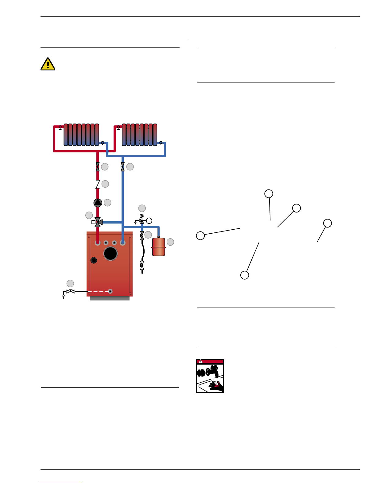
Typical single-circuit connection
Drain
The drain cock and safety valve must be connected to the building
drain.
fig. 10 : Heating system connection
9
5
6
2
1
3
8 8
4
CONNECTING THE HEATING SYSTEM
1. 3-way power-operated mixer valve
2. Safety valve calibrated to 3 bar, with pressure gauge
3. Pump
4. Non-return valve
5. System filling valve
6. Expansion vessel
8. Heating system isolating valve
9. Drain cock
fig. 9 : ES water kit
ES : Energy Solutions

8
INSTALLATION
Optional accessories
Safety group Ø 3/4”
Pressure reducing valve Ø 3/4“
Thermostatic mixer Ø 3/4”
Expansion vessel 5 litres
ELECTRICAL CONNECTIONS
Power supply principle
The boiler operates on a single-phase supply of 230 V/50 Hz.
You should install a control box with main switch and 6A fuses
externally to the boiler to allow the boiler to be isolated from the supply
for servicing and repairs.
Statutory compliance
The installation must comply with your local standards and codes of
practice.
Safety
The stainless steel if present water tank must be provided with a
separate earth.
The boiler must be isolated from the electrical supply
before any work is carried out on it.
Electrical wiring of boilers
1. Main switch
2. Summer/Winter switch Thermal reset high-limit thermostat (95°C)
3. Control thermostat (60/90°C)
4. Manual reset high-limit thermostat (103°C max.)
5. Minimum thermostat 45°C (T.O.D)
6. Pump (optional)
7. Room thermostat
Wiring diagram key
B. Blue
Bk. Black
Br. Brown
G. Grey
Or. Orange
R. Red
W. White
Y/Gr. Yellow/Green
230V-50 Hz
6A
1 2
C
1 2
C
Br
B
B
R
Y/Gr
Br
Y/Gr
Bk
Or
W
G
B
Br
Y/Gr
B
R
R
B
G
1
2
5
4
3
6
7
W
Or
Or
Bk
Y/Gr
2028
2836
3650
230V-50 Hz
T1
T2
T1
T2
1 2
C
1 2
C
t
t
M
0814
4
5
3
6
G
G
R Or Or
B
Bk Br
Br
Bk
B B
B

L1 N CH HW
Central
heating
pump
2028, 2837 and 3650
From S3 and B4 of terminal block
0814
Circulation pump supply
Tank
stat
Room
stat
Hot
water
pump
INSTALLATION
9
WIRING FOR MULTI PUMP CONFIGURATION

INSTALLATION
MAINTENANCECOMMISSIONING
2. Vent the system.
3. Once you have vented the system, return the pressure to the
static pressure plus 0.5 bar.
Height of the heating system:
• 10 m ➠ heating circuit pressure = 1.5 bar
• 15 m ➠ heating circuit pressure = 2 bar
USING THE BOILER FOR THE FIRST TIME
1. Check the fuel oil supply connection and ensure that it is free
from leaks.
2. Check the electrical connection to the boiler and the boiler room
ventilation, and ensure that the flue gas discharge pipes and the
burner chamber plate are properly gas tight.
3. Set the boiler thermostat to between 60° and 90°C.
4. Place the Summer/Winter switch to the required position.
5. Place the main switch to “ON”.
6. Carry out the necessary venting operations, measurements and
settings.
RECOMMENDATION
It is compulsory to have the boiler serviced once a year. Boiler
servicing and checking must be carried out by a qualified engineer.
MAINTAINING THE BOILER
1. Isolate the boiler from the electrical supply at the switch on the
external control box and close the fuel oil supply valve.
2. Place the main switch on the control panel to “OFF”
(except for the
0814).
3. Remove the boiler front panel (1) (except for the 0814).
4. Loosen the two nuts or locking clamps for the 0814 to open the
burner chamber plate (2).
5.
Remove the insulating brick
(for the 0814 only).
6. Remove the stainless-steel turbulators (3).
7. Brush the flue ways, clean the chamber and vacuum up any soot
dep
osits.
8. Check the insulation of the burner chamber plate (4).
9. Before reassembling, clean the burner combustion head (5).
10. Check that the thermostats and safety valves are working
correctly.
14
MAINTENANCE OF SAFETY EQUIPMENT
- Check that all thermostats and safety devicesoperate correctly: the
boiler thermostat and the manual reset high-limit thermostat (103°C).
-
Check the heating circuit safety valves.
DRAINING THE BOILER
The water draining from the drain cock is
very hot and can cause serious burns.
Keep all persons away from running
hot water.
Draining the heating circuit (fig. 20)
1. Place the main switch on the control panel to “OFF”, isolate the
boiler from the electrical power supply at the switch in the external
con
trol box.
2. Close the isolating valves (8) in the heating circuit.
3.
Connect a flexible tube to the drain cock (9).
4.
Open the drain cock (9) to drain the heating circuit.
D A NG E R
HOT
FILLING THE HEATING CIRCUIT
IMPORTANT
If your boiler is connected to an ES tank, it is
ES : Energy Solutions
essential to fill the domestic water circuit before the
heating circuit.
1. Open valves 5 and 8 to fill the heating circuit and make sure the
pressure does not exceed 2 bars.
9
5
6
2
1
3
8 8
4
fig. 20
fig. 21
1
2
3
5
4

15
SPARE PARTS
N° CASINGS
0814 2028 2836 3650
A01 Right side 21471387 21471380 21471381 21471382
A02 Left side 21472387 21472380 21472381 21472382
A03 Front panel - 21473380 21473381 21473382
A04 Rear panel 21474387 21474380 21474381 21474382
A05 Top cover 21475387 21475380 21475380 21475382
A06 Unequipped control panel 21477387 21477380 21477380 21477382
A07 Front bridge 21473387 - - -
N° ACCESSORIES
B01 Unequipped body 30465160 30465153 30465154 30465155
B02 Burner chamber plate 2147P371 2147P380 2147P381 2147P382
B03 brick backplate - 2147E380 2147E381 2147E382
B04 Burner chamber plate insulating brick 51701000 51404028 51404029 51404030
B05 Door ceramic fibre insulating cord - 51401113 51401113 51401113
B06 Burner chamber insulating cover - 51401127 51401128 51401129
B07 Pressure gauge thermometer 54763009 54441008 54441008 54441008
B08 Drain cock, Ø 1/2” 55426001 55426001 55426001
B09 M 10 19x33mm hinge pin - 47405252 47405252 47405252
B10 Probe attachment spring 47438008 47438008 47438008 47438008
B11 Turbulators 50423098 50423097 50423097 50423098
B12 H.D.P.E. handle - 49410280 49410280 49410280
B13 Flame inspection window 50423008 50423008 50423008 50423008
B14 Grommet 54428001 54428001 54428001 54428001
B15 Brass pocket, Ø 1/2” / L. 100 mm 63438001 63438001 63438001 63438001
B16
Control panel self-adhesive - 617G0050 617G0050 617G0050
B17 Burner chamber plate insulation 51700033 - - -
B18 Door locking clamp 47405137 - - -
B19 Male/female brass chimney reducer, Ø 1/2” x 1/4” 43416065 43416065 43416065 43416065
B20 Clip retainer 47405004 47405004 47405004 47405004
B21 Stud 47405005 47405005 47405005 47405005
N° ELECTRICAL ACCESSORIES
C01 Full control panel - 24614108 24614108 24614109
C02 ON/OFF switch - 54428116 54428116 54428116
C03 Summer/Winter switch - 54428107 54428107 54428107
C04 90°C control thermostat 54442045 54442045 54442045 54442045
C05 Manual reset high-limit thermostat (103°C) 54442015 54764009 54764009 54764009
C06 Thermal reset high-limit thermostat (45°C) 54442027 54442027 54442027 54442027
C07 Wiring 25435217 - - -

16
SERVICE RECORD
Installation date:
% CO2 (max. load) :
Flue gas T°:
Efficiency:
Fuel oil pressure:
Model:
Serial number:
Heating system pressure setting:
Name and signature:
DETAILS OF THE INSTALLATION
Installation date:
% CO2 (max. load) :
Flue gas T°:
Efficiency:
Fuel oil pressure:
Comments:
Name and signature:
SERVICE NOTES
Installation date:
% CO2 (max. load) :
Flue gas T°:
Efficiency:
Fuel oil pressure:
Comments:
Name and signature:
Installation date:
% CO2 (max. load) :
Flue gas T°:
Efficiency:
Fuel oil pressure:
Comments:
Name and signature:
Installation date:
% CO2 (max. load) :
Flue gas T°:
Efficiency:
Fuel oil pressure:
Comments:
Name and signature:
Installation date:
% CO2 (max. load) :
Flue gas T°:
Efficiency:
Fuel oil pressure:
Comments:
Name and signature:
 Loading...