

Page 1

Seite 1 von 13
User Manual
DVM-HDBT-EX2
HD-BaseT-Extender
HDMI+2xIR+RS232 70m
Page 2
Seite 2 von 13
NOTICE: Please read this user manual carefully before using this product.
Pictures shown on this manual are for reference only, different model and
specifications are subject to real product.
Update History
Version
Date
Update Content
1.0
2013.05.29
First version.
1.1 2013.11.29
Changed
product design
1.2
2014.04.16
Modified package cont ent s.
1.3 2014.04.28
Removed the built
-in IR receiver and added collocation
products.
This manual is for operation instruction only, not for any maintenance usage. The
functions described in this version are updated till April 2014. Any changes of
functions and parameters since then will be informed separately. Please refer to
the dealers for the latest details.
All product function is valid till 2014-04-28.
Page 3

Seite 3 von 13
Table of Contents
1. Introduction ................................................................................................................. 4
1.1 Introduction ....................................................................................................... 4
1.2 Features ............................................................................................................ 4
1.3 Package Contents ............................................................................................. 4
2. Introduction of Product Appearance ........................................................................... 5
2.1 Transmitter .................................................. Fehler! Textmarke nicht definiert.
2.2 Receiver ...................................................... Fehler! Textmarke nicht definiert.
3. System Connection .................................................................................................... 7
3.1 Usage Precautions ............................................................................................ 7
3.2 System Diagram ................................................................................................ 7
3.3 Connection Procedure ....................................................................................... 7
3.4 Application ......................................................................................................... 8
3.5 Twisted Pair Cable Connection.................... Fehler! Textmarke nicht definiert.
3.6 Collocation Products.......................................................................................... 8
4. Specification ............................................................................................................. 10
5. Troubleshooting & Maintenance ............................................................................... 11
Page 4

Seite 4 von 13
1. Introduction
1.1 Introduction
This is an HDMI/IR/RS232 twisted pair including transmitter and receiver. The Extender
uses HDBaseT technology to deliver HDMI signal, max transmission distance up to 60
meters with CAT5e/CAT6 cable. CEC, bi-directional RS232&IR control, and POE are
supported.
1.2 Features
Support Full HD: Delivers high resolution image (1080p@60Hz@48
b/pixels/3D/4Kx2K).
Max transmission distance is up to 60 meters over single CAT5e/CAT6 cable.
High Bandwidth: 10.2Gps.
HDTV Compatible, use HDMI 1.4 and HDCP compliant.
Support PoC & CEC.
Connect with a displayer to transmit EDID and HPD signals constantly by using a
CAT5e cable.
Use HDBaseT technology.
Bi-directional RS232/IR control.
LED indicators show work status.
Wall/table-mountable aluminium enclosure, PT case design.
Note: Please use a CAT5e cable with low impedance (Shielded twisted pair will be better
and should be well grounded
) for good transmission effect.
1.3 Package Contents
1 x Transmitter
1 x Receiver
4 x Mounting ears
8 x Plastic cushions
2 x RS232 cables
8 x Screws
1 x Power adapter (DC 24VÉ1.25A)
1 x User manual
Notes: Please confirm if the product and the accessories are all included, if not, please
contact with the dealers.
Page 5
Seite 5 von 13
2. Introduction of Product Appearance
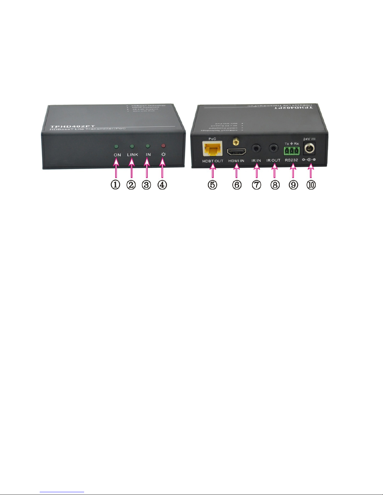
2.1 Transmitter
1) ON: Working status indicator of this device. When the device works fine, this green
LED will keep blinking. And it will get off when the device stops work.
2) LINK: Twisted Pair Link status indi cato r, green LE D. It will keep on when connection
is successful.
3) IN: When connected with devices support HDCP and work normally this LED will
keep on. If devices not support HDCP, this green LED will blink.
4) POWER LED: LED indicator of power. When connect with power, red LED will keep
on.
5) HDBT OUT: Connect to the HD BT IN port of Receiver with a CAT5e cable.
6) HDMI IN: Connect to HDMI source.
7) IR IN: Connect with IR receiver, the IR signal received from this port can only send
out in TPHD402PR.
8) IR OUT: Connect with IR sender, the sending IR signal are received from
TPHD402PR.
9) RS232: RS232 connector.
10) 24V DC: Connect with power supply (Not necessary if Receiver c onnects with
power).
Note:
Pictures shown on this manual are for reference only, different model and
specifications are subject to real product.
Page 6
Seite 6 von 13
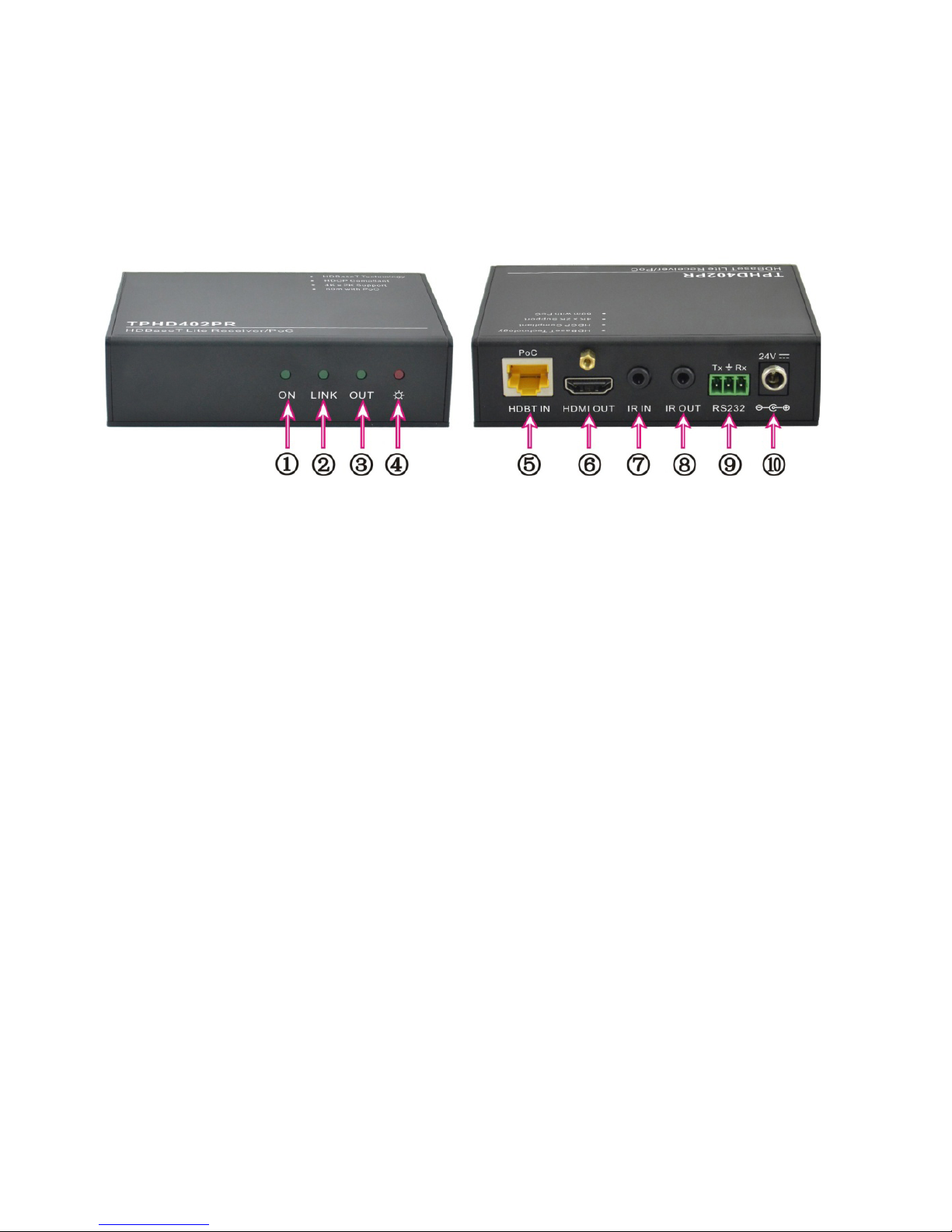
2.2 Receiver
1) ON: Working status indicator of this device. When the device works fine, this green
LED will keep blinking. And it will get off when the device stops work.
2) LINK: Twisted Pair Link stat us indicator , green LE D. It will keep on when connection
is successful.
3) OUT: W hen connected with devices support HDCP and work normally this LED will
keep on. If devices not support HDCP, this green LED will blink.
4) POWER LED: When connect with power, red LED will keep on.
5) HDBT IN: Connect to the HDBT OUT port of Transmitter with a CAT5e cable.
6) HDMI IN: Connect to HDMI display device.
7) IR IN: Connect with IR receiver, the IR signal received from this port can only send
out in Transmitter.
8) IR OUT: Connect with IR emitter, the sending IR sig nal are re ceived fr om Transmitte r.
9) RS232: RS232 connector.
10) 24V DC: Connect with power supply (Not necessary if Transmitter connects with
power).
Note:
Pictures shown on this manual are for reference only, different model and
specifications are subject to real product.
Page 7
Seite 7 von 13
3. System Connection
3.1 Usage Precaution s
1) System should be installed in a clean environment and has a prop temperat ure and
humidity.
2) All of the power switches, plugs, sockets and power cords should be insulated and
safety.
3) All devices should be connected before power on.
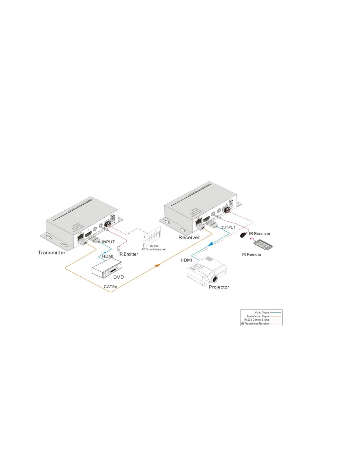
3.2 System Diagram
3.3 Connection Procedure
Step1. Connect HDMI source (such as Blue-ray DVD) to HDMI IN port of transmitter
Transmitter with HDMI cable.
Step2. Connect HDBT OUT port of Transmitter and HDBT IN port of Receiver, with single
CAT5e/CAT6 cable.
Step3. Connect HDMI displayer (such as HDTV) to HDMI OUT port of Receiver with HDMI
cable.
Step4. Both Transmitter and Receiver have IR IN and OUT. When one end is used a s an
IR receiver, the signal sent from the end can only be transmitted via the other end.
For example: When “IR IN” of Transmitter connects with an IR receiver, the IR
Page 8
Seite 8 von 13
transmitter must connect to IR OUT of Receiver.
Step5. Connect the RS232 port of the devices to be controlled and the receiver or the
transmitter.
Connect with DC24V power adaptor(s) (One is enough if any end of Transmitter and
Receiver is connected with adapter as its PoC function).
3.4 Application
The Extender has a good application in various occasions, such as computer realm,
monitoring, big screen displaying, meeting room, education and bank & securities
institution etc.
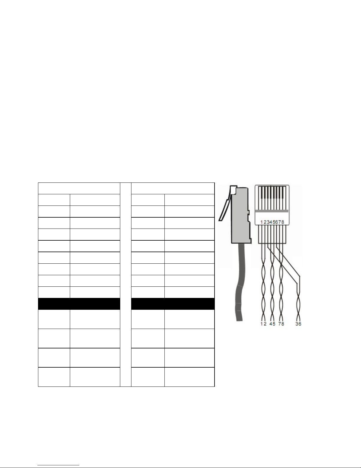
3.5 Twisted Pair Cable Connection
The twisted pair used in this extender MUST be a straight-through cab le.
Notice: Cable connectors
MUST be metal one, the
shielded layer of cable MUST
be connected to the connector’s
metal shell, to make a better
transmission.
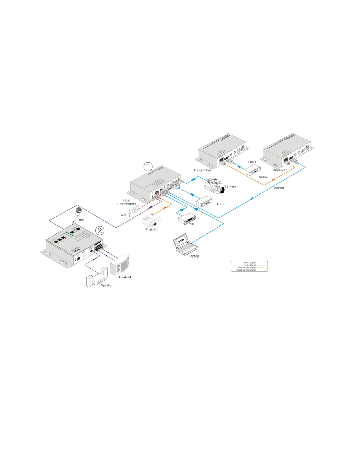
3.6 Collocation Products
The Extender usually work together with other devices to extend the transmission distance
of HDMI/IR/RS232 signal. Here are the most common collocation products.
TIA/EIA T568A
TIA/EIA T 568B
Pin Cable color Pin Cable color
1
green white
1
orange white
2
green
2
orange
3 orange white 3 green white
4
blue
4
blue
5
blue white
5
blue white
6 orange 6 green
7 brown white 7 brown white
8
brown
8
brown
1st
Ground
4--5
1st
Ground
4--5
2nd
Ground
3--6
2nd
Ground
1--2
3rd
Group
1--2
3rd
Group
3--6
4th
Group
7--8
4th
Group
7--8
Page 9
Seite 9 von 13
Description:
1) SC61D (mini scaler switcher)
6 video Inputs: 2 x HDMI, 1 x VGA, 1 x YPbPr, 1 x C-video & 1 x S-video, and upscale
to HDMI output at 1080P.
Support VGA resolutions: 640x480, 800x600, 1024x768, 1280x1024, 1280x768,
1360x768@60Hz, 1920x1080.
Built-in PAL/NTSC and audio format automat ic ide ntification technologies, with good
video and audio processing technology for high performance.
3 audio outputs: HDMI embedded audio, 3.5mm stereo audio and Coaxial (SPDIF).
Output display H/V size, position, image color adjustable and output image freezable.
Built-in breakpoint memory and power-of f prote cti on f unct ion .
2) PA2B (mini digital amplifier)
2x20Watt@4Ohm as the default amplifier output.
Page 10
Seite 10 von 13
Bridge connection function. User can switch the PA2B to be 1x40Watt@8Ohm by
bridge connection.
48V phantom power to support condenser microph one.
MIC port can support balance/unbalance signal, suppress the external noise effectively.
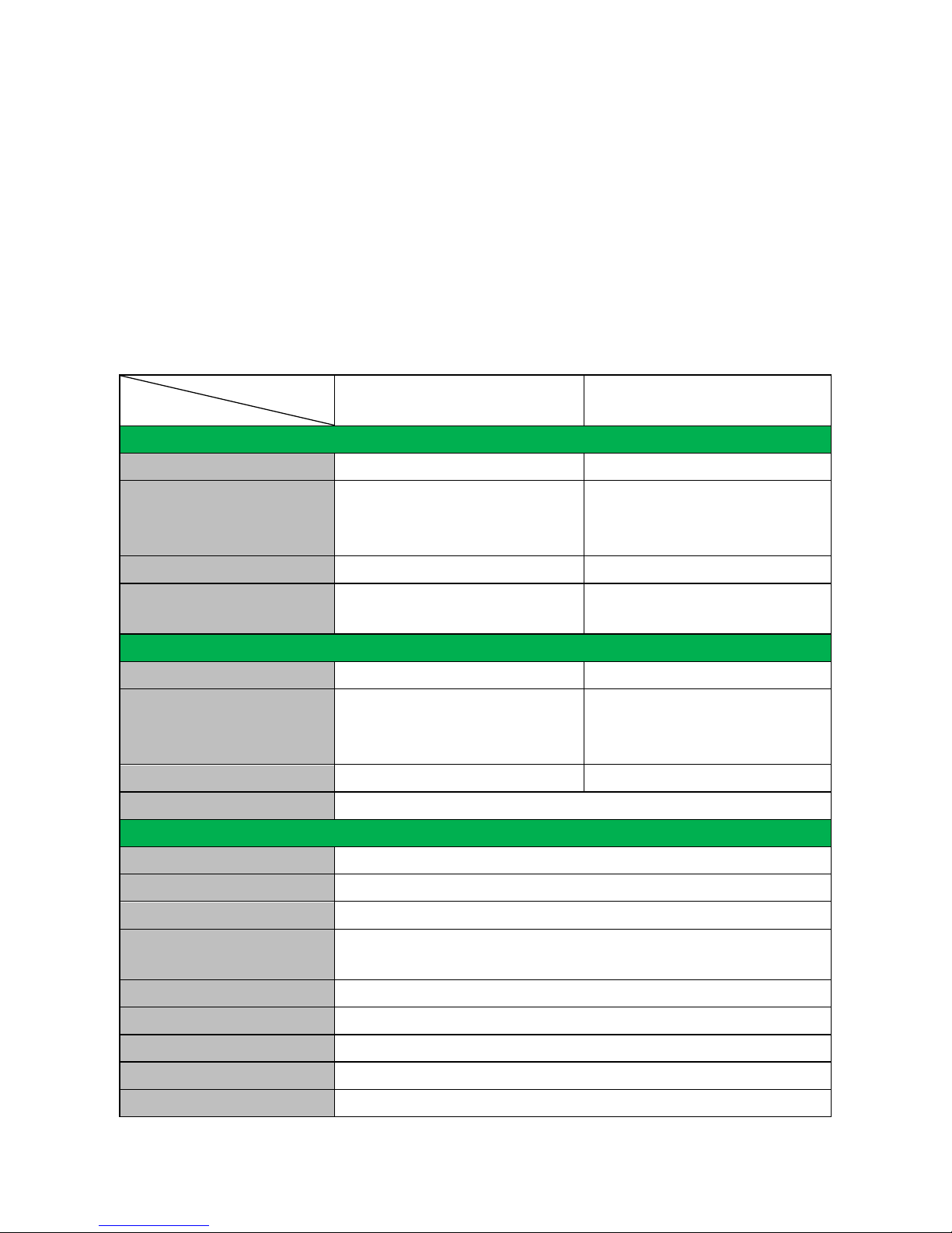
4. Specification
Model
Spec
Transmitter Receiver
Input
Input Signal
1 HDMI,1 IR & 1 RS232
1 IR, 1 RJ-45 & 1 RS232
Input Connector
HDMI female, 3.5mm mini
jack, 3p captive screw
connector
3.5mm mini jack, RJ-45,
3p captive screw
connector
Video Signal
HDMI1.4
HDMI1.4
Audio
Digital audio, transmit
through HDMI audio
Digital audio, transmit
through HDMI audio
Output
Output
1 RJ-45, 1 IR, 1 RS232
1 HDMI, 1 IR, 1RS232
Output Connector
RJ-45, 3.5mm mini jack, 3p
captive screw connector
HDMI female, 3.5mm mini
jack, 3p captive screw
connector
Video signal
HDMI1.4
HDMI1.4
Transmission Mode
HDBase T
General
Resolution Range
800x600 ~ 1920x1200,3D,4Kx2K
Transmission Distance
Max distance 70M
Gain
0dB ~ 10dB@100MHz
Differential Phase
Error
±10° @ 135MHz_100M
SNR
>70dB@ 100MHz-100M
Bandwidth
10.2Gbps
Return Lost
<
-30dB@5KHz
THD <0.005%@1KHz
HDMI Standard
Support HDMI1.4 and HDCP
Page 11
Seite 11 von 13
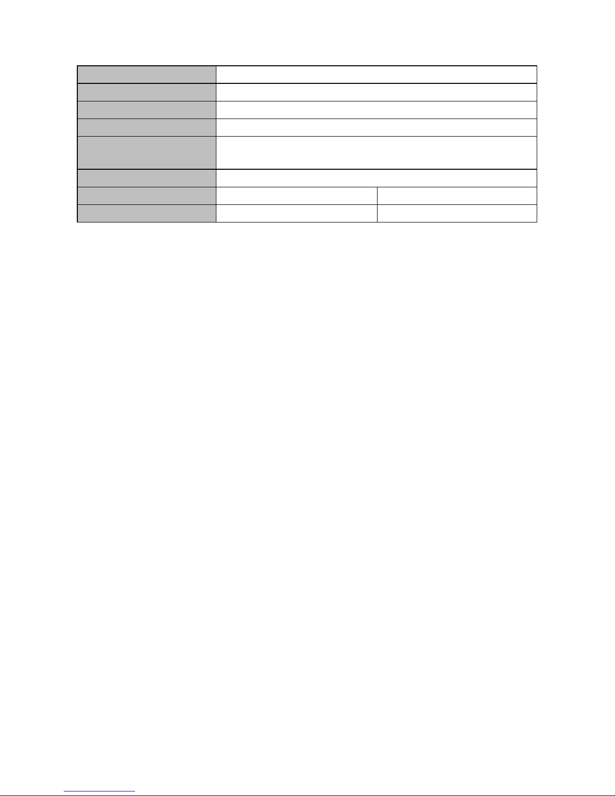
Min. ~Max. Level
<
0.3V ~ 1.45Vp-p
Impedance
75Ω
Temperature
-20 ~ +70℃
Humidity
10% ~ 90%
Power Supply Input: 100VAC~240VAC, 50/60Hz Output: DC 24V,
1.25A
Power Consumption
9.6W
Case D imension
W110.16xH28x D77 (mm)
W113.03xH28x D77 (mm)
Net Weight
0.5Kg
0.5Kg
NOTE: All nominal levels are at ±10%.
5. Troubleshooting & Maintenance
1) When images of terminal unit output with ghost, such as the projector output with ghost.
Generally this is not a unit faulty, this may be caused by an incorrect setting on the
projector or a bad quality of cable. Please check the projector’s setting or try another
high quality connection cabl e.
2) When there is a color losing or no video signal output, please check the input and
output end connections of the cables.
3) When user cannot control the extender by computer through its COM port, please
check the COM port number in the software and make sure the COM port is in good
condition.
4) When switching, there is no output image:
Check with oscilloscope or multimeter if there is any signal at the input end. If
there is no signal input, it may be the input connection cord broken or the
connectors loosen.
Check with oscilloscope or multimeter if there is any signal at the output end. If
there is no signal output, it may be the output connection cord broken or the
connectors loosen.
If it is still the same after the above checking, maybe there is something wrong in
the extender. Please send it to the dealer for fixing.
If the static becomes stronger when connecting the video connectors, it probably due to
bad grounding, please check the grounding and make sure it connected well, otherwise it
would damage the extender
Page 12

Seite 12 von 13
Page 13

Seite 13 von 13
SOMMER CABLE GmbH
Humboldtstraße 32-36
75334 Straubenhar dt / Germany
Tel: +49 (0)7082-49133-0
Fax: +49 (0)7082-49133-11
Email: [email protected]
Website: www.sommercable.com
 Loading...