

Page 1
Z-Wave RTS Interface Preliminary Instructions (ZRTSI)
Somfy Part # 1870202
Product Overview
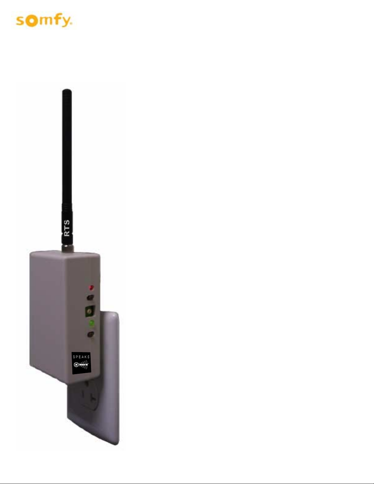
The Somfy Z-Wave Universal RTS Interface (“ZRTSI”) is a Z-Wave
bridge controller that resides as a secondary controller (only) node
within a designated Z-Wave control network. It receives Z-Wave
transmissions and coverts them to motor control commands for
Somfy’s full range of RTS wireless controlled motors. It is
recommended that one interface be used for each RTS motor area
within a 25-35 foot radius of the interface.
The ZRTSI has sixteen (16) virtual Z-Wave nodes that correspond to
sixteen (16) RTS channels. All nodes can be automatically included
with a Somfy TaHoma primary controller #1811151 (or other Z-Wave
SIS controllers). Individual nodes can also be manually included in
the network with TaHoma or other standard Z-Wave controllers.
RTS channels are linked to Somfy RTS embedded motors per the
RTS programming instructions for each RTS motor type.
The ZRTSI is powered when plugged into an active receptacle.
Z-Wave Certification
♦ This device is Z-Wave certified pending and can be
controlled by all Z-Wave certified controllers.
Page 1 of 5
Page 2
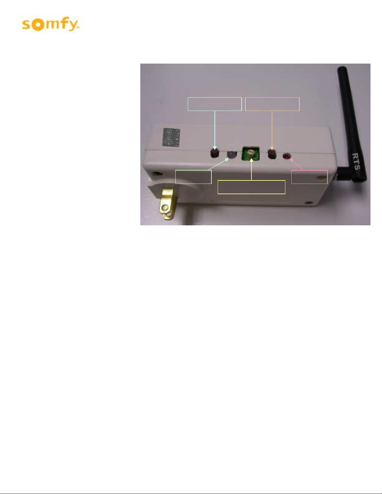
Z- LED
Z-
BUTTON
Rotary Selector
S-
LED
S-
BUTTON
ZRTSI Ins t allation and Operating Instructions
Programming and operation
buttons and indicators are
found on the side of the
ZRTSI as illustrated.
The ZRTSI must be plugged
into an AC power outlet within
Z-Wave and RTS
transmission ranges for
programming and operation.
Buttons & Indicators
S-BUTTON - The S-BUTTON has 4 primary purposes:
1. Used for binding RTS Channel s t o S omfy RTS motors.
2. Used for manually incl uding or excluding the ZRTSI into or out-of a Zwave network.
3. Used for verifyi ng RTS c ommunication between the ZRTSI and an RTS motor. Repeatedly pressing
and releasing the S-BUTTON while in Normal Mode (see Mode Descriptions) will drive an RTS motor
UP-STOP-DOWN etc.
4. Used for accessing inc lusion mode or exclusion mode when pressed & held during power-up
(see Mode Descriptions).
S-LED - The S- LE D changes 3 different colors:
1. Green – indicates norm al m ode of operation.
2. Red – flashing red indicates that an RTS transmission is occurring.
3. Yellow - Soli d yell ow indic ates that a manual node inclusion i s permitt ed.
Flashing yellow indicates that manual node ex cl usi on is permitted.
ROTARY
SELECTOR – The Rotary Selector is used to select individual virtual Z-Wav e nodes or individual RTS channels.
There are sixteen (16) total node/c hannels; Channels 1-9, Channel 10 = A, Channel 11 = B,
Channel 12 = C, Channel 13 = D, Channel 14 = E, Channel 15 = F, Channel 16 = 0.
Page 2 of 5
Page 3

Z-BUTTON – The Z-BUTTON has 3 primary purposes:
1. Used for manually incl uding the ZRTSI main node to a Zwave network.
2. Used for automatically including (with a SIS cont roller) all virtual nodes to a ZWav e network.
3. Used for resetting the ZRTSI Z-Wave chip to factory default s when pressed & held together with the
S-BUTTON upon power-up (see Mode Descriptions).
Z-LED - The Z-LED will be on during power-up of the ZRTSI. If the ZRTSI is incl uded in a network, the LED will
remain on. If the ZRTSI is not incl uded in a network, the LED will turn off after 5 seconds. The Z- LED wil l
also flash during automatic inclusion of the v irtual nodes.
Mode Descriptions
Normal Mode - (also known as Green Mode) – Inserting the ZRTSI into an AC outlet will turn the S-LED green and
enable Normal Mode. This means the ZRTSI is prepared for normal operation or programming. Normal Mode can al so
be enabled from Zwave Include or Exclude Modes (see Programm ing) .
Factory Default Mode – With the ZRTSI remov ed from the A C outlet , pr ess & hold the Z-BUTTON. While holding
the button, insert the ZRTSI into the AC outlet. Continue holding the Z-BUTTON while the Z wav e chi p and PIC variables
are reset (approximately 10 seconds). The LEDs will flash during this time, and when reset i s complete the S-LED will
be GREEN and the Z-LED will be off. Please note that Factory Default does not reset any RTS programming.
Z-Wave Node Include Mode - (also known as Solid Yellow Mode) – With the ZRTSI removed from the AC outlet,
press & hold the the S-BUTTON. While holding the button, insert the ZRTSI into the AC outlet. Conti nue holding the
S-BUTTON while I ncl ude M ode is bei ng initiated. The S-LED will fl ash for approximately 6 seconds during this time,
and Include Mode will be enabled when the S-LED is solid yellow. Release the S-B UTT ON after the S-LED turns solid
yellow.
Z-Wave Node Exclusion Mode - (also known as Flashing Yellow Mode) – With the Z wav e Include M ode enabled
(see above), press & hold the S-Button for approximat el y 3 seconds until the S-LED begins to flash yellow. Release
the S-BUTTON whil e the S- LE D is fl ashi ng y ellow.
Factory Default / Include Mode – The ZRTSI can be reset to Factory Default and Node Include Mode in one step
if desired. With the Z RTSI rem ov ed from the AC outlet, press & hold the Z -BUTTON and S-BUTTON together
holding the butt ons, insert the ZRTSI into the AC outlet. Conti nue holding both buttons while the Zwave c hip is reset and
Include Mode is enabl ed - this may take about 17 seconds. When the S-LED turns solid yell ow, release the buttons.
. While
PROGRAMMING
Add ZRTSI Base Node & ALL 16 Virtual Nodes to a Primary Z-Wave (SIS) Controller Automatically
1. Verify that t he ZRTSI is not incl uded in a Zwave network.
2. Enable the “Listening Mode” on the SIS controller .
3. Enable the Zwave Node I ncl ude M ode on the Z RTSI.
4. Press & hold the Z-BUTTON until the Z-LED begins to flash (approximately 3 seconds). The Base Node
and 16 Virtual Nodes wil l be added to the SIS controller. This process may take several minutes, and the
Z-LED will flash rapi dly from time to time. The process is complete when the Z-LED stays solid red for 15
seconds or until all 16 virtual nodes appear with your SIS cont r oller.
Page 3 of 5
Page 4

Add ZRTSI Base Node (Bridge Controller) Only
1. Verify that t he ZRTSI is not incl uded in a Zwave network.
2. Enable the “Listening Mode” on the SIS controller .
3. Enable the Zwave Node I ncl ude M ode on the Z RTSI.
4. Press & release the Z-BUTTON. The Z-LED will fl ash rapidly, then turn solid red when the process is
complete.
Add a Z-Wave Virtual Node Manually
1. Enable the “Listening Mode” on the SIS controller .
2. Enable the Zwave Node I ncl ude M ode on the Z RTSI.
3. Select the desired RTS c hannel on the Rotary Selector
4. Press the S-BUTTON for 1 second.
NOTE - If no SIS controller is present, each node, including the main bridge node m us t be included manually.
Remove a ZWave Virtual Node Manually
1. Enable the “Listening Mode” on the SIS controller .
2. Enable the Zwave Node Ex cl ude M ode on the Z RTSI.
3. Select the desired RTS c hannel on the Rotary Selector.
4. Press the S-BUTTON for 1 second.
Enable Normal Mode from Include or Exclude Mode
1. While the ZRTSI is in eit her Include or Exclude Mode (solid yellow or flashing yellow), press and hold the
S-BUTTON until the S - LE D turns Gr een. Thi s may take several seconds.
2. When the S-LED turns Gr een, Norm al M ode is enabled.
Binding an RTS Channel to a Motor
1. Enable the Normal Mode on the ZRT SI.
2. Refer to the RTS Motor instructions, and place the RTS Motor into Pr ogr amming Mode.
3. Select the desired RTS c hannel on the Rotary Selector.
4. Press & hold the S-BUTTON until the S-LED flashes and the RTS motor jogs. The joggi ng will indicate that the
RTS channel has been accepted.
5. Verify RTS comm unic ation between the ZRTSI and the RTS Motor by pressing and releasi ng the S-BUTTON.
Successiv el y pressing and releasing the S-BUTTON should dr ive the motor UP-STOP-DOWN-STOP- and so
on.
Page 4 of 5
Page 5

Note:
1. The ZRTSI is intended for professional installation only. It requires specific configuration tools that are only available to S omfy’s trained
distribution. Without these tools, the ZRTS can not be made functional
2. Antenna Specifications ( Part # : G-RAOK10110003-C0026)
a. Omni Directional
b. 50 Ohm Impedance
c. 1.57 Max Gain
FCC INFORMATION
This device complies with Part 15 of the FCC Results. Operation is subject to the following two conditions:
1. This device may not c aus e har mful interferenc e, and
2. This device must ac cept any int er f erence received, inc luding that whic h m ay c ause undes ired oper ati on.
NOTE: This equipment has been tested and found to comply with the limits for CLASS B digital device, pursuant to Part 15 of FCC Rules. These limits
are desig n ed to provid e reas on able prot ec ti on ag ainst har mf ul interfer enc e wh en the eq uipment is op erated in a com m er c i al en vironment.
This equi p m ent g enerates , us es and c an radiate r adi o frequenc y energy and, if not ins t alled and us ed in ac cordanc e wi th the instructions,
may cause harmful interference to radio communications. However, there is no guarantee that interference will not occur in a partic ul ar install ati on.
If this equipment does cause harmful interference to radio or television reception, which can be determined by turning the equipment off and on, the
user is encouraged to try to correct the interference by one or more of the following measures:
Changes or mod if ications n ot expressly appr oved b y the m an ufactur er c ould void the us er ’s aut hority to op erate the eq ui pm en t.
1. Reorient or relocate the receiving antenna
2. Increase the separation between the equipment and receiver
3. Connect the equipment into an outlet on a circuit different from that to which receiver is connected
4. Consult the dealer or experienced radio/TV technician for help.
WARNING
Page 5 of 5
 Loading...