

Page 1

ZWAVE to RTS INTERFACE
Specification, Installation & Operating Instructions
DESCRIPTION
Z-WAVE TECHNICAL SPECIFICATIONS
A. Controller Bridge Node
- Main Controller Bridge Node is the repeating Node
- Bridge Node supports Network Wide Inclusion (NWI)
- Manufacturer ID: 00 47 (Somfy)
- Product Type: 5A 52
- Product ID: 54 00
- ZWave firmware: Controller Bridge Library 3.20
- ZWave Series Chip: 300 Series
The Somfy Z-Wave Universal RTS Interface (ZRTSI) is a Z-Wave bridge controller
that resides as a secondary controller node within a designated Z-Wave control
network. It receives Z-Wave transmissions and converts them to motor control
commands for Somfy”s full range of RTS wireless products.
The ZRTSI has 16 virtual ZWave nodes that correspond to 16 RTS channels. All
nodes can be automatically included with a Somfy TaHOma primary controller
(1811151) or other ZWave controllers. Individual nodes can be also manually
included in the network.
Command Classes Supported By Bridge Node
- Controller_Replication
- Version
- Manufacturer_Specific
- Basic Device Class: Basic_Type_Static_Controller
- Generic Device Class: Generic_Type_Static_Controller
- Specific Device Class: Specific_Type_Not_Used
B. Virtual Nodes
- Manufacturer ID: 00 47
- Product Type: 51 52
- Product ID: 54 xx
XX will be 01 - 16, which represents the RTS channel. For example, if the product ID is 54 08, then it
correspons to RTS channel 8.
Command Classes Supported By Virtual Nodes
- Version
- Manufacturer_Specific
- Switch_Multilevel
- Switch_Binary
- Scene_Activation
- Scene_Actuator_Conf
- Basic Device Class: Basic_Type_Slave
- Generic Device Class: Generic_Type_Switch_Multilevel
- Specific Device Class: Specific_Type_Calss_A_Motor_Control
Page 2
PROGRAMMING INSTRUCTIONS
1
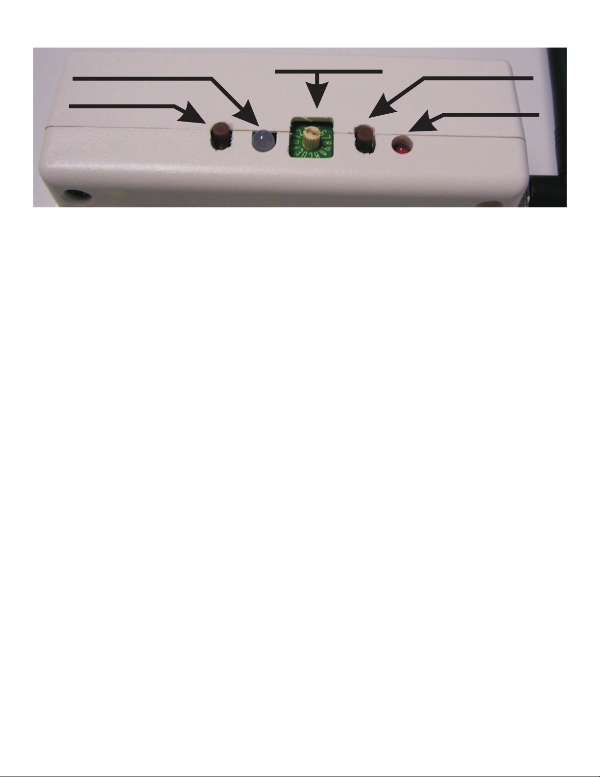
S - LED
Rotary Selector
S - Button
FIGURE 1: ZWave URTSI Buttons and Indicator Layout
AUTOMATICALLY ADDING THE BASE NODE AND ALL 16 VIRTUAL NODES
1. Verify that the ZRTSI is not included in a ZWave network.
2. Enable the Listening Mode on the SIS Controller
3. Enable the ZWave Node Include Mode on the ZRTSI
A. With the ZRTSI unplugged, press and hold the S-Button. Continue holding the button while you plug in the ZRTSI. The S-LED will flash for about 6 seconds.
B. Release the S-Button after the S-LED turns solid yellow.
4. Press and Hold the Z-Button for about 3 seconds until the Z-LED begins to flash. The Base Node and 16 Virtual Nodes will be added to the
SIS Controller. This process may take several minutes ant the Z-LED will flash rapidly from time to time.
5. The process is complete with the Z-LED stays solid red for 15 seconds or until all 16 virtual nodes appear in your SIS Control.
Z - Button
Z - LED
ADDING ONLY THE BASE NODE
2
3
4
1. Verify that the ZRTSI is not included in a ZWave network.
2. Enable the Listening Mode on the SIS Controller
3. Enable the ZWave Node Include Mode on the ZRTSI
A. With the ZRTSI unplugged, press and hold the S-Button. Continue holding the button while you plug in the ZRTSI. The S-LED will flash for about 6 seconds.
B. Release the S-Button after the S-LED turns solid yellow.
4. Press and release the Z-Button. The Z-LED will flash rapidly.
5. The process is complete with the Z-LED stays solid red.
ADDING or REMOVING A VIRTUAL NODE MANUALLY
1. Enable the Listening Mode on the SIS Controller
2. Enable the ZWave Node Include Mode on the ZRTSI
A. With the ZRTSI unplugged, press and hold the S-Button. Continue holding the button while you plug in the ZRTSI. The S-LED will flash for about 6 seconds.
B. Release the S-Button after the S-LED turns solid yellow.
4. Use the Rotary Selector to choose the RTS Channel. Positions 1 - 9 are equivalent to RTS Channels 1 - 9. Positions A - F are equivalent to RTS
Channels 10 - 15. Position 0 is equivalent to RTS Channel 16.
5. Press the S-Button for 1 second.
6. Repeating steps 1 - 5 above will Remove the Virtual Node.
PROGRAMMING AN RTS CHANNEL
1. Enable Normal Mode on the ZRTSI
A. Press and hold the S-Button until the S-LED turns green. This may take several seconds.
2. According to the specific product instructions, place the RTS motor or control in Programming Mode.
3. Use the Rotary Selector to choose the RTS Channel. Positions 1 - 9 are equivalent to RTS Channels 1 - 9. Positions A - F are equivalent to RTS
Channels 10 - 15. Position 0 is equivalent to RTS Channel 16.
4. Press and hold the S-Button until the S-LED flashes and the RTS product responds (motor will jog). This indicates the RTS channel has been
memorized.
5. Verify RTS communication by pressing and releasing the S-Button. Each press of the button will sequence through UP - STOP - DOWN - STOP.
Page 3

S - LED
Rotary Selector
Z - Button
S - Button
Z - LED
FIGURE 1: ZWave URTSI Buttons and Indicator Layout
SUMMARY - MODE DESCRIPTIONS
NORMAL MODE
1. Inserting the ZRTSI into an AC outlet will turn the S-LED green and enable Normal Mode. This means the ZRTSI is prepared for normal
operation.
2. If the ZRTSI is in Include or Exclude Mode (S-LED is flashing or solid yellow), Normal Mode can be entered by pressing and holding the
S-Button until the S-LED turns green.
FACTORY DEFAULT MODE
1. With the ZRTSI unplugged, press and hold the Z-Button. Continue holding the button while plugging the unit into an outlet. Continue
holding the Z-Button while the LEDs flash.
2. The ZRTSI is in Factory Default when the S-LED is green and the Z-LED is off.
ZWAVE NODE INCLUDE MODE
1. With the ZRTSI unplugged, press and hold the S-Button. Continue holding the button while you plug in the ZRTSI. The S-LED will flash
for about 6 seconds.
2. Release the S-Button after the S-LED turns solid yellow.
ZWAVE NODE EXCLUSION MODE (Virtual Nodes Only)
1. Follow the steps above for ZWave Include Mode.
2. Press and hold the S-Button for 3 seconds until the S-LED begins to flash yellow.
3. Release the S-Button while the S-LED is still flashing.
FACTORY DEFAULT INTO INCLUDE MODE
1. To reset the ZRTSI and enter into Include Mode in one step, with the ZRTSI unplugged, press and hold the S-Button and Z-Button together.
2. Continue holding the both button while you plug in the ZRTSI and continue holding for about 20 seconds until the S-LED turns solid yellow.
SUMMARY - BUTTONS & INDICATORS
S-BUTTON
- Used for Programming RTS Channels to Somfy RTS Motors or Controls.
- Used for manually including or excluding the ZRTSI in or out of a ZWave network
- Used to verify RTS communication between the ZRTSI and an RTS motor or control
- Used for entering Include or Exclude mode when pressed and held during power up.
S-LED
- When green, indicates Normal Mode
- Flashing Red indicates that an RTS transmission is occurring.
- Solid yellow shows that a manual node inclusion is allowed
- Flashing yellow shows that a manual node exclusion is allowed
ROTARY SELECTOR Used to select individual virtual ZWave nodes or RTS Channels
Z-BUTTON
- Used when manually including the ZRTSI main node to a ZWave network
- Used for automatically including all virtual nodes
- Used to reset the ZRTSI to Factory Default Mode
Z-LED
- On during power up, turns off after 5 seconds
- If the ZRTSI is included in a network, the LED will remain on
- Flashes during automatic inclusion of the virtual nodes.
 Loading...