

SOMFY Z-Wave2RTS Product Manual
DCT2RTS interface and Z-Wave2RTS interface
Product manual
SAFETY AND IMPORTANT INFORMATION
• This Somfy product must be installed by a professional installer, for whom these instructions
are intended.
• Before installation, check that this product is compatible with the associated equipment and
accessories.
• These instructions describe how to do installation, commission and use this product.
• Moreover, the installer must comply with current standards and legislation in the country in
which the product is being installed, and inform his customers of the operating and
maintenance conditions for the product.
• Any use outside the sphere of application specified by Somfy is not approved. Such use, or any
failure to comply with the instructions given herein will invalidate the warranty, and Somfy
refuses to accept liability.
• The equipment (interface) is for built-in use.
CAUTIONS
• Always remove the micro-USB cable horizontally and gently. Incorrect removal could cause
damage to the USB port.
• The output voltage of micro-USB power adaptor cannot exceed 5VDC @500mA
• The interface must be installed securely in a fixed position which allows a steady and level USB
input.
• Do not install the interface in metal cases as it may affect the radio signal strength.
• Install the device on the fixed mounting, e.g wall.
• Avoid dust and water, which may damage the device.
• The DCT2RTS interface and Z-WAVE2RTS interface are for internal use only.
• Do not disassemble the unit.
PRODUCT DESCRIPTION
• DCT2RTS gateway: Provides communication between third party home automation systems
and RTS motors through simple dry contact input interface.
• Z-Wave2RTS interface: Z-Wave enabled device (interoperable, two-way RF mesh networking
technology) that is fully compatible with any Z-Wave enabled network. Receives Z-Wave
signals and translates them into RTS commands to allow control of Somfy RTS enabled motors.
The Z-Wave2RTS interface supports mulit-channel Command Class for up to 8 devices
corresponding to control of up to 8 individual or 8 groups of Somfy motorized products.
Z-Wave enabled device acts as a signal repeater and multiple devices result in more possible
transmission routes which helps eliminate “RF dead-spots”.
Z-Wave enabled device displaying the Z-Wave logo can also be used with it regardless of the
manufacturer, and ours can also be used in other manufacturer’s Z-Wave enabled networks.
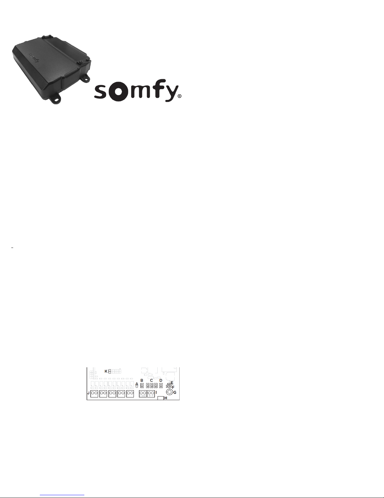
DCT2RTS, Z-WAVE2RTS
interface functions
description
A – RTS LED / Status LED
Green: Power ON
Blue: Transmitting RTS command
Red: Error
B – RTS Program button
C – RTS test buttons for UP/DOWN/STOP
D – Z-WAVE program button
E – Z-WAVE LED
Flash: Open to add Z-WAVE network
OFF: Z-WAVE network added
Please select either “Fixed position switch mode” or “Momentary switch mode” by the jumper
(item K) before powering ON the device.
• Jumper close (short)=Momentary switch (default)
• Jumper open=Fixed position switch
F – Reset button
G – RTS channel selector
H - 5VDC micro-USB port (*optional)
I – 12-24V DC input port
K – Switch type selection
Fig.1
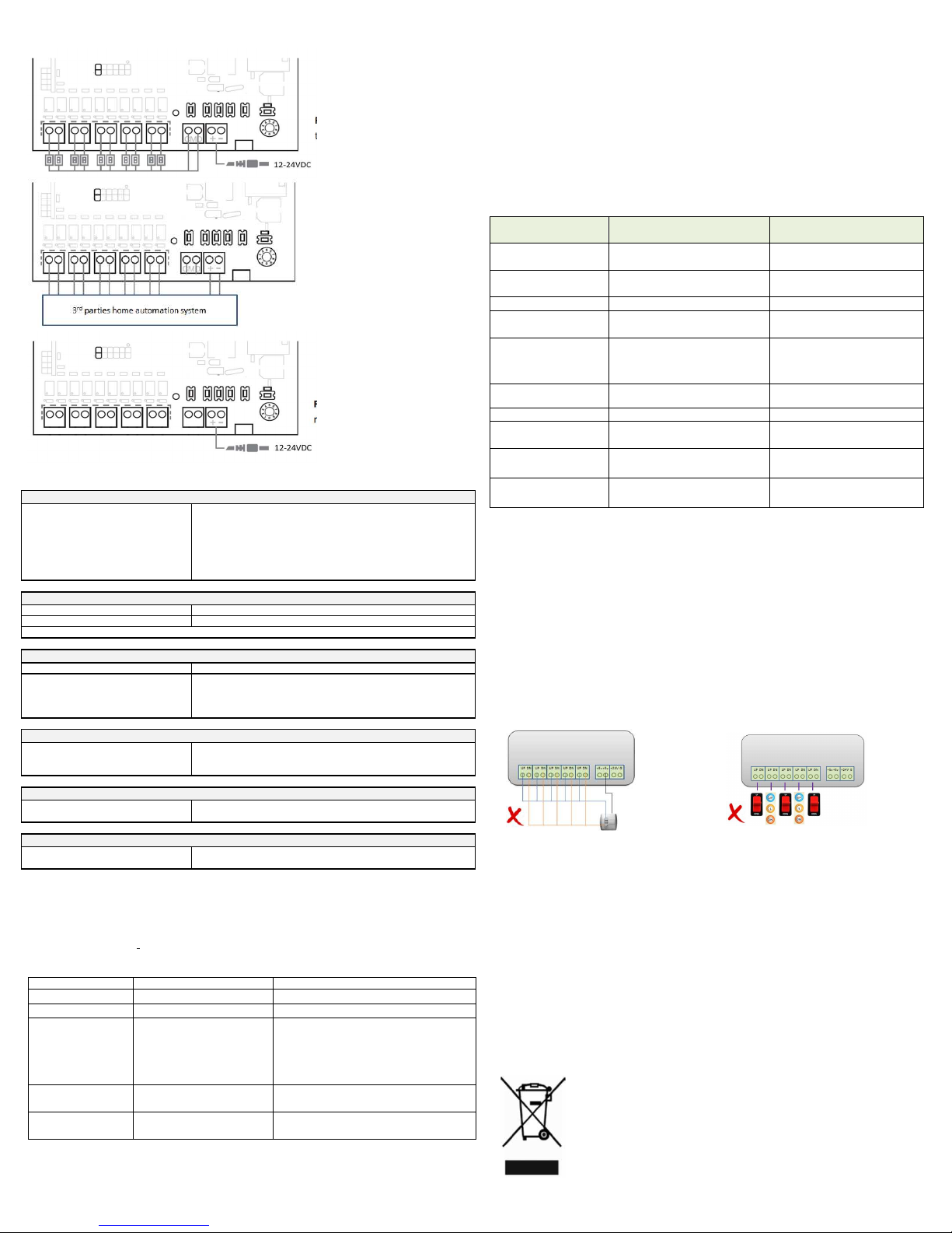
DCT2RTS interface setting
1. Installation
1.1. Disconnect the power
1.2. Select which type of switch will be connected (fig.1)
1.3. Wire either switches (fig.2) or dry-contact relay outputs (fig.3) to the indicated DCT
terminals at the bottom of the DCT2RTS Interface.
1.4. Connect the power. The status LED will turn green to indicate the device is operating.
2. RTS commissioning
Before using the DCT2RTS interface, we recommend programming each motor in advance
using an individual Somfy remote control (e.g. Telis) and set the limit positions of each motor.
Procedure
2.1. Select the channel of the motor on the existing remote control, hold the program
button on the remote for 3 seconds, for the motor to jog
2.2. Select the desired channel (channel 1 – channel 5) via the RTS channel selector.
2.3. Press and hold the RTS PROG button for 1 second.
2.4. RTS motor jogs; the motor is now programmed to DCT2RTS gateway.
2.5. Repeat the same procedure to remove a motor from the DCT2RTS gateway.
RTS motors functional test
2.6. Select the channel via the RTS channel selector.
2.7. Press the UP/DOWN button on DCT2RTS interface to control RTS motors.
2.8. The motor jogs to indicate the connection is successfully established. If the motor doe s
not respond to the command, it means the establishment failed. Repeat 1.2.1 Procedure,
Steps 1-4 again. Alternately it may simply mean that the RTS motor has been removed.
3. Operation
3.1. To activate an UP command, a minimum of 0.5 second closure is required between the
UP and COM terminals (5VDC). The status LED turns blue to indicate that RTS signal is
sent.
3.2. To activate a DOWN command, a minimum of 0.5 second closure is required between
the DOWN and COM terminals (5VDC). The status LED turns blue to indicate that RTS
signal is sent.
3.3. To activate a STOP command, a closure is required between UP, DOWN and CMD
terminals.
Attention: Press and hold the RTS_PR OG button for 5 seconds, the concerned RTS motor will
enter to RTS programming mode.
Z-Wave2RTS interface setting
1. Installation
1.1 Disconnect the power (fig.4)
1.2 Locate the Z-Wave2RTS interface within direct range of the Z-Wave HUB.
1.3 Select the “appropriate channel number” on the RTS channel selector.
1.4 Connect the power. The status LED will turn green to indicate the device is operating.
1.5 The Z-WAVE LED will blink to indicate Z-WAVE2RTS interface is opened to add to Z-
!! The channel number selected should reflect the number of RTS channels being applied on ZWave Hub, for example, if 3 channels will be used, then select number 3 on the RTS channel
selector before powering on the Z-WAVE2RTS interface.
2. RTS commissioning
3. Z-Wave network commissioning
Tips: How the endpoint is used by the Z-Wave2RTS interface?
Z-Wave2RTS interface s upports Z-Wave multi-channels command class. Each endpoint represents
each RTS channel. For example, endpoint no.1 equal to RTS channel no.1, endpoint no.2 equal to
RTS channel no.2 and etc. All End Points have the same Generic and Specific Device Class and
Optional Command Classes.
Generic Device Class : GENERIC_TYPE_SWITCH_MULTILEVEL
Specific Device Class : SPECIFIC_TYPE_CLASS_A_MOTOR_CONTROL
Supported Command Classes : COMMAND_CLASS_ZWAVEPLUS_INFO,
WAVE network.
Z-Wave2RTS interface supports RTS channel 1 to channel 8. For details, please refer to
section 1.2.
Inclusion (Add Z-Wave2RTS interface to Z-Wave Hub)
3.1 Enable the Z-Wave HUB into the Inclusion mode.
3.2 Short press the Z-Wave PROG button for 3 times. Z-Wave2RTS interface will be added in
the Z-Wave network automatically.
3.3 The Z-WAVE LED turns OFF indicating that the Z-Wave2RTS interface has successfully
added the Z-Wave network.
Exclusion (Remove Z-Wave2RTS interface from Z-Wave Hub)
3.4 Power ON the Z-Wave2RTS interface.
3.5 Enable the Z-Wave HUB into exclusion mode.
3.6 Short press the Z-Wave PROG button for 3 times.
3.7 The Z-WAVE LED blinks indicating that the Z-Wave2RTS interface has successfully been
removed from the Z-Wave network.
Reset the Z-Wave module to factory modePlease use this procedure only in the event that
your network primary controller is missing or otherwise inoperable.
3.8 Power OFF the Z-Wave2RTS interface.
3.9 Press and hold the Z-Wave PROG button.
3.10 Power ON the Z-Wave2RTS interface and wait for 10 seconds.
3.11 The Z-Wave LED blinks indicating that the data is cleared and it is opened to add to Z-
Wave network.
COMMAND_CLASS_ASSOCIATION_GRP_INFO,
COMMAND_CLASS_ASSOCIATION_V2,
COMMAND_CLASS_SWITCH_MULTILEVEL_V4
Wiring diagram
DOWN Press DOWN
Press
DOWN
, then release (~1 sec)
While moving, Short
-
Press UP+DOWN
^
To stop Tilt, release DOWN button
Bina ry Switch Set (0xFF)
The bli nd goes UP.
Bina ry Switch Set (0x
00)The bli nd goes Down.
Group 1 s upports 1 node / EndPoi nt.
Report ZWave2RTS i nterfac e address to ZWAVE Hub (node) after reset.
5. Repeater fun ction
4. RESET Zwave module to factory mode
1. Include/Exclud e ZWAVE network
3. MultiChannel Association / Assoc iation (Control RTS motors via DCT switch)
COMMA
ND_CLASS_MANUFACTURER_SPECIFIC_V2
Z-Wave manual
ZWave2RTS i nterfac e wil l send s ignal s to Zwave Hub to perform the
Incl ude/Exclude a ction.
Press the ZWAVE_PROG button for 3 times.
2. RTS Output Control (Control RTS motors via Zwave Hub)
Note: Multi Chan nel CMD ENCAP V4 Command.
Group 2 s upports 5 nodes / EndPoints .
Press and hol d the ZWAVE_PROG button for 3
seconds after power ON to the ZWave2RTS
interfac e
The red LED on the ZWave2RTS interfac e blinks indic ating that i t has not add ed
ZWave network.
The red LED remains off when it has s uccess fully a dded to ZWave network.
Report DCT status to Hub (node) when DCT port is tri ggered. The DCT status
feedback s end to Hub automatica lly.
If EndPoi nt is defi ned, it will be use MultiCh annel Command to r eport the DCT
status
All Z-Wave data wi ll be cl eared and return to the In clusi on mode
Fig.2 Switches direct connect
to DCT2RTS interface wiring
Fig.3 Home automation system
directs connect to DCT2RTS
interface wiring
Fig. 4 Z-Wave2RTS interface
requires power supply only
Z-Wave command Class
Device Type : Window Covering No Position/Endpoint
Generic Device Class : GENERIC_TYPE_SWITCH_MULTILEVEL
Specific Device Class : SPECIFIC_TYPE_CLASS_A_MOTOR_CONTROL
Icon : ICON_TYPE_GENERIC_WINDOW_COVERING_NO_POSITION_ENDPOINT
COMMAND_CLASS_Z-WAVEPLUS_INFO
COMMAND_CLASS_ASSOCIATION_V2
COMMAND_CLASS_ASSOCIATION_GRP_INFO
COMMAND_CLASS_DEVICE_RESET_LOCALLY
COMMAND_CLASS_FIRMWARE_UPDATE_MD_V2
COMMAND_CLASS_MULTI_CHANNEL_V4
COMMAND_CLASS_MULTI_CHANNEL_ASSOCIATION_V3
COMMAND_CLASS_POWERLEVEL
COMMAND_CLASS_SWITCH_BINARY
COMMAND_CLASS_SWITCH_MULTILEVEL_V4
COMMAND_CLASS_VERSION_V2
Technical specification
Item Value Remark
Input voltage
(DC input port)
Input voltage
(Micro-USB port)
Operating current 200mA(max)
Dry contact input (DCT)
voltage
RTS radio frequency
Range distance
No of channel
No of channel
Z-Wave radio frequency
Range of distance
Operating Temperature 0°c to 50°c
Dimension (without cover)
Dimension (with cover)
Weight Z-Wave2RTS 138g
DC power 12-24VDC DC power transformer excluded
12VDC – 24VDC Main power to DCT2RTS interface
5VDC *Optional
5VDC – 24VDC Logic HIGH (VDC) triggers action.
433.42MHz
20m with 2 concrete walls
5
8
921.4 MHz
20m in indoor
125mm(L) x 88mm(W) x 30mm(H)
125mm(L) x 105mm(W) x 32mm (H)
DCT2RTS 134g
or Z-WAVE2RTS interface
Logic LOW (0V) clears action.
For DCT2RTS interface (ch1-5)
For Z-Wave2RTS interface (ch1-8)
AU-frequency
TIPS AND RECOMMENDATION FOR DCT2RTS interface
• The DCT2RTS interface requires 12-24VDC power. The power cable is connected to the power
terminal (item I) using the screw to fix it.
• To improve the RTS radio range, we recommend the DCT2RTS be placed in an unconfined
place in the middle of the house (avoid metallic surfaces and enclosures).
• In momentary switch mode, only press one button at a time.
• Tilting motion only apply on 1 channel at one time via DCT interface
• The DCT input must have at least 1.5 second suspension in between successive RTS commands.
• All DCT input port cannot be connected (short circuit) together. (fig.5)
• Does not support fixed position switch mode and momentary switch mode simultaneously.
See below picture. (fig. 6)
ZWave2RTS ga tewayZWave2RTS i nterface
suppor ts stand ard repeater functi on
6. OTA function
ZWave2RTS ga teway supp orts “Over The Air” to
upgrad e firmwar e.
Support repeaters for routing (i nclud e FLiRS devic es).
Support OTA-Fir mware update.
Switch compatibility Table
• Momentary switch (Default mode): It is only on when the button is pressed. As soon as you
release the button, the circuit is opened
• Fixed position switch: An on/off switch that rocks when pressed, which means one side of the
switch is raised while the other side is depressed much like a rocking horse rocking back and
forth
Blind movement Fixed position switch Momentary switch
UP Press UP Press UP, then release (~1 sec)
STOP After Press UP or DOWN
over 2 sec, then release #
Tilt UP N/A To start Tilt, Press UP (>2sec)*
Tilt Down N/A To start Tilt, Press DOWN (>2sec)*
# if button pressed over 5 minutes, STOP command will not send
* For non-tilt-able blinds, long-pressing UP/DOWN may trigger moving UP/DOWN fitfully
^ For blinds with My Position, short-press UP/DOWN button while the blinds are not moving, the
blinds will go to My Position
While moving up, short-press 1 more UP;
While moving down, short press 1 more
DOWN
OR
To stop Tilt, release UP button
Fig.5
Fig.6
TIPS AND RECOMMENDATION FOR Z-Wave2RTS interface
• Before power ON the device, please set the maximum number of RTS channels on RTS channel
selector (item G)
• The Z-Wave2RTS interface requires 12-24VDC power. The power cable is connected to the
power terminal (item I) using the screw to fix it. As an alternative, power can be supplied
through the 5VDC Micro-SUB if the proper adapter is used.
• Supply powers either 12-24VDC or 5VDC micro-USB input port. The device cannot be operated
by both power inputs together.
ENVIRONMENT
Damaged electric products and batteries should not be disposed of with normal household waste.
Make sure to drop them in specially provided containers or at an authorized organization that will
ensure they are recycled.
 Loading...