

Page 1
Sunis WireFree RTS Light Sensor
™
Programming/Operating/Installation Instructions
DESCRIPTION
The Sunis RTS Light Sensor is a wireless radio transmitter compatible with RTS motors and externally mounted RTS receivers.
Window or Sill mounted, the Sunis RTS operates motorized window coverings in accordance to the amount of sunlight received.
Sunlight sensitivity (threshold) can be adjusted for varying degrees of sunlight intensity.
Commands are transmitted by radio waves at 433.42 MHZ
Power: 3V Lithium battery, CR2430
Operating temperature: 0 deg. C/32 deg. F - +60 deg. C/140 deg. F
Range: Up to 65ft.
Mount: Window glass/sill
Dimensions: Diameter 2 3/16” /(55.5mm) x Depth 3/4” /(19mm)
Indoor Use Only
# 9013707
STEP ONE PROGRAMMING
ADDING A SUNIS WIREFREE RTS LIGHT SENSOR- INITIAL INSTALLATION
Note: During initial programming, provide power only to motor or RTS
receiver being programmed.
™
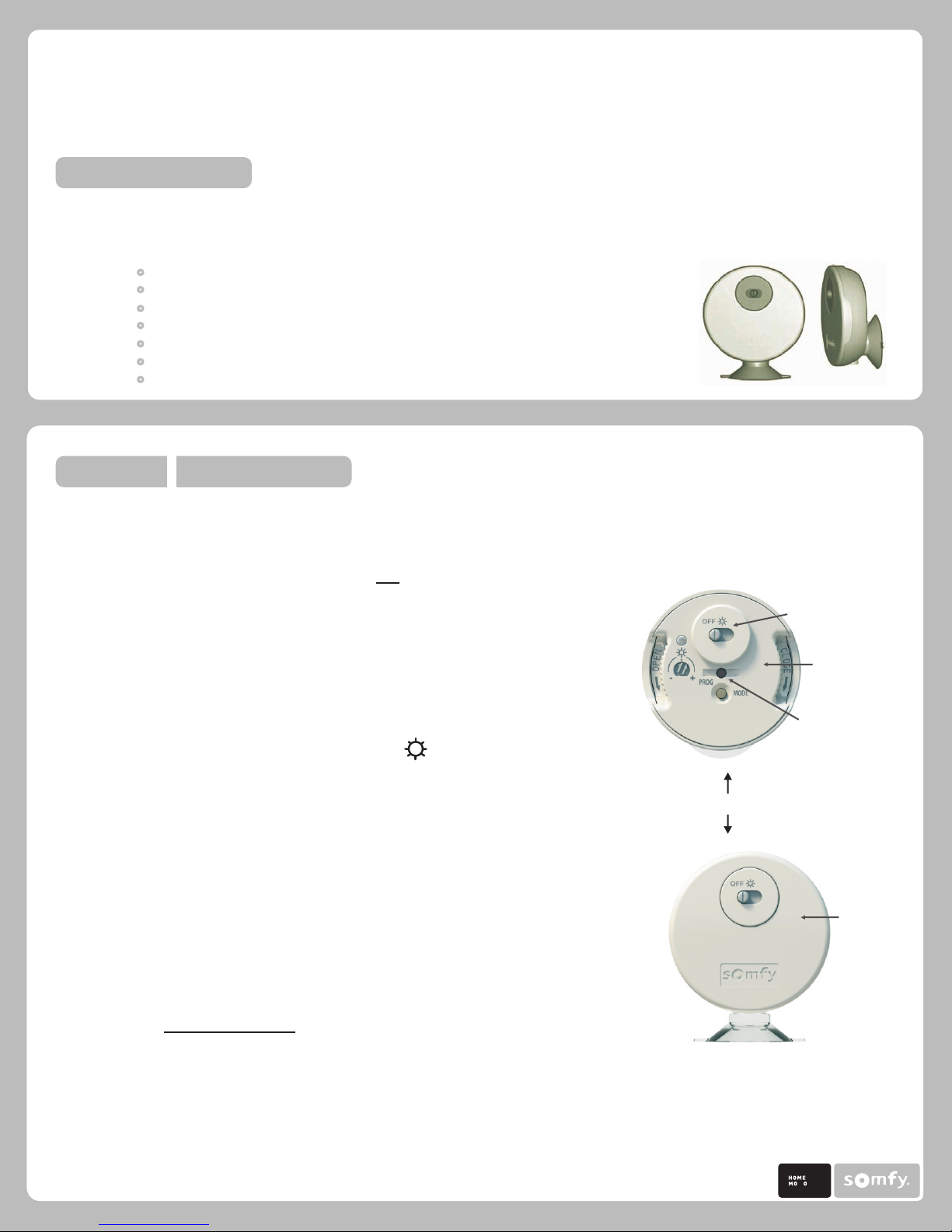
1. Carefully remove rear cover to expose sensor control setting panel.
2. Set the RTS Receiver or Motor into Programming Mode (Refer to the
installation instructions of the relevant RTS receiver or motor for this
procedure).
3. Slide the ON/OFF selector switch to the ON or Position
4. Using a paperclip or similar device, briefly press the programming button
(1 second max) located onthe Sunis light sensor. (See Figure 1) The RTS
receiver or Motor will confirm the addition of the new Sunis light sensor in
their respective manners.
Note: Repeat steps 1-3 when multiple motors are required to operate from the
Sunis light sensor
DELETING A SUNIS WIREFREE RTS LIGHT SENSOR FROM MEMORY
™
On/Off Selector Switch
Control
Setting Panel
Program Button
FIGURE 1
Rear Cover
1. Using a Paperclip or similar device, press and hold the program button (3 sec.)
on the previously addressed Sunis Light Sensor or Telis Transmitter. (See Figure 1)
The RTS receiver or motor will confirm programming mode in their respective
manners.
2. Using a paperclip or similar device, briefly press the programming button (1 sec. max)
located on the Sunis Light Sensor (See Figure 1.) The RTS receiver or Motor will confirm
the deletion of the Sunis Light Sensor in their respective manners.
TI N
BY
Page 2
Sunis WireFree RTS Light Sensor Programming/Operating/Installation Instructions
™
STEP TWO INSTALLATION
MOUNTING SUNIS WIREFREE LIGHT SENSOR TO WINDOW GLASS OR SILL
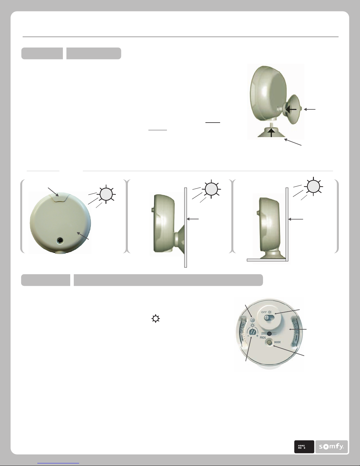
1. Attach the “screw-in" suction cup mounting device for Window Mount or Sill
Mount. (See Figure 2)
2. Determine the appropriate mounting location and throughly clean window glass
or sill area of debris or residue. Firmly press suction cup mount onto INSIDE window
(glass or sill) positioning sensor towards the OUTSIDE of window. (See Figure 3)
Note: Sunis light sensor MUST BE free from obstructions in order to correctly sense
incoming light. Sill mount may not be suitable for some window installations.
FIGURE 3
Sensor location
™
WINDOW GLASS MOUNT WINDOW SILL MOUNT
Outside of
Window Glass
FIGURE 2
Window
Glass Mount
OR
Window
Sill Mount
Outside of
Window Glass
Front of Sunis
towards outside
of window glass
STEP THREE SETTING THE LIGHT (SUN) SENSITIVITY (THRESHOLD)
1. Carefully remove rear cover of Sunis Light sensor exposing control
setting panel.
2. Slide the ON/OFF selector switch to the ON or Position
LED
Indicator
3. Momentarily press the Mode Button, LED Indicator will illuminate to a
red color for approx. 15 seconds.
Note: LED indicator light will remain illuminated for approximately 15 seconds.
Should the LED Indicator light extinguish prior to establishing the light sensitivity
(threshold) setting, simply press the MODE BUTTON momentarily to reactivate LED light.
*Sun
Sensitivity
Selector
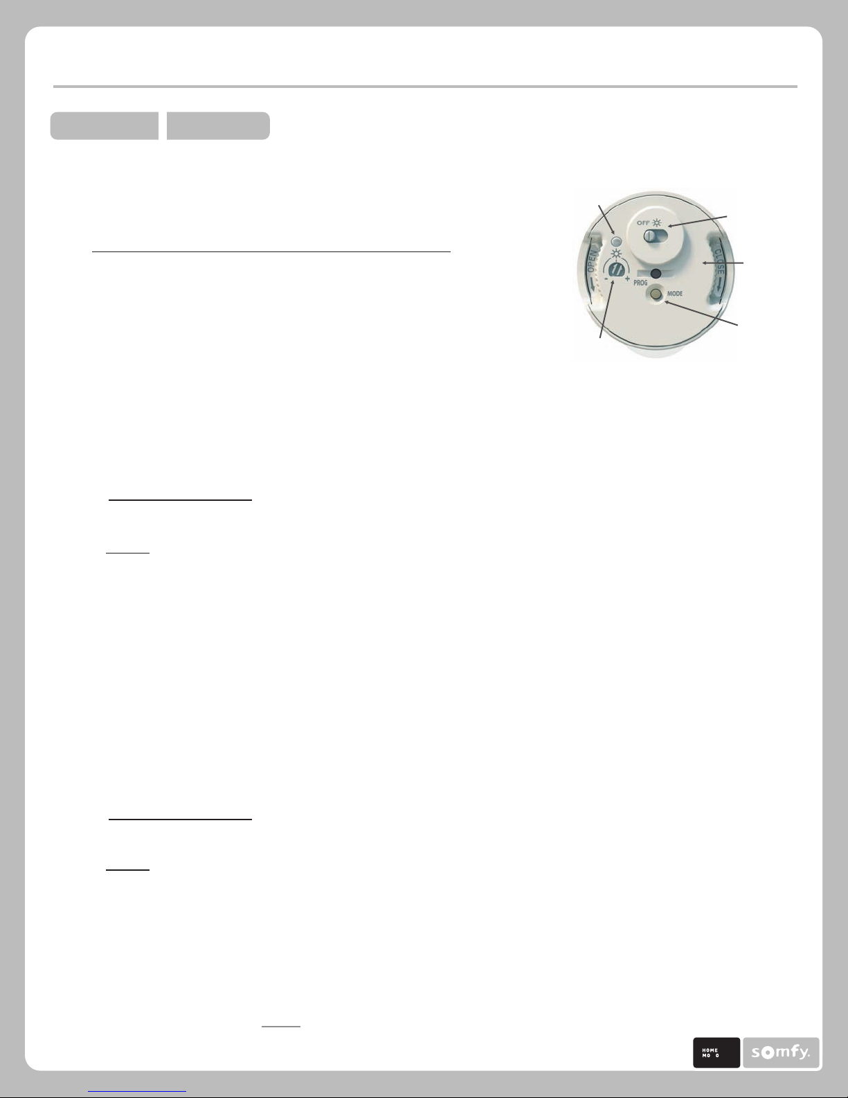
4. Using a small screw driver (or similar device) rotate the Sun Sensitivity Selector to the fully CLOCKWISE (+) position.
LED will remain illuminated (red color) (See Figure 4)
5. Slowly rotate the Sun Sensitivity Selector COUNTER CLOCKWISE (-) until the LED indicator illuminates to a green
color. A green colored LED indicates the present light value (threshold) At this value (threshold) the Sunis sensor
will provide the necessary DOWN COMMAND to the motor or RTS receiver.
FIGURE 4
On/Off
Selector Switch
Control
Setting Panel
Mode Button
*Note: Rotating the Sun Sensitivity Selector to a FULL COUNTER CLOCKWISE (-) position will simulate sun
if no sun is present. It is not recommended to leave the selector (Threshold setting) in this position.
TI N
BY
P.2 Rev2.
Page 3
Sunis WireFree RTS Light Sensor Programming/Operating/Installation Instructions
™
STEP FOUR OPERATION
The Sunis WireFree RTS Light Sensor cans be operated in either
Demonstration Mode (temporary) or Standard (default) mode.
FIGURE 5
DEMONSTRATION MODE
LED
Indicator
Demonstration mode reduces the standard operating time delays,
permitting almost instantaneous operating/output response from the
Sunis light sensor. This mode facilitates initial light sensitivity (threshold)
settings and quickly demonstrates the operation of the motorized end product.
1. Press and hold MODE BUTTON until LED indicator blinks (color red)
LED will continue to blink for approx. 30 seconds then extinguish.
(See Figure 5)
*Sun
Sensitivity
Selector
2. If necessary, adjust sun sensitivity (threshold) setting (refer to STEP 3. [4 & 5] )
LED will blink during this mode. Should LED indicator extinguish prior to final setting, simply press the
mode button momentarily to reactivate blinking LED indicator.
3. Sunis RTS light sensor will send a "DOWN" command to the RTS receiver or motor after 5 seconds of sensing light
within the set threshold.
On/Off
Selector Switch
Control
Setting Panel
Mode Button
4. Sunis RTS light sensor will send a "UP" command to the RTS receiver or motor IMMEDIATELY after sensing light that
HAS NOT reached (or below) the set threshold.
Note:
1. Sunis light sensor will automatically default to standard operating mode after 3 minutes.
2. *Rotating the Sun Sensitivity Selector to a FULL COUNTER CLOCKWISE (-) position will simulate sun
if no sun is present. It is not recommended to leave the selector (Threshold setting) in this position.
STANDARD OPERATING MODE
Standard operating mode (default) employs output response time delays.
1. Refer to STEP 3. [1-5] (Setting the Light (Sun) Sensitivity Threshold)
2. Sunis RTS light sensor will send a "DOWN" command to the RTS receiver or motor after 5 Minutes of sensing light
within the set threshold.
3. Sunis RTS light sensor will send a "UP" command to the RTS receiver or motor after 30 Minutes of sensing light that
HAS NOT reached (or below) the set threshold.
Note: LED indicator light will remain illuminated for approx. 15 seconds. To confirm
present light level, momentarily press the mode button to illuminate the LED indicator light.
GREEN LED: INDICATES SUN (Light) WITHIN THRESHOLD SETTING
RED LED: INDICATES SUN (Light) BELOW THRESHOLD SETTING
Note: The Sunis WireFree RTS light sensor is capable of providing control in accordance to light level conditions only.
Once a command is sent, the Sunis will not send another command until there is a change in light condition.
TI N
BY
P.3 Rev2.
Page 4
Sunis WireFree RTS Light Sensor Programming/Operating/Installation Instructions
™
6. REPLACING THE BATTERY
The Sunis WireFree RTS Light Sensor uses a lithium battery (Type: CR2430)
LED INDICATOR LIGHT will illuminate Orange (color) when battery
needs replacing.
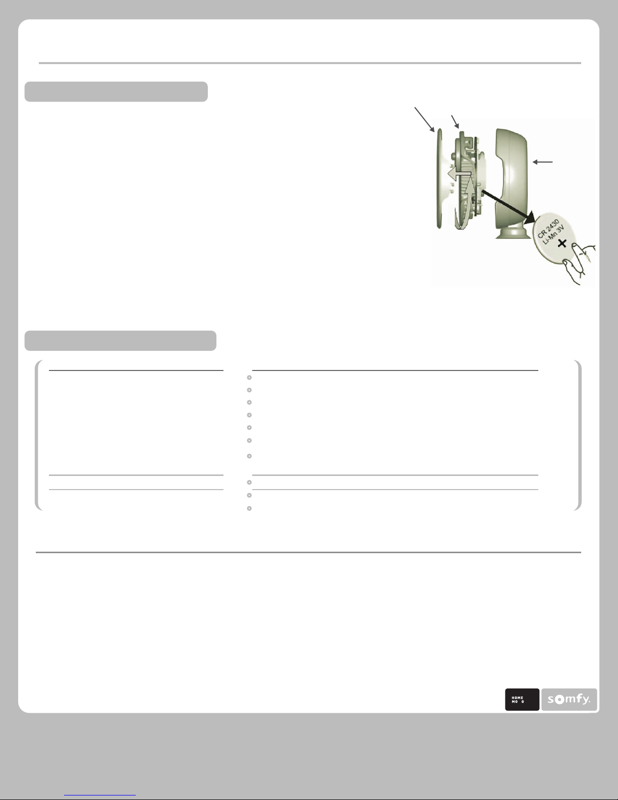
1. Carefully remove rear cover of Sunis Light sensor exposing the control
setting panel. (See Figure 5)
2. Firmly grip the molded indentations and rotate control setting panel
to open (counter clock wise) position.
3. Carefully separate from sensor case to expose battery holder.
4. Replace battery with correct rated/type battery. Be certain of battery polarity
(+) and (-) when installing new battery.
Note: Do not use any tools when replacing the battery as there is a risk of
damaging the sensor circuitry.
7. TROUBLESHOOTING GUIDE
PROBLEM
Window covering does not react to
Sunis Sensor
Window covering moves too frequently
Window covering reacts incorrectly
POSSIBLY CAUSE
The Sensor Selector is in the “Off” position.
The Sensor is not programmed to motor or RTS receiver.
The Light sensitivity (Threshold) values are incorrectly set.
The Battery is low/weak and needs replacing.
The Sensor cover is dirty or obstructed.
The Sensor is incorrectly positioned/mounted.
Window covering may have received a subsequent command from
another RTS control (i.e., Telis transmitter or Chronis timer)
The Sensor is in “Demo” mode
A bright light source is affecting the sensor.
Motorized window covering (Directional output) is programmed incorrectly
Rear
Cover
Control
Setting Panel
Sensor Case
FIGURE 5
FCC INFORMATION
This device complies with Part 15 of the FCC Results. Operation is subject to the following two conditions:
1. The device may not cause harmful interference, and 2. This device must accept any interference received, including that which may cause undesired operation.
NOTE: This equipment has been tested and found to comply with the limits for CLASS B digital device, pursuant to Part 15 of FCC Rules. These limits are designed
to provide reasonable protection against harmful interference when the equipment is operated in a commercial environment. This equipment generates, uses
and can radiate radio frequency energy and, if not installed and used in accordance with the instructions, may cause harmful interference to radio communications.
However, there is no guarantee that interference will not occur in a particular installation. If this equipment does cause harmful interference to radio television
reception, which can be determined by turning the equipment off and on, the user is encouraged to try to correct the interference by one or more of the following
measures:
1. Reorient or relocate the receiving antenna 2. Increase the separation between the equipment and receiver3. Connect the equipment into an outlet on a
circuit different from that to which receivers connected 4. Consult the dealer or experienced radio TV technician for help.
WARNING: Changes or modifications not expressly approved by the manufacturer could void the user’s authority to operate
the equipment.
Somfy Systems, Inc.
North America Headquarters
47 Commerce Drive
Cranbury Nj 08512
(P) 800 222 SOMFY
(P) 609 395 1300
(F) 609 395 1776
Florida
6100 Broken Sound Pkwy
Northwest Suite 14
Boca Raton, Fl 33487
(P) 877 227 6639
(P) 561 995 8376
(F) 561 995 7502
California
15291 Barranca Pkwy
Irvine, Ca 92618
(P) 877 727 6639
(F) 949 727 3775
Somfy Ulc
Somfy Canada
6315 Shawson Drive Unit 1
Mississauga, Ontario L5t1j2
(P) 800 667 6639
(P) 905 564 6446
(F) 905 564 2679
TI N
BY
SOMFY SYSTEMS, INC. reserve the right
change, update or improve this
document without prior notice.
© Somfy Systems, Inc. 2/2009
P.4 Rev2.
 Loading...