

Page 1
Sonesse Ultra 50 RTS
Sonesse Ultra 50 RTS RH
Instructions
EN
Notice
FR
Ref. 5120786A
Page 2

Page 3

EN
ORIGINAL GUIDE
These instructions applies to all Sonesse Ultra 50 RTS and Sonesse Ultra 50 RTS RH drive
irrespective of torque and speed variations.
CONTENTS
1. Prerequisite information 12
1.1 Fields of application 12
1.2 liability 13
2. Installation 13
2.1. Installation 13
2.2. Wiring 14
2.3. Commissioning 15
2.4. Tips and recommendations for
installation 17
The Sonesse Ultra 50 RTS drive has been developed to meet indoor awning drive requirements.
Its quiet operation ensures user comfort and well-being.
For more information, and to optimise the acoustic performance of your indoor awning, please
contact a Somfy adviser.
3. Use and maintenance 18
3.1. Up and Down buttons 18
3.2. STOP function 18
3.3. Favourite position (my) 18
3.4. Additional settings 19
3.5. Tips and recommendations for use 19
4. Technical data 20
1. PREREQUISITE INFORMATION
1.1 FIELDS OF APPLICATION
The Sonesse 50 drive is designed to drive all types of indoor awning
(Roller blinds and projection screens), excluding pantographs.
The Sonesse 50 drive is designed to drive multi-banding roller blinds.
The Sonesse 50 drive is designed to drive several roller blinds simultaneously, where these are
interconnected by a drive bracket.
The Sonesse 50 drive is not designed to be used with a compensating spring.
Any use outside the elds of application is prohibited, in particular:
The Sonesse 50 drive is not designed for outdoor awnings (e.g. outdoor vertical blinds, roller
shutters, etc.)
Copyright © 2014 Somfy SAS. All rights reserved.
Images not contractually binding
3
Page 4
EN
1.2 LIABILITY
Before installing and using the drive, please read operating and installation guide carefully. In addition to following the instructions given in this guide, the instructions detailed in the
attached Safety instructions document must also be observed.
The drive must be installed by a drive and home automation professional, according
to instructions from Somfy and the regulations applicable in the country in which it is
commissioned.
It is prohibited to use the drive outside the elds of application described above. Such use,
and any failure to comply with the instructions given in this guide and in the attached Safety
instructions document, absolves Somfy of any liability and invalidates the warranty.
The installer must inform its customers of the operating and maintenance conditions for the
drive and must provide them with the instructions for use and maintenance, and the attached
Safety instructions document, after installing the drive. Any After-Sales Service operation on
the drive must be performed by a drive and home automation professional.
If in doubt when installing the drive, or to obtain additional information, contact a Somfy adviser
or go to the website www.somfy.com.
Safety warning!
Caution!
Information
Λ Up V Down
2. INSTALLATION
Instructions which must be followed by the drive and home automation professional
installing the drive.
Never drop, knock, drill or submerge the drive.
Install a separate control point for each drive.
To optimize silence, the mechanical plays between motor, accessories, tube and end of
tube must be decreased to the maximum.
2.1. INSTALLATION
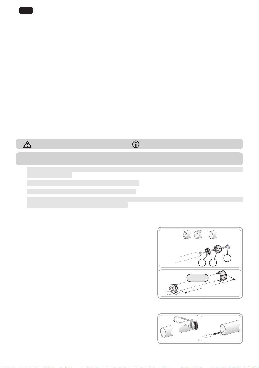
2.1.1. Preparing the drive
Check that the inner diameter of the tube greater than
47mm.
1) Fit the accessories required to integrate the drive in the
roller tube:
• Fit the crown a, the drive wheel b and the stop wheel c
on the drive.
The stop wheel must be screwed with a torque ranging
between 1.5 and 1.8 Nm.
2) Measure the length (L1) between the inner edge of the
drive head and the rim of the drive wheel.
2.1.2. Tube preparation
1) Cut the roller tube to the required length, depending on
the motorised product.
2) Deburr the roller tube and remove the swarf.
1)
2)
1) 2)
L1 = …
Ø > 47 mm
ba
L1
c
4
Images not contractually binding
Copyright © 2014 Somfy SAS. All rights reserved.
Page 5

2.1.3. Drive/tube assembly
N
L
1) Slide the drive into the roller tube.
1)
For roller tubes which are smooth inside, position the notch
previously cut on the boss on the crown.
2) The drive wheel must be locked in place to prevent it
moving along the roller tube:
2)
• This can be done either by xing the roller tube to the
drive wheel using 4 x Ø 5 mm self-tapping screws,
or by using 4 x Ø 4.8 mm steel pop rivets placed 5
mm to 15 mm from the outer rim of the drive wheel,
regardless of the roller tube.
The screws or pop rivets must only be attached to the
drive wheel and not to the drive.
3)
3) Slide the end cap into the roller tube.
2.1.4. Installing the drive/tube assembly
The motorised product must not be compressed between the brackets
1) Install and x the drive/tube assembly onto the end
bracket f and onto the drive bracket g:
Ensure that the drive/tube assembly is secured onto
the end bracket. This operation prevents the drive/
tube assembly from coming out of the end bracket
mounting when the roller blind reaches the lower end
limit position.
1)
g
2)
h
2) Depending on the type of bracket, t the stop ring h in
place.
15 mm
L1
EN
5 mm
20 mm
f
2.2. WIRING
Cables which pass through a metal wall must be protected and isolated using a sheath
or sleeve.
Attach cables to prevent any contact with moving parts.
The cable on the Sonesse Ultra 50 can be removed. If it is damaged, replace it with an
identical cable.
Leave the drive power supply cable accessible: it must be possible to replace it easily.
- Switch off the power supply.
- Connect the drive according to the information in the table below:
Neutral
(N)
120V-60Hz
Copyright © 2014 Somfy SAS. All rights reserved.
White Black Green
Live
(L)
Earth
( )
Images not contractually binding
5
Page 6

EN
a
b
=
=
a
b
=
=
2.3. COMMISSIONING
2.3.1. Pre-programming the RTS control point
1) Switch on the power supply.
2) Press the
the same time: The motorised product moves up and
down (fast raising and lowering), and the RTS control
point is pre-programmed in the motor.
The motorisation is in programming mode for ≈ 10 min.
2.3.2. Checking the direction of rotation
1) Press the Λ button on the RTS control point:
a) If the motorised product rises (a), the direction
of rotation is correct: Move onto the section
entitled “Setting the end limits”.
b) If the motorised product lowers (b), the direction
of rotation is incorrect: Move onto the next step.
2) Press the my button on the RTS control point
until the motorised product moves up and down: The
direction of rotation has been modied.
3) Press the
check the direction of rotation.
2.3.3. Setting the end limits
The end limits can be set in any order.
1) Raise the motorised product to the desired position
by pressing the
2) Press the my and
the motorised product moves.
The upper end limit is memorised.
3) Press the my button when the motorised product
reaches the desired lowered position. If necessary,
adjust the position of the motorised product using the
Λ/V buttons on the RTS control point at
Λ button on the RTS control point to
Λ button.
V buttons at the same time until
1)
2) 3)
1) 2)
3) 4)
Λ and V buttons.
4) Press the my and
the motorised product moves.
The lower end limit is memorised. The motorised product rises and stops in the raised position.
2.3.4. Validation of the setting
To conrm the end limits, press the my button until
the motorised product moves up and down.
The end limits are programmed.
Λ buttons at the same time until
21
6
Images not contractually binding
Copyright © 2014 Somfy SAS. All rights reserved.
Page 7

2.3.5. Recording the RTS control point
PROG.
The motorisation is in programming mode:
-- Quickly press the PROG button on the RTS control
point to be programmed:
→The motorised product moves up and down: this
RTS control point is programmed in the motorisation.
If the motorisation is no longer in programming mode, repeat Step 2.3.1 then perform
Step 2.3.4.
2.3.6. Adding/Deleting Somfy control points and sensors
Refer to the corresponding guide.
2.4. TIPS AND RECOMMENDATIONS FOR INSTALLATION
2.4.1. Questions about the Sonesse Ultra 50 RTS?
Observations Possible causes Solutions
The wiring is incorrect. Check the wiring and modify it if necessary.
The motorised product
does not operate.
The Drive is in thermal protection. Wait until the motor cools down.
EN
The control point battery is weak.
The control point is not
compatible.
The control point used has not been
programmed into the motor.
The motorised
product is noisy:
The motorised product
stop to soon or to late.
Copyright © 2014 Somfy SAS. All rights reserved.
The drive wheel and the crown are not
suitable for the tube.
The motorised product is compressed
between the brackets
The tube contains swarf and screws. Clean the roller tube.
The end-limits of the motorised product
drift.
Check whether the battery is weak and replace
it if necessary.
Check for compatibility and replace the control
point if necessary.
Use a programmed control point or program this
control point.
Replace the drive wheel and the crown
Increase the play between the brackets
Readjust the end-limits
Images not contractually binding
7
Page 8

EN
A
PROG.
B
2.4.2. Re-setting the end limits
Readjusting the upper end limit
1) Press the
product to the end limit to be readjusted.
2) Press the
until the motorised product moves up and down.
3) Press the
product to the new desired position.
4) To conrm the new end limit, press the my
button until the motorised product moves up and
down.
Readjusting the lower end limit
1) Press the
product to the end limit to be readjusted.
2) Press the
until the motorised product moves up and down.
3) Press the
product to the new desired position.
4) To conrm the new end limit, press the my
button until the motorised product moves up and
down.
Λ button to bring the motorised
Λ and V buttons at the same time
Λ or V button to move the motorised
V button to bring the motorised
Λ and V buttons at the same time
Λ or V button to move the motorised
1) 2)
3) 4)
1) 2)
3) 4)
2.4.3. Replacing a lost or broken Somfy control point
Only switch off the power to the application to
be reset.
This reset deletes all the local control points,
however the sensors, end limit settings and
favourite position are retained.
1) Position the motorised product at the mid-height
position.
2) Cut the power supply for 2 seconds.
3) Switch the power supply back on for 5 to 15
seconds.
4) Cut the power supply for 2 seconds.
5) Switch the power supply back on: the motorised
product moves for a few seconds. (If the application is in the upper or lower limit position, it will
make a brief up and down movement).
6) Press the PROG button on the new control point
until the motorised product moves up and down:
the new control point is programmed and all the
other control points are deleted.
8
Images not contractually binding
1) 2)
3) 4)
5)
6)
Copyright © 2014 Somfy SAS. All rights reserved.
Page 9

2.4.3. Restoring the original conguration
PROG.
A
A
B
MY
X 2
C
Only switch off the power to the application to
be reset.
This reset deletes all control points, all the sensors
and all the end limit settings, and resets the motor’s
favourite position (my).
1) Position the motorised product at the mid-height
position.
2) Cut the power supply for 2 seconds.
3) Switch the power supply back on for 5 to 15
seconds.
4) Cut the power supply for 2 seconds.
5) Switch the power supply back on: the motorised
product moves for a few seconds. (If the application
is at the upper or lower end limit, it will make a brief
up and down movement).
6) Press the PROG button on the Somfy local
control point for ≈ 7 seconds, until the motorised
product moves up and down twice:
→ The motorisation is reset to the original
conguration.
- Repeat the commissioning procedure (see
Commissioning) section.
3. USE AND MAINTENANCE
This drive is maintenance-free
EN
1) 2)
3) 4)
5)
6)
For the safety of goods and people, Somfy motors are equipped with thermal protection
that will trigger the motor stops in the event of overheating.
Repeated achieving this protection can degrade engine performance.
If the motor goes to thermal protection, please check your installation and check that the
motor is rated for the intended use.
A normal installation is not expected to trig this protection.
To avoid the drift of the end limits, do not cut the power supply more than 1 week.
3.1. UP AND DOWN BUTTONS
Pressing the Λ or V button fully raises or lowers the
motorised product.
3.2. STOP FUNCTION
The motorised product is moving.
- Briey press my: the motorised product stops
automatically.
Copyright © 2014 Somfy SAS. All rights reserved.
1)
2)
Images not contractually binding
9
Page 10

EN
3.3. FAVOURITE POSITION (my)
Besides the upper and lower positions, an intermediate position known as the “favourite
position (my)” is programmed as standard in the Sonesse 50.
To use the favourite position (my):
- Briey press my: the motorised product starts to
3)
move, and stops in the favourite position (my).
To modify or delete the favourite (my) position, see
the section entitled “Additional settings”.
3.4. ADDITIONAL SETTINGS
3.4.1. Modifying the favourite position (my)
1) Place the motorised product in the desired favourite
position (my).
2) Press my for ≈ 5 seconds until the motorised
product moves up and down: the desired favourite
position (my) has been programmed.
1)
2)
3.4.2. Deleting the favourite position (my)
1) Press my: the motorised product starts to move,
1)
2)
and stops in the favourite position (my).
2) Press my again until the motorised product moves:
the favourite position (my) is deleted.
3.5. TIPS AND RECOMMENDATIONS FOR USE
3.5.1. Questions about the Sonesse Ultra 50 RTS?
Observations Possible causes Solutions
The motorised product
does not operate.
The control point battery is weak.
The motorisation is in thermal protection
mode.
If the motorised product still does not work, contact a motorisation and home automation
professional.
3.6.2. Replacing a lost or broken Somfy control point
To replace a lost or broken control point, contact a motorisation and home automation
professional.
Check whether the battery is weak and replace
it if necessary.
Wait for the motor to cool down.
10
Images not contractually binding
Copyright © 2014 Somfy SAS. All rights reserved.
Page 11

4. TECHNICAL DATA
Power supply 120V~ 60 Hz
Radio frequency 433.42 MHz
Operating temperature 0°C to + 60°C
Index protection rating IP 31
Safety level Class I
Maximum number of control points 12
Maximum number of sensors 3
EN
Somfy hereby declares that t he drive covered by these instruc tions whe n marked for i nput volta ge 230V 50 Hz when use d as
inten ded acc ording to these inst ruct ions, is in co mpliance with th e essent ial requiremen ts of the Mach iner y Direct ive 200 6/42/ EC
and the R&TTE Dir ective 1999 /5/EC.
nam e and addr ess of th e pers on(s) aut hor ised to compi le the te chni cal l e and emp ower ed to draw up the dec lara tion inclu ding pl ace an d date of
issue can be found at the Internet add ress www.somfy.com /ce.
An EC dec lar at ion of con form it y det ai lin g st and ar ds an d spe ci c ation s use d and sta tin g all par ti cul ars fo r ide ntic atio n of th e dri ve,
Copyright © 2014 Somfy SAS. All rights reserved.
Images not contractually binding
11
Page 12

Page 13

Somfy SAS
50 avenue du Nouveau Monde
F-74300 CLUSES
www.somfy.com
Somfy SAS, capital 20.000.000 Euros, RCS Annecy 303.970.230 -09/2014
 Loading...